This document describes the enhancements that are delivered in Oracle Communications Unified Inventory Management (UIM) 7.4.2 patches.
See the following for information on each patch:
Enhancements in UIM 7.4.2.1 (Patch 33429660)
The following sections describe the enhancements delivered in this patch:
- New API to Validate the Availability of IP Subnets before Joining
- Exporting Connected Trails in Connectivity Search Results Page
- Viewing Multiple Paths in a Connectivity Design Page
- Displaying Physical Device Details in Physical Port Summary Page
- Enabling ‘IN’ Operator to Search the List of Operators Based on String Values
- Viewing Associated Entities or Inventory Groups from Place Summary Page
- Support to Include configItem Information in UIM REST GET Service API Response to
- Organizing Characteristics in Different Collapsible Sections in UIM UI
New API to Validate the Availability of IP Subnets before Joining
You can use IPNetworkManager.validateJoinIPv4Subnets API to validate the availability of IP subnets before joining. See “About Joining IP Subnets” section in UIM Concepts Guide for more information on joining subnets and the corresponding validations.
The API is as follows:
validateJoinIPv4Subnets(IPSubnet subnet, int prefixLength)Where, IPSubnet is the IP subnet to be validated and
prefixLenghth is the length of the subnet.
After validating, the API returns true if the subnet is valid for joining, else it returns false.
Exporting Connected Trails in Connectivity Search Results Page
You can now search for a connectivity using its characteristics and you can view these characteristics in the search results. You can export the search results in to a spreadsheet file.
The following search columns are added to the connectivity Search Results section:
- A End DI Termination Point
- Z End DI Termination Point
- A End Logical Device
- Z End Logical Device
- A End Port Name
- Z End Port Name
- Characteristics (if any)
To export the connected trails in connectivity search:
- Navigate to Connectivity.
- Select a specification in the Connectivity search criteria.
- (Optional) To change the default search criteria:
- Click Add Fields.
The Add Fields dialog box appears.
- Use the directional arrow buttons to move the characteristics between the Available Fields column to the Selected Fields column.
- Click OK.
The selected fields appear in the Search section.
- Click Add Fields.
- Enter search criteria in the desired fields.
- Click Search.
A table of search results appears in the Search Results section.
- Click Export.
The search results are exported to a spreadsheet.
Viewing Multiple Paths in a Connectivity Design Page
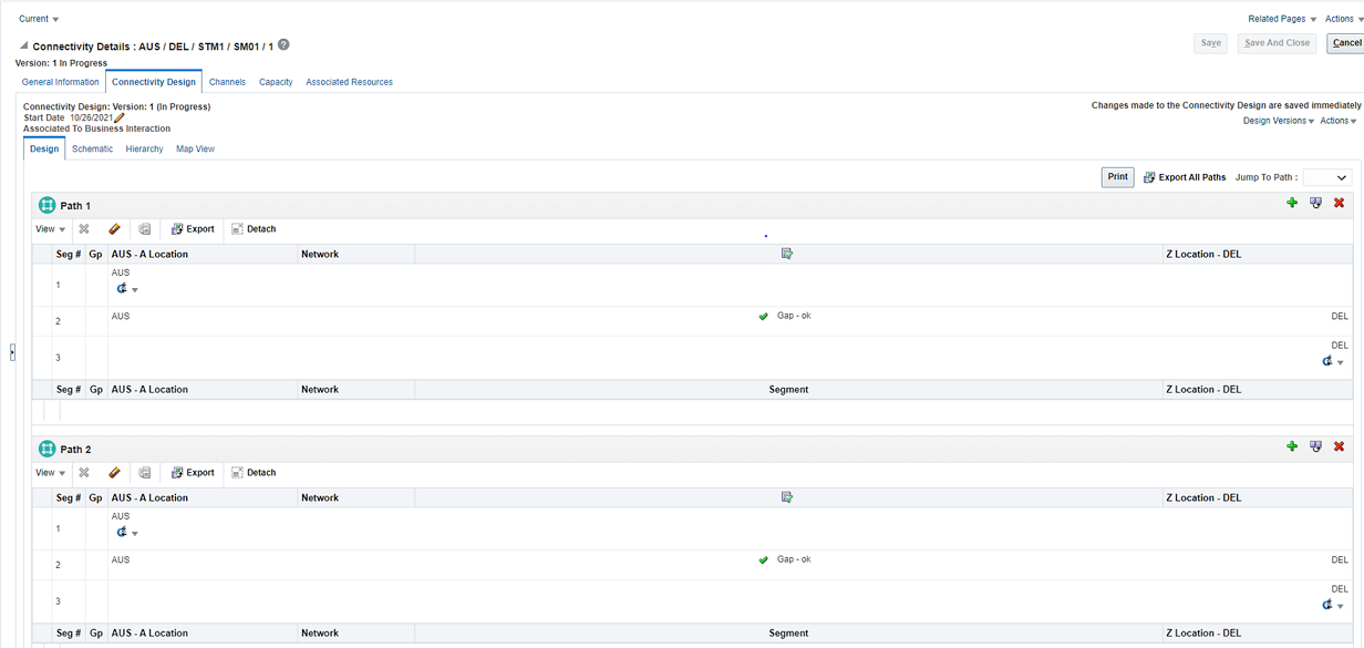
When there are multiple paths in a connectivity, you can view all the paths in a single connectivity design for easy comparison. You can view the multiple paths in Design and Schematic subtabs of the Connectivity Design tab.
Design Subtab
Instead of switching between the paths, you can view all the paths in a table.
Figure 1-1 illustrates multiple paths in a table.
Figure 1-1 Connectivity Design Subtab with Multiple Paths
The following options are available:
- To add, duplicate, and remove a path, use the options available on the top-right corner of the corresponding path table.
- To print all paths, use Print on the top-right corner above all path tables.
- To export all paths into a spreadsheet, use Export All Paths on the top-right corner above all path tables.
- To go to any specific path, use Jump To Path on the top-right corner above all path tables and select the required path you want to see.
Schematic Subtab
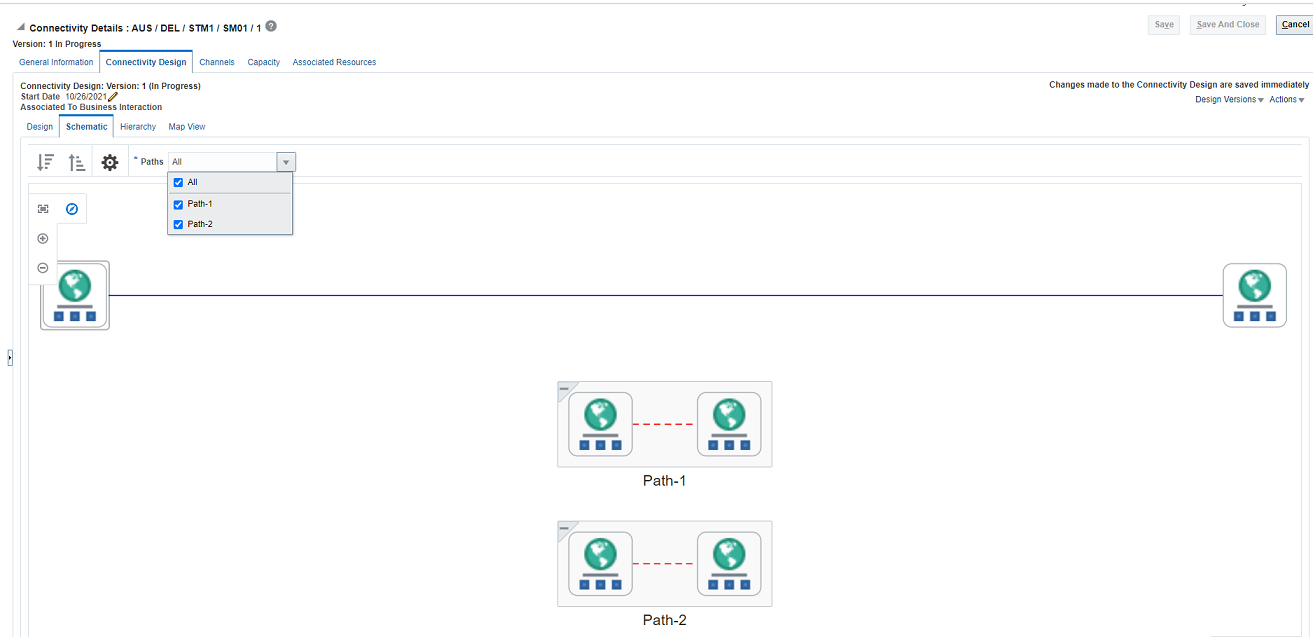
You can now view multiple paths in a schematic view. You can select all paths, any specific path, or multiple paths using the corresponding check boxes available under Paths dropdown list.
Figure 1-2 illustrates the selection of multiple paths in schematic view.
Figure 1-2 Connectivity Schematic Subtab with Multiple Paths
Displaying Physical Device Details in Physical Port Summary Page
You can view the physical device that is mapped to a physical port from the corresponding Physical Port Summary page. You can view these details under the Physical Device section of the Physical Port Summary page.
Table lists the fields in Physical Device section.
Table 1-1 Physical Device Fields
| Field | Description |
|---|---|
|
Physical Device |
Displays a clickable link to the Physical Device Summary page. |
| Physical Address | Displays the physical address of the physical device. |
| Network Location | Displays a clickable link to the property location of the physical device. |
| Physical Location | Displays the physical location of the physical device. |
Enabling ‘IN’ Operator to Search the List of Operators Based on String Values
In UIM entity search pages, you can use IN operator from the Operators dropdown list to search based on a list of string values. After you select IN from Operators list, a text field appears. You can enter up to 10 string values that are separated by commas.
Note:
The maximum length of this field is 100 characters.You use uim.ui.search.SearchINOperatorEnable parameter and set its value to true in system-config.properties file to set this field. This field is not available by default because the default parameter value is false. To enable this field you need to set the parameter value to true.
The maximum length of this field is set to 100 by using uim.ui.search.SearchTextMaxlen parameter in config.properties file.
Viewing Associated Entities or Inventory Groups from Place Summary Page
You can view the place associated to an inventory group under the Associated Resources tab of the Place Summary page. You can also associate or disassociate the inventory group from this page.
Support to Include configItem Information in UIM REST GET Service API Response to
Services can have multiple configItems and multiple resources are assigned or referenced to each of these configItems. You cannot find the mapping between the resource and configItems without the corresponding configItem information in service GET API response.
The GET Service API is improved to provide configItem Id, name, and display name of each resource under the service.
Organizing Characteristics in Different Collapsible Sections in UIM UI
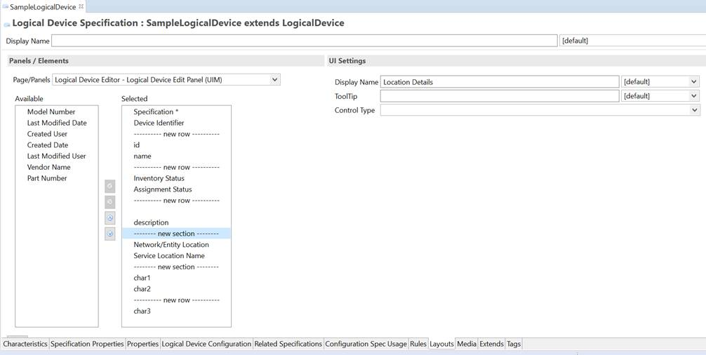
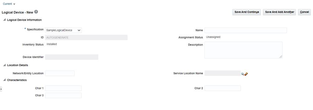
Enhanced UIM UI to group characteristics associated with an entity specification into separate sections in Edit, Range Edit, and Summary pages. You can group the characteristics while updating the layout of entity specifications in Design Studio.
To add a section in the Layouts tab from Design Studio:
- Open the entity specification.
- Open the Layouts tab and select the page section that needs to be updated.
- Right-click on the required characteristic or attribute in the selected column.
- Select Insert New Section.
- Click on the section that is added and enter the details in Display Name and
ToolTip.
Note:
Display Name is a mandatory field and ToolTip is an option field. - Place the required attributes or characteristics under the selected section using up arrow and down arrow buttons.
- Save the specification.
Figure 1-3 illustrates an example of adding new sections in the Logical Device Edit panel.
Figure 1-3 Adding New Sections in Logical Device Edit Panel in Design Studio
Figure 1-4 illustrates the Logical Device – New page that displays the grouped characteristics.
Figure 1-4 Logical Device – New page Displaying Grouped Characteristics
Documentation Accessibility
For information about Oracle's commitment to accessibility, visit the Oracle Accessibility Program website at http://www.oracle.com/pls/topic/lookup?ctx=acc&id=docacc.
Access to Oracle Support
Oracle customers that have purchased support have access to electronic support through My Oracle Support. For information, visit http://www.oracle.com/pls/topic/lookup?ctx=acc&id=info or visit http://www.oracle.com/pls/topic/lookup?ctx=acc&id=trs if you are hearing impaired.
Oracle Communications Unified Inventory Management What's New, Release 7.4.2
F49341-01
October 2021
Copyright © 2021, Oracle and/or its affiliates.


