14 Enabling Geographic Redundancy and Disaster Recovery
This chapter describes a generic architecture for UIM across multiple geographically redundant sites in a primary-standby (active-passive) deployment. This chapter provides the following information:
- Architecture for Geographically Redundancy (GR) in UIM
- Installation, configuration, and operational best practices
- Switchover and failover test procedures and test results
About Geographic Redundancy and Disaster Recovery in UIM
The UIM application architecture supports high availability across distributed application and database clusters in a typical single site deployment. UIM operations run continuously regardless of the failure of a single application or database node in a production environment. However, in some cases, continuity of operations with minimal loss of service is required, in the event of a complete failure (due to a natural disaster) in the primary UIM or OSS application stack.
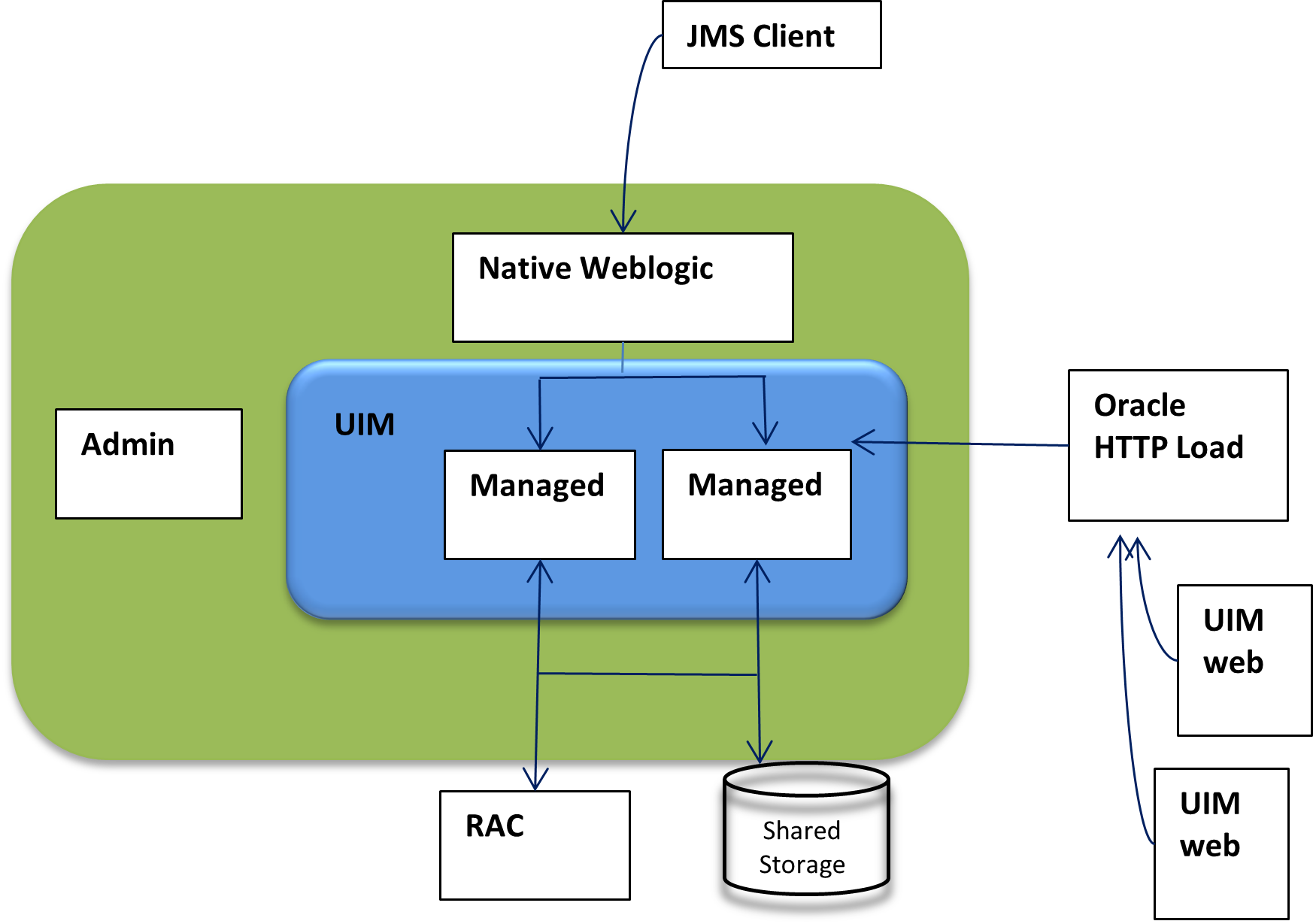
The following figure shows a highly available single-site architecture is comprised of: UIM, deployed to a clustered WebLogic domain with two or more managed servers on multiple hosts, and an active-active RAC database. When a single managed server or database instance becomes unavailable, the surviving nodes can automatically take up the excess load. For more information on system requirements for attaining UIM high availability, see Unified Inventory Management System Requirements.
Additional resiliency is achieved when UIM is deployed to geographically redundant sites in a symmetric primary-standby configuration, where the standby site is a duplicate of the primary site. When the primary site becomes unavailable and cannot be recovered within a reasonable amount of time or with a reasonable amount of effort, UIM services can fail over to the standby site, effectively making the standby site the new primary site.
This chapter describes a generic architecture for UIM across multiple geographically redundant sites in a primary-standby (active-passive) deployment. The architecture described provides guidelines for projects with geographically redundant site availability requirements.
This chapter provides information about the following:
- Architecture for Geographically Redundancy(GR) for UIM
- Installation, configuration, and operational best practices
- Switchover and failover test procedures and test results
About Switchover and Failover
The purpose of a geographically redundant deployment is to provide resiliency in the event of a complete loss of service in the primary site, due to a natural disaster or other unrecoverable failure in the primary UIM site. The resiliency is achieved by creating one or more passive standby sites that can take the load when the primary site becomes unavailable.
The role reversal from the standby site to the primary site can be accomplished in any of the following ways:
- Switchover, in which the operator performs a controlled shutdown of the primary site before activating the standby site. This is primarily intended for planned service interruptions in the primary UIM site. Following a switchover, the former primary site becomes the standby site. The site roles of primary site and standby site can be restored by performing a second switchover operation, which is switchback.
- Failover, in which the primary site becomes unavailable due to unanticipated reasons and cannot be recovered. The operator then transitions the standby site to the primary role. The primary site that is down cannot act as a standby site and will require reconstruction of the database as a standby database before restoring the site roles.
Geographically Redundant Traditional UIM Deployment
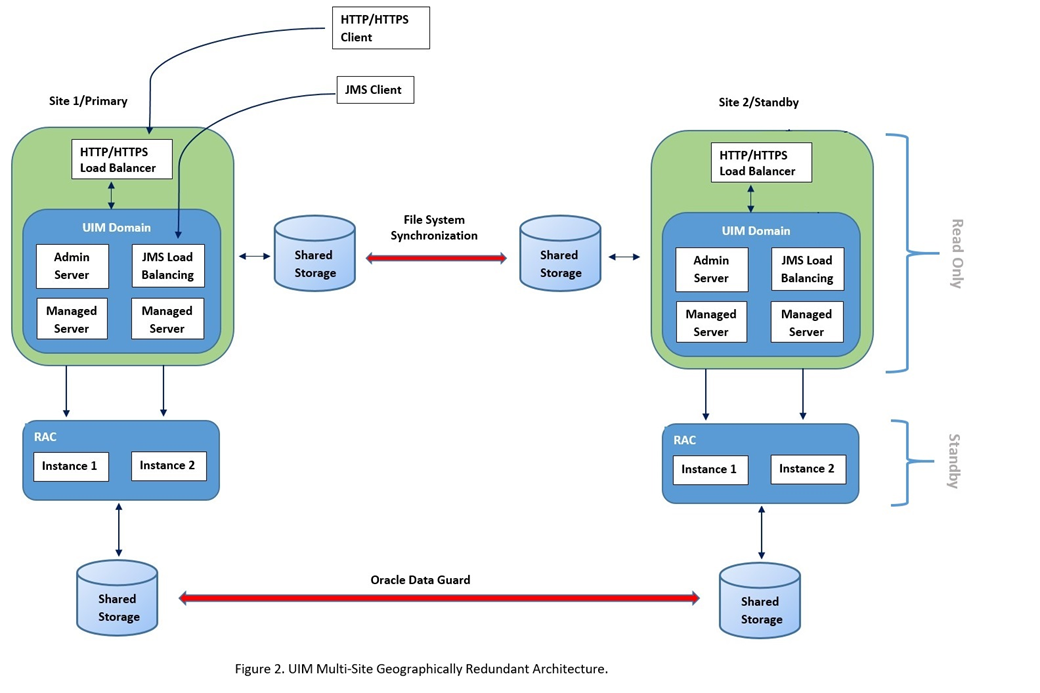
A geographically redundant UIM deployment comprises two or more geographically distant sites: a primary site, which has the production environment, and one or more offline standby sites where each site includes the UIM deployment and its associated RAC database as shown in the following figure.
About the Primary Site
The primary site is identical in nature to a typical single-site deployment of UIM (see Figure 1). The application layer consists of a clustered WebLogic domain with two or more managed servers, an Admin server, and an HTTP/HTTPS load balancer. Additionally, using a Node Manager on each machine in the domain is recommended to manage the admin server and managed server processes.
The UIM workload is distributed across the managed servers in the WebLogic cluster. If a cluster node goes down, the workload is redistributed across the surviving cluster nodes. A Store-and-Forward (SAF) agent can provide additional resiliency for JMS messages by buffering incoming requests, if the destination JMS targets become unavailable.
The database layer consists of a RAC database, typically in an active-active configuration, where each managed server is affiliated with a given database instance. In the event of a failure in a single database instance, the surviving instance will pick up the load. The database layer stores all transactional data including:
- JMS messages backed by a JDBC persistent store
- SAF messages
- UIM data and Metadata
- LDAP Policy data
About the Standby Site
After either a switchover or failover operation, the targeted standby site assumes the role of a primary site for both the application stack and the database. Standby sites are synchronized periodically with the primary site to maintain service continuity in the event of a catastrophic failure at the primary site.
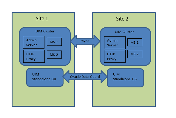
The above figure shows a two-site active/passive UIM configuration for geographic redundancy. In this deployment scenario, the primary and standby site(s) are installed in geographically different locations, typically in different data centers. Interconnection is established through WAN. This multi-site deployment has the following features:
- Multiple symmetric sites: In a multiple symmetric site, the primary site runs and actively processes service requests while the secondary site is passive; the secondary UIM WLS cluster is available but cannot process create and update requests while the database is in a standby role.
- The UIM WLS domain is replicated from the primary site to the secondary site using file system replication utilities such as.rsync.
- Oracle Data Guard is used to replicate the UIM RAC database from the primary site to the secondary site. All updates to the primary database (including database sequences) are automatically propagated to the secondary database in near-realtime.
The Oracle Data Guard standby database is not read-write accessible. As a result, the UIM application cluster cannot be run in the standby site.
Geographically Redundant UIM Cloud Native Deployment
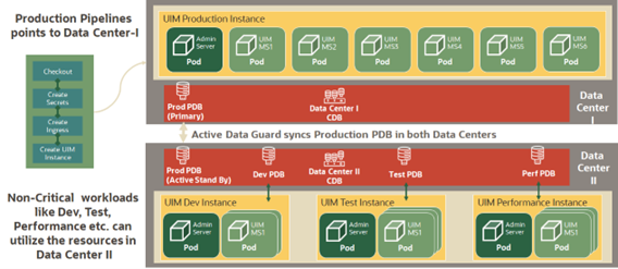
A geographically redundant UIM CN deployment comprises two or more geographically distant sites: a primary site, which has the production environment, and one or more offline standby sites where each site includes the UIM CN deployment and its associated RAC database as shown in the following figure.
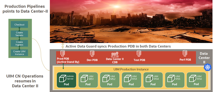
UIM in data center1 is the primary and active instance and UIM in data center 2 can be a cold/warm standby.
About the Primary Site
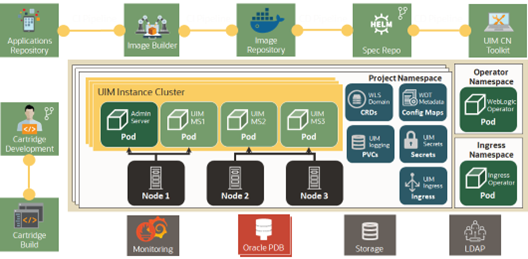
The primary site is identical to a typical single-site deployment of UIM. The application layer consists of a clustered WebLogic domain with two or more managed server pods, an Admin server pod, and an Ingress pod as load balancer. Additionally, there is a WebLogic Operator pod to support WebLogic server on Kubernetes environment. UIM CN pipelines are used for continuous deployment and these pipelines point to Data Center 1 in normal operations.
The UIM workload is distributed across the managed servers in the WebLogic cluster. If a pod goes down, the workload is redistributed across the surviving cluster pods. And if a Kubernetes worker node goes down, then workload is distributed across managed servers on surviving Kubernetes nodes. A Store-and-Forward (SAF) agent can provide additional resiliency for JMS messages by buffering incoming requests when the destination JMS targets become unavailable.
The database layer consists of a RAC database, in an active-active configuration, where each managed server is affiliated with a given database instance. In the event of a failure in a single database instance, the surviving instance will pick up the load. The database layer stores all transactional data including:
- JMS messages backed by a JDBC persistent store
- SAF messages
- UIM data and Metadata
- LDAP Policy data
About the Standby Site
After a switchover or a failover operation, the targeted standby site assumes the role of a primary site for both the application stack and the database. Standby sites are synchronized periodically with the primary site to maintain service continuity in the event of a catastrophic failure at the primary site. The above figure shows a two-site active/passive UIM configuration for geographic redundancy. In this deployment scenario, the primary and standby site(s) are installed in geographically different locations, typically in different data centers. Interconnection is established through WAN. This multi-site deployment provides:
- Multiple symmetric sites: In multiple symmetric sites, the primary site runs and actively processes service requests while the secondary site is passive. The secondary UIM WLS cluster is available but cannot process create and update requests while the database is in a standby role.
- Non-critical workloads such as development, testing, and performance can utilize the resources in Data Center 2.
- Oracle Data Guard is used to replicate the UIM RAC database from the primary site to the secondary site. All updates to the primary database (including database sequences) are automatically propagated to the secondary database in near-realtime.
The Oracle Data Guard standby database is not read-write accessible. As a result, the UIM application cluster cannot be run in the standby site.
When a disaster strikes on DataCenter1, the following operations are performed:
- Stop all non-critical workloads in Data Center 2
- Redirect the production pipeline to use Data Center 2
Prerequisites for Geographic Redundancy
This section provides the prerequisites for supporting geographic redundancy in UIM.
Synchronize File Systems
For UIM geographic redundancy, Oracle recommends using a common file system utility such as rsync for replicating and synchronizing the primary site file system with the standby site. The rsync utility has the following advantages:
- It is available on most Unix and Linux distributions, including Oracle Solaris and Oracle Enterprise Linux.
- Differences between source and target files are computed using an algorithm that ensures that only the changes to files are copied from the primary site to the standby site.
- It can use SSH as a secure channel.
- If network bandwidth is an issue, rsync can compress data during transfer.
The rsync utility does not support creation of nested target subdirectories. You cannot create a full target directory path unless the target directory is a subdirectory of the source directory. For example, if the source directory is specified as /share/apps/Oracle and the target is specified as /share/apps/Oracle/Middleware/user_projects/domains/UIM_domain, rsync does not create the directories under ../Oracle.
Other options for file system replication include:
- Using ZFS. ZFS is available for Oracle Solaris and available in open-source variants for Linux
- Oracle Solaris Cluster Geographic Edition
- File system utilities such as rcp, scp, ftp, or sftp are not well suited for incremental synchronization, but can be used for initial file system replication
Synchronize UIM Domain
Oracle Data Guard can manage database synchronization without any additional file system updates. The standby UIM domain, on the other hand, must be kept in synchronous with the primary site by using ZFS, Oracle Solaris Cluster Geographic Edition, or other file system utilities that can be used for initial file system replication. Files that must be kept in continuous synchronization include any files that are expected to be created or modified during the normal course of UIM operation. For example:
- The system-config.properties file and other property files
- Java code changes that include hotfixes or changed rulesets containing Java code
If the rsync utility is used to incrementally update the standby site, it will also detect differences in any files in the UIM domain that contain site-specific configuration such as host name, IP address, local directory name, and data source information (such as database host names, service names, and so on). When rsync detects the differences, it replaces the content in the standby site with the versions currently on the primary site which could prevent the standby UIM site from operating correctly. These files must be updated after synchronization to reflect local site-specific values. The impact can be minimized using virtual host names.
Oracle Data Guard
Oracle Data Guard is used to replicate the primary UIM Oracle RAC database for the standby sites. Oracle Data Guard can be configured with either a physical standby database or a logical standby database. The main considerations for each are as follows:
- Physical Standby: The physical standby database is a block-by-block duplicate of the primary database, synchronized by the automatic application of archived redo logs transferred to the standby database through Oracle Net (SQL*Net). By default, a physical standby database is mounted for archive recovery only. With the purchase of an additional license, the physical standby can be opened for read-only access using Active Data Guard.
- Logical Standby: The logical standby database is a logical copy of the primary standby database that does not necessarily have to match the schema of the primary standby database. Logical standby databases transform archived redo logs into SQL DML (insert, delete, and update) statements, which are then populated into the standby database and applied automatically. Logical standby databases are opened in read-only mode and can have additional tables, views, and indexes that are not present in the primary standby database.
Oracle recommends using a logical standby database for implementing a geographic redundancy solution for UIM to ensure that a standby database is in read only mode and to have the standby site ready to start when needed.
Data Protection Modes
Oracle Data Guard can operate in one of following data protection modes:
- Maximum Performance: This is the default data protection mode. This mode allows transactions to commit as soon as all redo data generated by those transactions has been written to the online redo log. Transmission of redo data to the standby database is done asynchronously, so that the primary database performance is not affected by the transmission delays when writing the redo logs to the standby database.
- Maximum Availability: This mode guarantees zero data loss if the primary database fails but only if the complete set of redo logs has been successfully transmitted to the standby database. In maximum availability mode, transactions commit only after all redo data required for those transactions has been successfully transmitted to the standby database. If there are delays in transmitting the redo logs, the primary database will continue to process transactions but will operate as if it is in the maximum performance mode.
- Maximum Protection: This mode is similar to the maximum availability mode. In the maximum protection mode transactions are allowed to commit only after the complete set of redo logs required to recover those transactions has been successfully written to the standby database. However, the primary database will shut down if anything prevents the transmission of the redo logs. For this reason, it is recommended that at least two standby databases be configured in the maximum protection mode to reduce the risk of a single standby database failure.
Note:
Oracle recommends you operate Oracle Data Guard in the Maximum Performance mode for UIM geographic redundancy solutions.
Network Configuration
Oracle recommends that a network performance assessment be conducted, considering the current or anticipated redo rates, both peak and average. While configuring a network, the following considerations must be considered:
- The network bandwidth required for the average or peak redo rates, depending on the typical redo dynamics of the primary database. For example, if redo rates are stable and ASYNC transport is used, the high but short-lived peaks in redo generation can be ignored. The estimation network bandwidth is mentioned in the later sections.
- The impact of network latency on redo transmission, which is dependent on the
transport mode:
- SYNC: Both Maximum Protection and Maximum Availability modes require SYNC transport. In this case, minimal network latency is required to reduce the performance impact on the primary database.
- ASYNC: The default Maximum Performance mode uses ASYNC transport
which minimizes performance impact on the primary database and is not as
susceptible to issues related to network latency.
- Multiple redundant network paths
For more information regarding network configuration and tuning for Oracle Data Guard, see Oracle Database High Availability Best Practices.
Network Bandwidth Estimation
There is no precise network bandwidth that can be applied to generic Data Guard deployments. The bandwidth must be sufficient to accommodate the typical redo log generation rate, which is dependent on the number and size of transactions during a given period.
Assuming an overhead of 30% for Oracle Net, the following calculation, as described in Oracle Data Guard 11gR2 Administration Beginner’s Guide, provides an estimate of the required network bandwidth for Data Guard redo log transmission:
Required Bandwidth (Mbps) = ((Redo Rate bytes per second / 0.7) * 8) / 1,000,000There are several methods available for determining the redo generation rate and typical bandwidth requirement based on the actual performance of the primary system:
- AWR snapshot reports: The Load Profile section of this report provides an average ‘Redo Generated Per Sec’ value that shows the redo rate in bytes-per-second averaged over the snapshot period.
- Sysmetric views that can provide more accurate estimates as they are averaged over 60 and 15 second intervals. For example, the dba_hist_sysmetric_history view can be queried directly for this value.
- For a more historical calculation, the data provided by the v$archived_log view provides the amount of redo generated for each log change.
Example 14-1 Estimation for a Simple Network Bandwidth
To estimate the bandwidth requirement for Data Guard, in an environment averaging 7500 orders per hour, the following query is executed on the primary database server as a sysdba user:
SELECT
(AvgRedorate_Bps * 8 / 0.7) / (1000000) AvgBandwidth_Mbps FROM (
SELECT
AVG(value) AvgRedoRate_Bps FROM
dba_hist_sysmetric_history WHERE
metric_name = 'Redo Generated Per Sec'
AND begin_time >= (select sysdate - 7 from dual)
);
For 7 days and an average redo rate of 727304.442 bytes per second, the above calculation provides the following results:
- Period (days): 7
- Average Redo Rate (bytes per second): 727304.442
- Average Bandwidth (Mbps): 8.312
In this example, rounding upwards yields a conservative network bandwidth estimate of 10 Mbps for Data Guard redo log transmission.
If the recommended Maximum Performance Data Guard data protection mode is used, infrequent spikes in redo log activity can be accommodated if the network is tuned for the average redo generation rate. If, however, there are frequent peaks or the variation in redo rate is significant, the maximum redo rate for the specified period will have to be taken into consideration.
Advanced Compression in Oracle Data Guard
If network bandwidth or latency cannot accommodate the primary database redo dynamics and there is sufficient memory and CPU to perform the compression, Oracle Database Advanced Compression may be configured to send the redo logs in compressed form, thus reducing pressure on the network and potentially increasing transmission speed.
The Advanced Compression feature uses zlib compression at level 1, similar to the gzip utility.
To estimate the effectiveness of the compression, locate and compress a redo log file using the following gzip command:
$gzip -1 <archive.arc>Then use the following gzip command to compare the compressed and uncompressed data:
$gzip -–list <archive.arc.tgz>Note:
Oracle Database Advanced Compression requires additional licensing.
Host Configuration
This section describes considerations for host configuration.
Shared Storage Configuration
Both UIM WebLogic domain and Data Guard configurations benefit from shared storage for data files. Ideally, the names of the shared directories should be identical on both primary and standby sites to facilitate site replication. For Oracle Data Guard, archived redo log directories should have the same name.
For the UIM WebLogic domain, this is not a mandatory requirement, but reduces the complexity of synchronizing configuration files across sites as the domain configuration files and scripts necessarily contain full paths for JRE and script locations.
Hostname Virtualization
The primary and standby sites must be created on hosts that are separated geographically and may belong to different subnets. In UIM domain configuration, hostnames are stored in domain configuration files, which are then site-specific. As described in the section on file system synchronization, hostnames must be associated with the local site.
Oracle recommends that some form of hostname virtualization should be used to simplify UIM domain replication and that hostnames, rather than IP addresses, should be used for all cluster and server configuration. An easy approach is to add additional entries to the local /etc/hosts file for each WebLogic and RAC database host. For example, on the first node of the primary site, the relevant hosts file entry might appear as follows:
10.1.2.3 real.primary_host_1.domain v-UIM-appserver-node-1On the first node in the standby site, the entry may appear as follows:
10.1.2.4 real.standby_host_1.domain v-UIM-appserver-node-1When UIM domain is created on the primary server, the hostname v-UIM-appserver-node-1 is used for the first node, resulting in the following entries in the generated UIM domain configuration file (domain config.xml):
<server>
    <name>AdminServer</name>
    <machine>UnixMachine_1</machine>
    <listen-address>v-UIM-appserver-node-1</listen-address>
    <server-diagnostic-config>
        <name>AdminServer</name>
        <diagnostic-context-enabled>true</diagnostic-context-enabled>
    </server-diagnostic-config>
</server>
While synchronizing the domain configuration, the hostnames will not have to be modified in the two sites.
IP Address Virtualization
Within the UIM domain, for communication between the managed servers and the admin server, the hostname virtualization process that is explained above can be used. Remote clients, however, may be unable to connect to UIM following a switchover or failover operation. To mitigate this, IP address management software (IPAM) can be used to reassign the UIM application host names to the IP addresses reserved for the standby UIM application servers.
UIM Geo-Redundancy Lab Architecture
To demonstrate the feasibility of a multi-site geo-redundant deployment for UIM, a Geo-Redundancy (GR) lab environment has been established as described in the later sections.
The UIM Geo-Redundancy (GR) lab architecture, as shown in the following figure, is based on the two-site high-availability deployment discussed earlier. Each site in the GR lab deployment comprises two Oracle Enterprise Linux virtual machines (VM); one each for the WLS domain and the Oracle standalone database, respectively.
The UIM application comprises UIM installed on the corresponding Oracle WebLogic Server with 19c Standalone database. The list of hardware and software components is mentioned in the later sections.
UIM Application Architecture
UIM is installed on a cluster with two managed servers: domain admin server and a HTTP proxy. A second domain is configured on node 1 comprising only an admin server.
Database
The UIM database is configured as 19c standalone database nodes. Oracle Data Guard handles database replication: the Data Guard documentation procedure is used to manage the primary and standby databases and to run the switchover and failover operations.
Installation and Configuration
This section describes the installation and configuration of the geo-redundancy test environment. For more information on UIM high-availability installation and configuration, UIM Installation Guide.
Hardware Components
The application and database servers are configured as follows:
- Operating System: Oracle Linux Server release 7.7
- CPU: Intel Xeon E5-2699 v3 @2.30 GHz
- RAM: 28 GB
- NFS Storage: 292 GB
Software Components
The list of installed software components is as follows:
Table 14-1 UIM GR Lab Software Components
| Software Component | Installed Version |
|---|---|
| UIM | 7.4.1.0 (or later) |
| Oracle WebLogic | 12.2.1.3 (or later) |
| Java Development Kit (JDK) | 1.8.0_221 (or later) |
| Oracle Enterprise Database | 19.4.0.0.0 (or later) |
Installing Oracle Data Guard
To install Oracle Data Guard:
- On site 1, configure the primary UIM database.
- Create and configure the standby UIM database on site 2. See the Oracle Data Guard documentation for detailed instructions, Oracle Data Guard configuration details are listed in the following section.
UIM GR Lab Data Guard Configuration
The configuration details for Oracle Data Guard for the UIM GR lab are as follows:
- Symmetric Topology. Disaster recovery configuration that is identical (identical number of hosts, load balancers, instances, applications, and port numbers) across tiers on the primary and standby sites. The systems are configured identically, and the applications access the same data.
- Logical Standby Database.
- Maximum Performance Mode. Transactions commit as soon as all redo data generated by those transactions has been written to the online log. Redo data is asynchronously written to the standby database.
Mapviewer themes and styles are saved in the MDSYS schema. As part of Data Guard syncing process, the MDSYS schema is not synced to the standby database. For Mapviewer to work properly in the standby environment, run the following scripts in the MDSYS schema in the standby database:
<domain_home>/UIM/scripts/usersdothemes.sql
<domain_home>/UIM/scripts/uimdefaultstyles.sql
Installing the Applications
To install the applications:
- On site 1, install the WebLogic Server and Oracle Application Development Framework.
- On site 1, configure and start a clustered WebLogic domain with two managed servers for UIM. Where ever applicable, use hostnames, instead of IP addresses.
- On site1, install UIM and configure both the database schema and the application
server.
Note:
While configuring the WebLogic domain for UIM, Oracle recommends using a JDBC store for the JMS persistent store, instead of the default file store. Replication of JMS transactional data is managed automatically through Oracle Data Guard, ensuring a consistent transactional state across the sites.
- Replicate WebLogic and UIM domain directories to the standby site.
For the geo-redundancy test environment, use rsync to synchronize the complete WebLogic and UIM domain file systems including deployed cartridges, property file changes and security changes, except for log and temporary directories from site 1 to site 2.
- After the synchronization, domain configuration files on site 2 are modified using the Unix/Linux sed utility to ensure that all host-specific entries correspond to the correct site.
Error
After completing the installation procedures, if you see the following error while starting the UIM server on site 2, then follow the resolution provided.
Caused By: oracle.security.jps.JpsRuntimeException: JPS-01050: Opening of
wallet based credential store failed.
Resolution
Create an empty /tmp directory in the <domain_home>/UIM folder in site 2 with required folder permissions.
Switchover and Failover Test Procedures
This section describes the procedures to run the UIM GR test scenarios.
Switchover Procedure (Graceful Shutdown)
The switchover procedure is used to test continuity of service after a controlled context switch from the primary site to the secondary site.
- Ensure that UIM is running on the primary site and that request submission is in progress.
- Stop the operations.
- Wait for UIM to stop processing incoming requests.
- Perform a graceful shutdown of the UIM domain.
- Switch the primary database role to the backup database.
- Start UIM on the secondary site.
- Resume request submission.
As an alternative, UIM can be shut down gracefully before request submission is stopped.
Failover Procedure
In a production environment, failover is the result of a catastrophic loss of service on the primary site. If the primary database becomes unavailable and cannot be recovered, the Data Guard Activate commands can be issued on the backup server. This results in change of role from a backup database to the primary database, but it will not convert the primary database to the backup database. As a result, when the failed primary site becomes available again, it will have to be rebuilt as a physical standby database to re-enable Data Guard protection.
- Ensure that UIM is running on the primary site and that request submission is in progress.
- When the number of in-progress requests has reached a steady state, abort the primary database.
- Shut down UIM. Graceful shutdown is not required.
- Issue Data Guard Activate statement on the standby database.
- Start UIM on the secondary site.
- Ensure that request submission has resumed.
Note:
After the original primary site is recovered, the same switchover procedure can be repeated to switch back to the original primary site.Test Cases
Perform the following test cases for switchover and failover scenarios to ensure that secondary site has all the information replicated and is available to resume the operations:
- Cartridge Deployment
- Entities creation from UI
- Property file changes
- Security changes from console (Users create/update)
