Overview
FLISR responds to protection trips of SCADA monitored and controlled switches (that is, feeder circuit breakers (CB) and downstream reclosers (ACR)). FLISR automatically identifies the faulted section using the telemetered Protection Trip and Fault Indication flags and then (in Auto Mode) automatically schedules the isolation and restoration actions to restore the non-faulted areas de-energized by isolating the fault. In Manual Mode, FLISR will present the isolation and restoration actions for execution by the user. If Oracle Utilities Network Management System Power Flow is implemented, FLISR will use power flow analysis in the solution analysis.
The following figures show the sequence of events in a FLISR scenario.
The first figure shows the various scenarios in the momentary processing. The scenarios are:
1. A breaker trips and is followed a short time later by a reclose operation.
2. A breaker trips and is followed by a recloser lockout.
3. A breaker trips but the device has no recloser lockout signal available. FLISR waits a configurable amount of time and, in the absence of a close operation, assumes lockout to have occurred.
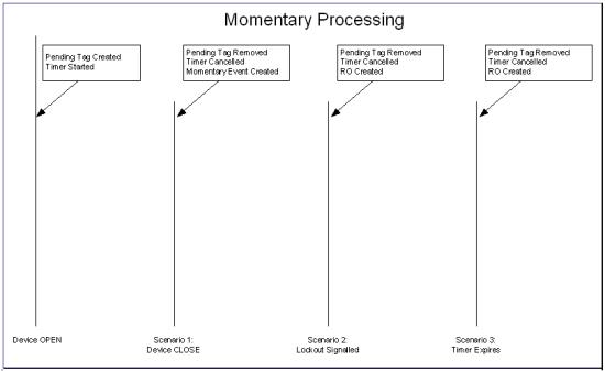
Note: RO (Real Outage) is created only if customer supply nodes are de‑energized as a result of the operation.
Once an RO is created, the FLISR processing sequence shown in the following figure is initiated.
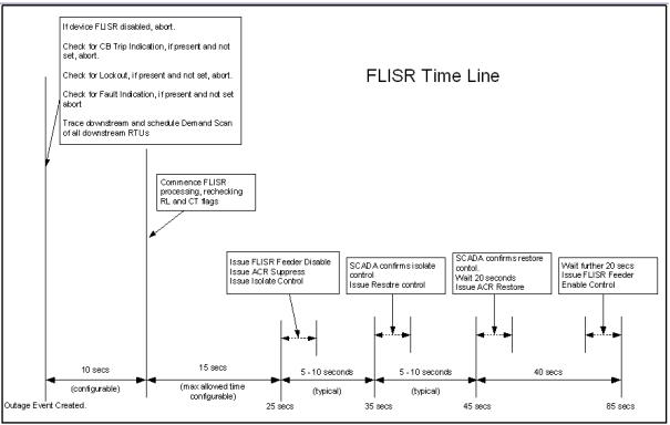
The control sequence (starting at around 25 seconds) is only performed in automatic mode. In manual mode an operator must initiate the control sequence.
Timings in the above diagram are only indicative. Actual values will depend on the complexity of the solution required and the responsiveness of the isolate/restore controls sent to SCADA. The following timings are deterministic:
• The delay allowed for demand scans. This is configurable and defaults to 10 seconds.
• The maximum solution time allowed in automatic mode. This is configurable and defaults to 15 seconds. If the solution takes longer to solve than this time, FLISR will not automatically execute the control sequence. The option for an operator to manually initiate the control sequence is preserved.
• Maximum time allowed for automatic operations after the lockout is: Demand scan delay + maximum solution time. The default configuration is 25 seconds.
• Wait times for Recloser operations. These are 20 seconds.
• Any error conditions detected during process are logged in the Event Log.
Understanding FLISR Voltage Loss Detection Triggers
FLISR responds to devices reporting loss of voltage. In the event of a device reporting loss of voltage, FLISR traces upstream of the reporting device to figure out the top level device that is experiencing the loss of voltage. Sub-station breakers should be inherited from flisr_sectionalizer inheritance and should be configured as protective devices for FLISR to process them.
After determining the top level device, FLISR creates a PDO and assumes that the fault is between this device and the first SCADA sectionalizer below it. FLISR opens the SCADA device and restores the downstream section using the tie switches.
When FLISR detects a device reporting loss of voltage, it waits for momentary processing and then checks whether the device is reporting currents and voltages below the threshold. FLISR is able to process this scenario for single-phase or multi-phase fault events. If FLISR determines that the fault is in the substation, it waits for a configurable amount of time (default 180 seconds) before starting its processing.
Note: The thresholds, momentary processing time, and desired FLISR mode in this scenario can be configured using the FLISR Voltage Loss Thresholds SRS rule. Substation restoration delay time can be configured using FLISR Sub-Station Restoration Delay SRS rule.
Understanding FLISR Blocking Conditions
NMS may be configured with conditions to block FLISR actions when present. Any FLISR regeneration plan that would include the condition will be excluded from automatic actions or from suggested restoration plans.