Schematics
Oracle Utilities Network Management System– Schematics can automatically generate orthogonal schematic overviews of the nominal network.
Model Requirements for Schematics
In order to use Oracle Utilities Network Management System Schematics, the following is required of the data model:
• All substations must have the same partition class.
• The substation partition class must only be used by substations.
• All boundaries between feeders and substations are designated with a distinct class of devices.
Schematic Limitations
Since Oracle Utilities Network Management System Schematics uses a splayed-tree representation of the nominal network, it is necessarily geared towards radial networks and will have difficulty representing nominally looped, parallel or meshed areas. Oracle Utilities Network Management System Schematics is also geared towards simple network objects (for example, a switch) and cannot keep related devices in close proximity (for example, the internals of a switching cabinet).
Configuring Schematics
All schematic configuration is done through Configuration Assistant's Schematica Options Tab and the configured options are stored in a database table called schematic_options. Default options are populated by [project]-schematica.sql file. The script that contains the configuration of the default option packages to be executed is called [project]-create-schematics.
The script performs these three actions:
• Remove any previous schematic import files.
• Call schematica to execute a particular option package.
• Process all generated import files.
The schematic generation is triggered from the Configuration Assistant by passing the option package and selected maps that invokes a script called nms-schematics, which in turn invokes schematic-generator (schematica) where all the options of the selected option package are queried from the table and executed. See "Using the Schematica Options Tab" section in the Oracle Utilities Network Management System User's Guide Configuration Assistant chapter for more information.
Script nms-schematics can also be run through command line by passing the arguments ‑schoption, option package and the -maps, the list of schematic map filenames (excluding file extension) that should be rebuilt, with spaces between the map names. Only these maps will be rebuilt. If -maps is not provided then the schematic generation applies to all the maps by default.
nms-schematics -schoption <option package> -maps <list of map names>
The following table describes all of the options that can be configured through Schematica Options tab, organized categorically.
Execution Options
Option Name | Description |
dbname | db <DBService prefix> | Force the schematic-generator to use the DBService that has the specified prefix (db MB will use MBDBService). |
feederPrefix <comma-delimited list ofstrings> | Only process substations whose map names contain the specified strings. |
classesToLabel <list of classes> | List of classes for which the schematic-generator should create and place annotation. |
switchgeardevices <list of classes> | List of device classes for which schematic-generator should identify as switchgear devices. |
switchgearcolumnname <column name> | Column name of the base table for switchgear device classes, in which switchgear device name is populated. This switchgear device name gets displayed as annotated text over switch gear symbol. |
switchgearsymbolclass <class name> | Class number of switchgear symbol which gets displayed on switchgear devices. |
coordSystem <#> | The coordinate system the schematic generator will assign all schematics. Should not be an existing value. Defaults to the current maximum coord_system + 1. |
placeSubsByConnection | Attempt to position substations with the greatest number of common connections closest to each other. |
separateCoordSystems | place maps in separate coordinate systems |
invisibleClasses <list of classes> | List of classes (that never have symbology, i.e., zeroimpedence conductors) that the schematicgenerator should ignore when attempting to connect a feeder to its parent substation. |
overviewName <string> | The names of all resulting schematic maps will take the form: <map prefix>_<overview name>_<substation name>. |
feederNameTable <table name> <column name> | The specified table for each feeder’s FID, annotated with the value found in the specified column. For single-circuit schematics, the feeder name is used as part of the generated map’s name. |
ptns | A list of the partition numbers to query, rather than querying the entire model. This is used internally by MBService to process model edits quickly and should generally not be used in other cases. |
deltasOnly | Only rebuild the specific maps that have changed since the last schematics build. Use this in your [project]-postbuild script if you feel that processing all schematics is too performance-intensive at the end of your model build. |
Feeder Extent Options
Option Name | Description |
fbdbounded | Use this option if all feeder-heads have FID on one port and an FBD on the other. |
ignoreunconnectedopenpoints | Treat any open switch that has no connections on either port as if it were a regular switch when determining what devices to prune from the feeder schematic. |
singlecircuitstartclass | The single circuit schematic map can only start with one of these device classes. Choose these carefully and model circuits consistently. The resulting map name for this map will be the name of the FID that feeds this device. |
startAtFID | Use when all feeder heads are modeled to have an FID attached. |
stop <list of classes> | List of all device or node classes the schematicgenerator should not trace past. |
substationTransitionClass <list of classes> | The set of classes that designate the transition between feeder and substation. Defaults to hyper_node. |
validFeederStartClass <list of classes> | List of classes that designate the start of a feeder. Required. |
voltage <minimum voltage> <max voltage> | Only process devices that fall into the specified voltage range. |
Feeder Grouping Options
Option Name | Description |
nosubstations | Do not draw substations. Instead draw all feeders in the same map in one or more rows. This option is only used when drawing all feeders in one map. To draw each feeder in a separate map, do not use this option; use the substationName with an argument to group by feeder_name. (see maxRowWidth) |
geographicSubstations | -gs <table name> <column name> | Use this option when all substations are modeled in the geographic world. Schematica will search the specified table for all classes listed in substationNodeClasses and set the substation name based on the value in the specified column. Note: This option must be used in conjunction with substationNodeClasses. |
substationName <database table name> <table column name> | Do not model substations. Instead, search the specified table for each feeder’s FID and group them into substations based on the values in the specified column. For example, if the column is the feeder_name column, each feeder will have its own schematic map. It could also be the substation_name, which would group all feeders form one substation together. Or it could be any other column in the specified table or view, as desired. |
Layout Options
Option Name | Description |
branchWidth <dist> | Distance between two network branches that share a common upstream port. (see Figure 1 below) |
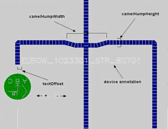
camelHumpHeight | Relative height (in terms of tier-height) of conductor crossover bumps. Value between 1 and 0. (See Figure 4 below) |
camelHumpWidth | Relative width (in terms of branchWidth) of conductor-crossover bumps. Value between 1 and 0. |
deviceHeight <#> | Size of all non-conductor electrical branches. (See figures following this table.) |
excluded <class name> | Any classes specified here will be excluded from the generated schematic map with the exception of tie devices which will appear in the schematic view. |
feederTextScale <#> | Amount to scale all feeder-name annotation. |
feederHeight <#> | Minimum distance between a substation and the first device of a feeder. (See figures following this table.) |
feederOffset <#> | Distance between adjacent feeders. Default is branchWidth*10. (See figures following this table.) |
globalScaleFactor <#> | Increases the size of all objects and all overviews by this amount |
noFeederToFeeder | Do not connect up feeder-to-feeder tie-points. (See figures following this table.) |
noIntraFeederConnections | Do not connect up bypass tie-points. |
nosubtosub | Do not connect up sub-to-sub tie-points. |
scaleFactor <#> | Multiplies the size of all conditions by this amount. |
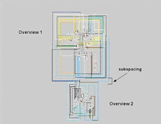
subSpacing <#> | Minimum distance between substations. No default. (See figures following this table.) |
substationBoxSize <#> | Create a square of the specified size and scale the original substation schematic to place inside. Default is 1000. (See figures following this table.) |
substationTextScale <value> | Amount to scale the size of the substation label. |
tapDeviceOffset <value> | Distance to offset single devices from the main trunk. |
textScale <#> | Scale all device annotation by this amount. |
textScaleSubstationDevices <value> | Amount to scale the text size for substation device annotations. Default value is 1.0. Alternative name is tssd. |
textOffset <#> | Distance (along the feeder’s main axis) to pull all device annotation. Default is 0. (See figures following this table.) |
tierHeight <#> | The distance (along the feeder’s axis) a conductor will span. Default is 50. (See figures following this table.) |
weightClass [<class name> <weight>…> | Tells the schematic-generator to process certain classes of objects sooner when creating its internal schematic tree. If weight < 0, process later. If weight > 0, process sooner. |
Advanced Layout Options
Option Name | Description |
balancesubstations | Shift feeders around a substation until there are similar NUMBERS on each valid side. |
defaultConductorSymbology <valid symbol class> | Use this symbol class when attempting to write out any conductor that has a symbol class of 0. |
defaultFeederDirection <north|south|east|west> | If the schematic-generator is unable to determine the direction for a feeder, it will use this value. No default. If this option is NOT specified, the schematic generator will ignore any feeder for which it cannot determine a direction. |
deviceGaps <class name> <scale factor> | Scales all diagrams of the specified classes by the specified amounts. |
deviceScaling <class name> <scale> <offset> | Scale all diagrams of the specified classes as well as shift them along their parent feeder’s axis. Default scaling is 1.0, default offset is 0.0. |
fastcrossovers | Use a faster, but less accurate algorithm to determine where conductors intersect. |
feederDirection <north|south|east|west> | Have ALL feeders extend in the specified direction. |
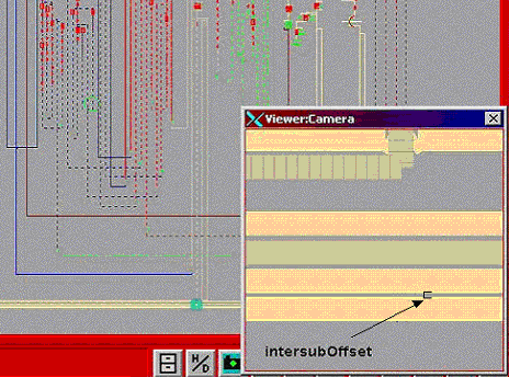
intersubOffset <#> | Minimum distance between parallel sub-to-sub conductors. Defaults to tier-height or deviceheight* 2, whichever is greater. (See figures following this table.) |
maxRowWidth <#> | the maximum width of each row of feeders |
allSubstations | The allSubstations option will force the inclusion of all substations even if they do not have interconnected feeders or any feeders at all. |
noPrune | Keep all devices in a feeder, not just those attached to open-points. |
noPruneCls <list of classes> | Keep all spurs that contain devices that belong to the list of classes. This option is unnecessary if running noPrune. |
noPrunePhysProperty <bitwise physical property integer> | Prevent devices with certain physical properties from being pruned. This is likely useful if you suspect that certain properties are not used consistently in the model and you want to be sure the schematic has, for example, all backbones, even if they are downstream from laterals. The integer argument is a bitwise OR of all the network_components.physical_properties bits that you want to prevent from being pruned. |
noPruneSCADA | Keep all spurs that contain SCADA devices. This option is unnecessary if already running noPrune. |
Orientation <ANY|HORIZONTAL|VERTICAL|ROUND_ROBIN|NONE> | Align all feeders according to the value. (ANY = normal feeder directions, HORIZONTAL = move all north/south-ward feeders to east/west, VERTICAL = move all east/west-ward feeders to north/south sides, ROUND_ROBIN = evenly distribute the feeders around the substation, NONE = move ALL feeders to side specified by "feederDirection") Default is ANY. |
overlapConductors | Extend conductors to the center of adjacent switches. Default: false. |
priorityClasses <list of classes> | Keep the specified list of classes as close to the main trunk of the generated schematic tree as possible. |
reorientDeviceClasses <list of classes> | Ensure that diagrams for the specified classes are always oriented from left to right. (Use this if symbols appear upside-down.) |
skipEmptyFeeders | Do not draw feeders that contain an exceedingly small number of devices (< 10 devices) |
sort <GEO|SPAN> | Arrange feeders either geographically (using only the anchor points of each feeder) or arrange them to minimize the distance feeder-to-feeder tiepoint connections must span. Values: GEO|SPAN • GEO: geographic ordering, • SPAN: minimal spanning tie points. Default is GEO |
Class Specification Options
Option Name | Description |
boundingBoxCls <class name> | Create a box of this class to indicate the substationoverviews extents. If unset, the box is not drawn. |
boundingBoxLabelCls <class name> | Create a label of this class, with the substation’s name. Default is branch. |
connectionClass <class name> | Device class to use when creating a branch to span two or more non-conductor devices. (Must be a nonelectrical branch) |
labelClass <class name> | Use this text class when creating device annotation if the class <device_class_name>_t2 does not exist. Text class to use for all generated annotation. (See figures following this table.) |
substationBoxCls <class number> | Create a box of this class-type around the substation. No default. If not specified, there will be no visible box around the substation. (See figures following this table.) |
substationPtnCls <#> | Only process substations with this specific partition class. No default. |
The following figure shows the deviceHeight, branchWidth, and feederOffset.

The following figure shows substationBoxSize, feederHeight, tierHeight, and connectionClass.

The following figure shows a feeder-to-feeder connection.

The following figure shows camelHumpWidth, camelHumpHeight, device annotation, and textOffset.
The following figure shows subspacing.
The following figure shows intersubOffset.
Schematic-Specific Symbology
Populate the new schematic_symb_class database table with any symbology state classes you wish to use in the auto-generated schematic maps. Use this if you want devices or conductors to appear different in the schematic maps than they do in the nightly build maps.
Note that this is non-product configuration; product does not add any schematic-specific symbology state classes to this table.
Generating Schematics
To create schematics, the customer-specific script [project]‑postbuild must have a call to [project]‑create‑schematics.
The Post-Build Process
After the build process has processed the final map, it calls nms‑postbuild. If there is a [project]‑postbuild script, nms‑postbuild will call it. If there is an entry for create-schematics, it calls it at this time.
Creating the Import Files
Once invoked, the schematic generator loads in the entire nominal network model and attempts to group all feeders with their parent substations. After it finishes determining the layout and spacing for all feeders and substations, it writes out one import file for each substation.
Processing the Import Files
After the schematic-generator creates the import files, the schematic script compares the most recent previous version of each file. If no changes are detected, it skips the map. Otherwise it proceeds to build the import file as per the normal model-build process.