View Menu
Options available here provide different views of the electrical network:
• Color by Feeder: When selected, colors the network feeder by feeder.
• Color by Phase: When selected, colors the network by phase.
• Color by Nominal Voltage: When selected, colors the network by nominal voltage.
• Color Secondary by Color Mode: When selected, displays the secondary network by the currently selected “Color by…” option.
• Color Secondary by State: When selected, displays the electrical state of the secondary network.
• Show Nominal Network State: When selected, displays the nominal state of devices and conductors.
• Declutter Symbols: When selected, declutters the network when zoomed out.
• Map Color Legend: Displays the Map Color Legend dialog, which illustrates the colors, highlights, and line styles for the different electrical states, phases, and voltages.
• Show Diagnostics Panel: Displays a panel allowing access to Map configuration and analysis (not displayed for most User types).
Map Hide/Display Options
The Hide/Display menu allows you to select what devices or map components to show or hide. The options are:
• Hide / Display
• Landbase: Toggle the visibility of the Landbase (if one is selected in the Settings panel).
• Secondary: Toggles the visibility of the Secondary network
• Structures: Toggles the visibility of structures such as poles
• Non-Main Asset DA: Toggles the visibility of non-main asset damage report symbols.
• Annotations
• Conductor Current Phase Markers: Toggles the visibility of phase indicators on conductors.
• Device Labels: Toggles the visibility of device labels
• Device Nominal Phase Labels: Toggles the visibility of devices’ nominal phase(s). If a device is in an abnormal state the background of the label is colored green (abnormally open) or red (abnormally closed).
• Conductor Nominal Phase Labels: Toggles the visibility of conductors’ nominal phase(s). If a conductor is in an abnormal state the background of the label is colored green (abnormally de-energized) or red (abnormally energized).
• Conductor Feeder Labels: Toggles the visibility of conductor feeder labels.
• Flow Direction: Toggles the visibility of flow direction arrows.
• Crews Types
• All
• Line
• Trouble
• Guide
• Service
• Eval
• Tree Crew
• Conductor Highlight
• Assessed
• Predicted De-Energized
• Confirmed De-Energized
• Confirmed Degraded
See Hiding and Displaying Viewer Objects on page 2-79 for more information.
Using the Map's Back and Forward Buttons
The map toolbar Back ( ) and Forward (
 ) buttons allow you to go back or forward to recently viewed positions on the map. The history is stored whenever the Map is stationary for a couple of seconds. Up to 50 map positions can be stored in history.
) and Forward () buttons allow you to go back or forward to recently viewed positions on the map. The history is stored whenever the Map is stationary for a couple of seconds. Up to 50 map positions can be stored in history.When smooth animation between positions is enabled, there may be some occasions where you want to skip the animation and proceed directly to the target. Selecting this option ( ) performs that action.
) performs that action.Searching and Positioning
You can search on assets, customers, and other type of map object.
1. Click the Search button ( ) to open the Map Search dialog box.
) to open the Map Search dialog box.2. Choose the Search Type from the drop‑down list.
3. Enter the text to search for.
4. Select a wildcard option, if applicable.
5. Click the Search button to execute the search:
Search button to execute the search:• If there is only one match, the dialog box will close and the Map will reposition.
• If there are multiple matches, they will be displayed in a Search Results dialog box. Select a row in the Search Selection Results dialog box and click the Select button ( ) to select and position the Map on that item.
) to select and position the Map on that item.Using the Distance Measurement Tool
You can measure distances on the Map:
1. In the Map toolbar, click the measurement tool ().
2. Click in the map to add a start position.
3. Move to a different position and click again to create a turning point.
4. Double-click or click on the last point to complete the measurement. The distance is displayed in the top-right corner of the Map.
5. Click anywhere in the Map to remove the measurement.
Using the Geographic Location Tool
You can click on a map location to get the geographic co-ordinates:
1. In the Map toolbar, click  .
.
.2. Click in the Map at the desired location. The geographic co-ordinates are displayed in the top-right corner of the Map.
3. If required, copy the co-ordinates to the clipboard.
4. Click anywhere in the Map to remove the co-ordinates.
Displaying Tooltips
You can display hover-over tooltips:
1. In the Map toolbar, click  .
.
.2. Mouse over a device, conductor, or symbol to reveal more information.
To keep the tooltip displayed, move the mouse pointer over the tooltip while it is still displayed. The information displayed depends on the type of object.
Selecting and Interacting with Map Objects using the Selection Panel
When you select a device or symbol, it will be highlighted or outlined in yellow [1]. The Selection Panel will be displayed [2] when the Selection Panel icon is toggled on [3]. Device operations are available through right-click context menus [4].
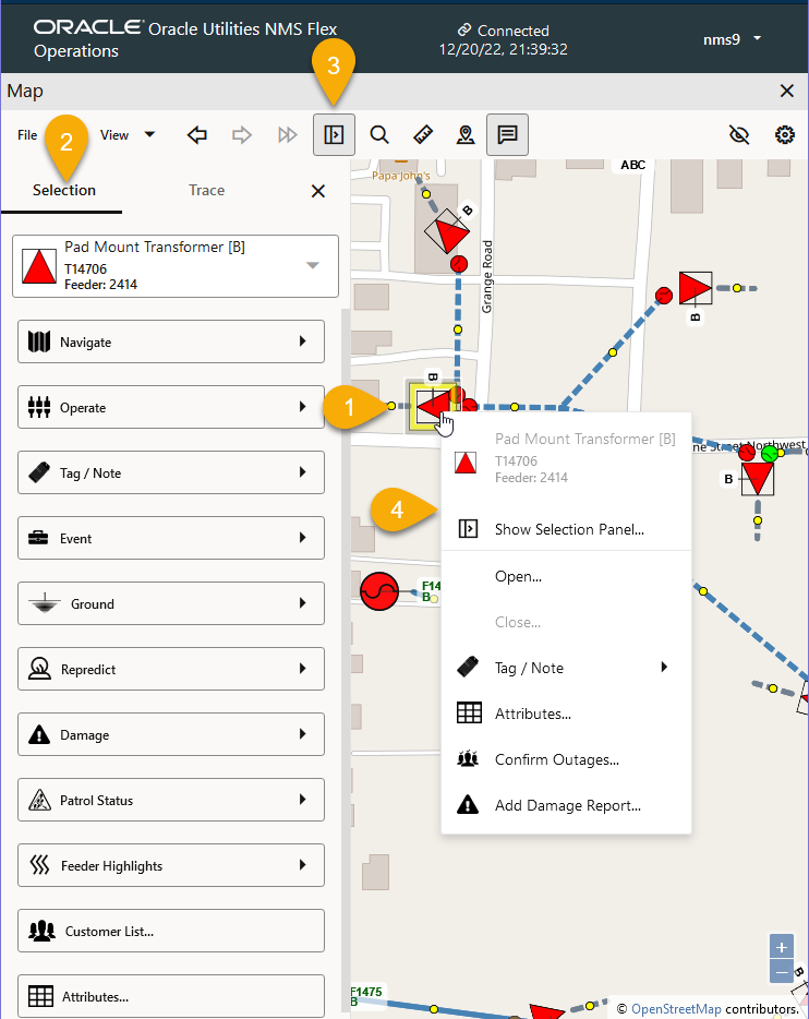
The Selection Panel is a combination tool providing actions and information that are found in multiple tools in the NMS operations client (for example, the Control Tool).