Viewer Power Flow Information Visualization
In addition to the standard feeder and phase views, the Viewer provides options for visualizing the power flow information. The Viewer Legend, which is opened from the Help menu, displays legend information based on the view selected in the Viewer's Options menu.
.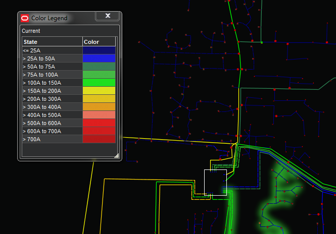

Currents: the current range
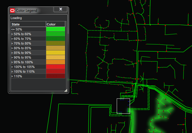
Loading: the per unit current range.
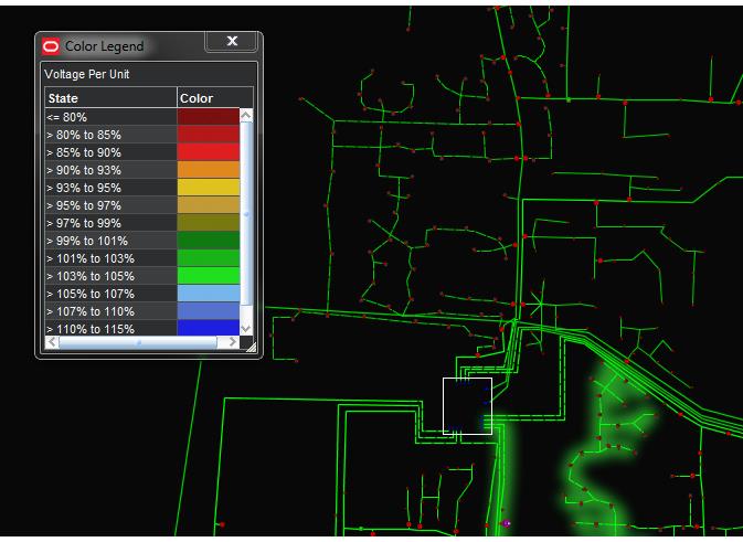
Voltage Per Unit: the per unit voltage range.
Note: If a feeder is solved in kVA mode, then the voltage will be constant.

Nominal Voltages: the nominal voltage range.
Note: If an area of the model is set as Power Flow Disabled the voltage configured within database table NETWORK_COMPONENTS will be utilized instead.
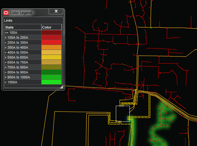
Limits: conductor Amp limits.
Flow Direction
The Viewer will render any of the view options with flow direction by selecting Show Flow Direction from the Viewer's Options menu (Shift-D). The example below shows Feeder with flow direction enabled..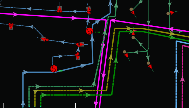

While the power flow is solving, or when a solution has failed, hash marks are displayed instead of arrows. Because this is a power flow solution, looped and parallel areas can still display flow direction arrows. These arrows will point to the equilibrium spot. If power flow is not licensed, the arrows will show a simpler topological flow that cannot detect an equilibrium point.
Line Catalog Information
The Line Catalog Information dialog box displays power flow line catalog information for a conductor selected in the Viewer. To see the Line Catalog Information, select a conductor, launch its Control Tool, and click the Line Catalog Info... button.
The dialog box has two panes containing the following information.
Top Pane
The top pane displays the following information:
• Class: The device class description.
• Name: The conductor ID.
• Voltage: The nominal conductor voltage (line to line).
• Length: The conductor length.
Lower Pane
The lower pane displays information related to the power flow line catalog:
• Conductor Catalog: The identifier for a conductor impedance catalog defined within the Oracle Power Flow Engineering Data Workbook.
• Data Source: The method in which the data was provided within the Oracle Power Flow Engineering Data Workbook. The possible methods for providing data are:
• Construction Parameters
• Phase Impedance
• Sequence Impedance
Note: If the Construction Parameter method was used for a particular catalog, four additional fields will show up to display the different phase and neutral conductors that make up the catalog.
• R1: The positive sequence resistance of the conductor catalog.
• X1: The positive sequence reactance of the conductor catalog.
• R0: The zero sequence resistance of the conductor catalog.
• X0: The zero sequence reactance of the conductor catalog.
• Ph A Line Catalog: The conductor type used for phase A (only displayed if the Data Source was Construction Parameters).
• Ph B Line Catalog: The conductor type used for phase B (only displayed if the Data Source was Construction Parameters).
• Ph C Line Catalog: The conductor type used for phase C (only displayed if the Data Source was Construction Parameters).
• Neutral Catalog: The conductor type for the neutral (only displayed if the Data Source was Construction Parameters).
• Limits: Will show either the temperature or seasonal based limits for the conductor depending on how the project has setup the limit configuration.
• <Season or Temp Band> Normal Limit: The normal ampere capacity limit for the conductor for the specified season or temperature band.
Note: Ampere Capacity may also be referred to as ampacity.
• <Season or Temp Band> Emergency Short Limit: The short term emergency limit for the conductor for the specified season or temperature band.
• <Season or Temp Band> Emergency Long Limit: The long term emergency limit for the conductor for the specified season or temperature band.
Note: The number of configured seasons or temperature bands can change based on project configuration (for example, yearly ratings, four seasons, ten temperature bands, and so on).