Using the State Transitions Tab
In Oracle Utilities Network Management System, events, switching sheets, safety documents, and damage assessment pass through different phases over their lifecycle. These phases are represented by states. Transitions between states are knows as state transitions. A transition between any two states happens when certain actions are performed by a user or the system.
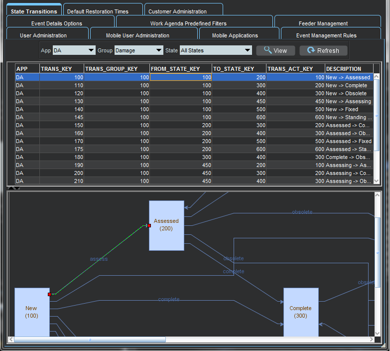
The State Transitions tab allows you to view the state transitions of events, switching sheets, safety documents, and damage assessment in tabular and graphical views. The tab is divided into 3 panes:
• Selection Pane
• Tabular Section
• Graphical Section
1. Selection Pane
State transitions in NMS are divided logically into multiple groups. The highest level division is based on the application (APP); the second level is based on sub-categorizations of the applications into groups (Group); the last level are states applicable to the application group.
Filter Options Menus
• App: the application type option menu lists codes for the NMS applications with state transitions:
• DA: Damage Assessment
• SF: Safety
• TE: Trouble Events (generic for events)
• WSW: Web Switching
• Group: the group selection lists the available groups for the selected application. For example, if the application is TE, you may select OUT for outage events.
• States: the states selection lists the available states for the chosen app-group combination. In addition to the specific states selection, you may choose All States to see all state transitions for the app-group combination.
Buttons
• View: Based on the selection of different combo boxes, on clicking this button, it will display the filtered set of transitions in table and graphical view.
• Refresh: Refreshes the data by reading from the database table, but retains previously selected filters by user.
2. Tabular Section
The table displays transitions in tabular view and contains following columns:
• APP: Application name
• TRANS_KEY: unique key of transitions
• TRANS_GROUP_KEY: transition type (OUTAGE/MEET).
• FROM_STATE_KEY: unique value for state (from).
• TO_STATE_KEY: unique value for state (to).
• TRANS_ACT_KEY: unique value for action.
• DESCRIPTION: description of this state transition.
3. Graphical Section:
The transitions from the table are displayed in a hierarchical view in this section. States are displayed as rectangular boxes labeled with the state name. Transitions are displayed with arrow symbols beginning at the from state and ending at the end state with the action name of the transition on top of the edge. When you select an arrow in the graphical view, the corresponding table row will be highlighted.
Viewing State Transitions
To view state transitions, do the following:
1. Select the application from the App options menu.
2. Select the group from the Group options menu.
3. Select a specific state from the State options menu.
4. Click View.
The table and graph will be updated for the state transitions applicable to your selection.
Example: New Damage Assessments State Transitions
1. Select DA from the App menu.
2. Select Damage Assessment from the Group menu.
3. Select New from the State menu.
4. Click the arrow that starts at the New box and ends at the Assessed box.
