1 ODT Application Full Deployment
This topic describes the steps to deploy Open Development Tool application into WebLogic server in full deployment mode.
- Start Oracle FLEXCUBE Universal
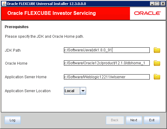
Installer.The Oracle FLEXCUBE Universal Installer is displayed.
Figure 1-1 Oracle FLEXCUBE Universal Installer
- On Oracle FLEXCUBE Universal Installer
screen, enter the following details.Refer to the table for JDK and Oracle Home path.
Table 1-1 JDK and Oracle Home path
Field Description JDK Path Provide Home folder path of JDK1.8.
Oracle Home Provide home folder path of Oracle Client or Database.
Application Server Home Provide home folder path of Application Server.
Application Server Location Select location of the application server either local or remote.
- Click Next to select the option for installation.
- Select Open Development Tool from the
lists of Oracle FLEXCUBE
options.The available options for installation are displayed.
- Click Next to choose Oracle FLEXCUBE component for installation.
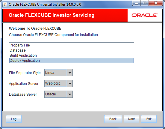
- Select Deploy Application.The available options Property File, Database, Build Application, and Deploy Application are displayed.
Figure 1-2 Oracle FLEXCUBE Component for Installation in Full Deployment
- Select the appropriate operating system from the File Seperator Style drop-down.
- Choose Weblogic from the Application Server drop-down.
- Select the appropriate DataBase Server from the drop-down and click Next.
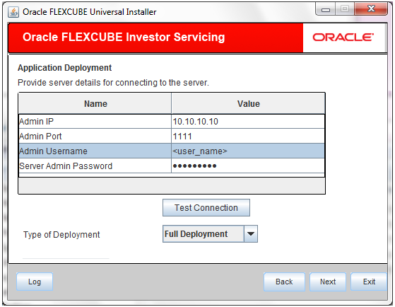
- Specify Server details to connect to the server and click
Next.Refer to the table for server details.
Table 1-2 Server details
Field Description Admin IP Provide host address of Admin server.
Admin Port Provide port number of Weblogic server.
Admin UserName Provide the appropriate Admin Username of the Weblogic Application server.
Admin Password Provide the appropriate Admin Password of the Weblogic Application server. Type of Deployment Choose Full Deployment.
The following screen is displayed.Figure 1-3 Server Details for Full Deployment
- Click Test Connection to test the
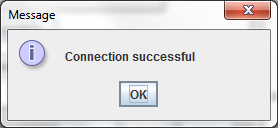
connection with the Application server.On successful connection, the following message is displayed.
Figure 1-4 Information Message on Successful Connection
- Click Ok and click
Next in the installer.The following screen is displayed.
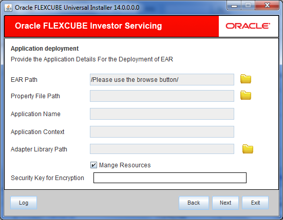
Figure 1-5 Application Details for Full Deployment
- Specify Application details to deploy the EAR.Refer to the table for Application details.
Table 1-3 Application details
Field Description EAR Path Select the application EAR to be deployed using the Browse button.
Note: The Application EAR path cannot be copied and pasted on to the text box, thereby demanding the use of the Browse button to select the EAR.
Property File Path Select the appropriate path to the external properties file.
If the properties file is internal to the application EAR, it would be fetched on selection of the EAR and will be in a non-editable state.
Application Name Selection of the EAR would fetch the Application Name and it will be in a non-editable state.
Application Context Selection of the EAR would fetch the Application Context and it will be in a non-editable state.
Adapter Library Path Selection of the EAR would fetch the Application Library Path and it will be in a non-editable state.
Manage Resources Select this box if resources are to be created along with deployment.
- Click Next. If Manage Resources is not checked, you can continue to provide Server Environment details for deployment.
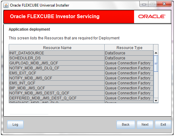
- Select Manage Resources box if resources
are to be created along with deployment.The screen provides a read only list of resources.
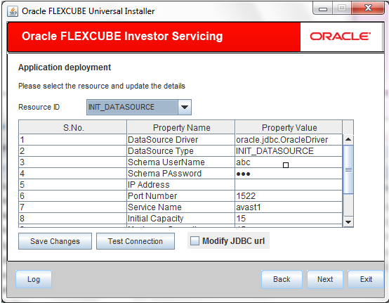
- Specify the resource details that are required for
deployment.Refer to the table for resource details.
Table 1-4 Resource details
Field Description Resource ID Specify Resource ID. Also, you can select the resource from a list of data sources maintained and update the details.
DataSource Driver Specify the JDBC driver URL with which the connection is to be established.
Ex: oracle.jdbc.OracleDriver for Non-XA datasources
DataSource Type Specify the type of datasource that is to be created, XA or Non-XA.
Schema Username Specify the username of the schema to which the connection is to be established.
Schema Password Specify the password of the schema.
IP Address Specify the host address of the schema.
Port Number Specify the port number of schema.
Service Name Specify the service name of schema.
Initial Capacity It is the number of physical connections that can be created when creating the connection pool in the data source
Maximum Capacity The maximum number of physical connections that this connection pool can contain. Capacity Increment The increment by which this JDBC connection pool's capacity is expanded. Shrink Frequency The number of seconds to wait before shrinking a connection pool that has incrementally increased to meet demand. Connection Reserve Timeout The number of seconds after which a call to reserve a connection from the connection pool will timeout. - Click Test Connection to establish connection with required details provided in the table against corresponding value of Resource ID.
- Click Save Changes to save the values provided in the table against corresponding value of Resource ID.
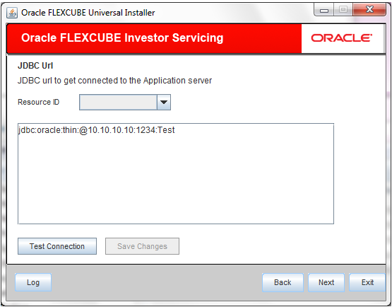
- Select Modify JDBC Url to modify the
provided JDBC url.If Modify JDBC Url is selected, the following screen is displayed.
- Specify Resource ID and click
Test Connection to check the
connection using the changed Url. If the Url changed is
correct, then the successful connection will be made. Click
Save Changes to save the
changed JDBC Url.
Resource ID: It provides the list of all the datasources created. Select the data source for which the JDBC Url needs to be modified.
Note: The JDBC Url generated from the previous screen will be displayed here. If the user wants to change the JDBC Url, it can be changed in the current screen.
- Click Next after the resource details
are updated.The following screen is displayed.
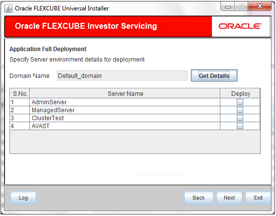
- Specify Server Environment details for deployment.The Domain Name shows the weblogic domain name.
- On Server Environment details screen, click Get
Details button.The list of available servers are displayed. Atleast, one server should be selected to proceed.
Figure 1-9 Server Environment Details for Full Deployment
- Click Next after the server environment
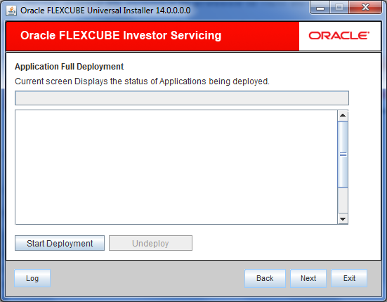
details are specified.The following screen is displayed.
Figure 1-10 Application Deployment Status for Full Deployment
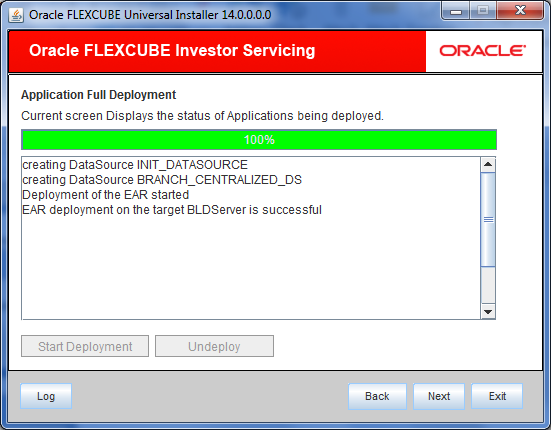
- Click Start Deployment to start the
process of application deployment.The following screen displays the status of Applications being deployed.
Figure 1-11 Start Application Full Deployment
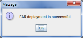
- You can view the information message on successful deployment
and click Ok in the
Message window.The following Message window is displayed.
- Click Undeploy button for undeploying
the partially deployed EAR from the server.If the deployment is not successful, the Undeploy button will be enabled in the Application Deployment status screen.
