Live Energy Connect Concepts and Terminology
This section provides a list of concepts and terms used to describe Oracle Utilities Live Energy Connect (LEC) configurations. Some of these terms are specific to LEC, and some terms originate from industry protocols and standards.
On this page:
ICCP and MMS
The Inter-Control Center Communications Protocol (ICCP), also known as TASE.2, is a protocol that allows for real-time data exchange between utility systems over WANs or LANS. The ICCP standard is maintained by the International Electrotechnical Commission as IEC 60870.
For more information about ICCP, see ICCP Reference.
ICCP itself is built on top of the Manufacturing Message Specification (MMS) standard, which is maintained by International Standards Organization as ISO 9506. MMS defines a standard for data exchange consisting of real-time monitoring and control data between two devices.
The design and organization of LEC is very much influenced by MMS. Much of the high-level organization finds its origins in MMS concepts. This means that many of the rules of LEC find their origin in the MMS specification. For example, MMS variable names can only consist of 32 characters and can only contain the alpha-numeric characters and underscores (character ‘_’). This rule is enforced in LEC for explicit input and output ICCP points. For more information about MMS refer to the ISO’s website.
VMD
LEC uses the MMS concept of Virtual Manufacturing Devices (VMD’s) to represent component devices and systems. For example, a VMD on in an LEC Server configuration might represent a VCC (a VMD in the ICCP protocol) or a device from an entirely unrelated protocol, for example: A DNP master station, a Modbus slave, or an OPC UA server.
Each type of VMD in an LEC configuration is associated with a specific type of communication protocol or application interface, for example: ICCP, DNP, Modbus, ODBC, etc.
A VMD within an LEC Server configuration can connect to a device that exists outside of the LEC Server or to the other VMD’s within the LEC server. VMD’s allow LEC to capture, transform, and route data to devices, systems, or applications in a form that the other devices, systems, or applications can understand.
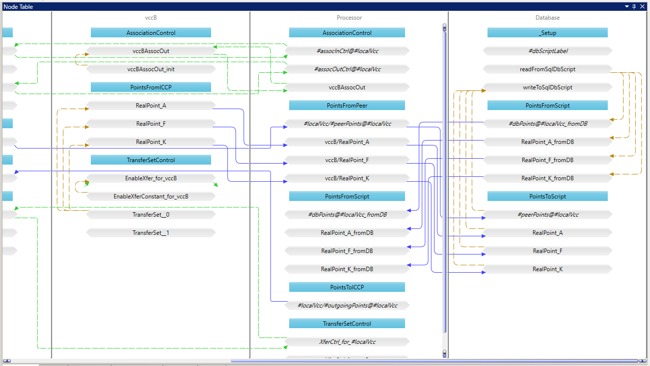
In the LEC Configuration Manager, VMD’s are displayed as vertical rectangular panels. In the above figure, the LEC Configuration Manager is displaying three VMD’s: vccB, Processor, and Database.
Configuration Aliases
The LEC Configuration Manager uses Configuration Aliases to organize and manage multiple LEC server configurations on the same machine. Each configuration created, edited, or viewed in LEC Configuration Manager is associated with a particular Configuration Alias. Typically, customers will only use one LEC Server instance per machine in production. By convention, that configuration alias is named cfg.
Configuration Manager VMD
Each LEC configuration contains at least one VMD called the Configuration Manager VMD. It represents the local machine (the machine running LEC) as a VMD within the configuration. This VMD is used to define certain nodes that represent variables in the LEC configuration that are related to the local machine, like a system variable or the status of a TCP connection. Configuration Manager VMD’s are automatically created and named after the Configuration Alias and suffixed with the string _LDSMGR.
Points
Points are representations of measurements, states, signals, commands, or messages.
For example, your LEC Server configuration might have a point that represents the measured output of a power plant. Other points in your configuration might represent the temperature inside a transformer or the control signal to open a circuit breaker. Points live inside VMD’s. LEC orchestrates where these points come from, where they go, and it applies any required logic, filtering, or transformations along the way.
Nodes
A node is the representation of a point at a particular step in its dataflow through the LEC Server. In an LEC configuration, a single point is often associated with a number of nodes.
For example, if there is a point on a SCADA Server that represents the current through a line, then that point might start in the LEC Server configuration as a PointFromDnp node, get filtered in the Processor VMD as a DeadbandFilter node, and finally leave the server as a PointToIccp node.
Every node in LEC exists as an in-memory variable. Nodes are displayed in the Connections panel, the Node Table, and the Node Monitor.

In the above figure, nodes are displayed as gray horizontal bars inside VMD’s in the LEC Configuration Manager. The blue horizontal bars are just labels used to visually group nodes within a VMD called Combine Groups.
Connectors
A connector connects two nodes in an LEC Server configuration. It defines under which circumstances and in which direction data should flow between two nodes. Connectors are displayed as arrows in the LEC Configuration Manger. The types of connectors are: Implicit, Update, Demand, and Two Way.
Filter Nodes
A filter node is a special type of node in the LEC server. It is used to transform data or apply logic to the flow of data through that node. An example of a filter is the DeadbandFilter node. It is one of the many built-in filters that ship with LEC. This filter propagates data past itself (further along in the dataflow) if and only if the value of the data has changed by some configurable amount or percentage.
Prototype Configurations
Most LEC server configurations perform the same operations on large numbers of similar points. It is not practical to individually specify each node in the LEC Configuration Manager. Instead, you can use a Prototype Configuration as a model of the actual configuration. In a prototype configurations, VMD’s, nodes, and connectors in the configuration act as placeholders and templates. Prototype VMD’s and prototype nodes have names that begin with a ‘#’ character. At startup, the LEC Server populates all prototype
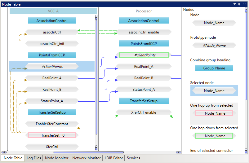
VMD’s, nodes, and connectors with actual VMD’s, nodes, and connectors using information provided to it in a batch file. The above figure shows the VCC_A VMD that contains a prototype node named #clientPoints. The RealPoint_A node in VCC_A is generated by this prototype node from information included in a batch file.
Batch File
A batch file provides the information necessary to populate any prototype VMD’s or prototype nodes with meaningful server configuration information.
Batch files are text files in CSV or JSON format that contain one or more tables. Each table has a header row with column values that correspond to various parameters of prototype VMD’s and prototype nodes in an LEC prototype configuration. Every other row in the table specifies the exact value of these parameters for an actual VMD or node in the dataflow. Connectors are not explicitly specified within a batch file. They are automatically built based on the connections between prototype nodes in the prototype configuration.
PDI Macros
PDI macros, sometimes referred to as just macros in LEC Configuration Manager menus, are pieces of reusable Programmable Data Interface (PDI) code used to define an LEC configuration. PDI is a declarative language created to define how data should flow through the LEC server. The LEC Configuration Manager uses a collection of PDI macros defined in a file called DataflowMacros.pdi at server start-up to implement server configurations defined in the Configuration Manager. Before the LEC had a GUI-based configuration tool, text-based PDI files were used exclusively to define configurations.
Each type of node, connector, and VMD in the LEC Configuration Manager corresponds to a PDI macro defined in the DataflowMacros.pdi file or a macro defined in a customer-specific PDI file or Python file. The parameters shown in the LEC Configuration Manager Properties panel are used as inputs for these PDI macros.