Creating an ICCP Client
Use the following steps to create an ICCP client.
On this page:
Step 1: Open an Empty Configuration
- Start the Oracle Utilities Live Energy Connect (LEC) Configuration Manager as an Administrator.
- Select Import Configuration from the File menu, and then select EmptyTemplate.db from the list of files in the C:\ProgramData\LiveEnergyConnect directory, and click Open.
- The Configuration Manager displays a warning that any unsaved changes to the current configuration will be lost.
- Click Cancel to save the current configuration in your desired location with an appropriate file name.
- If you do not need to save any changes to the last open configuration, click OK.
- The Configuration Manager may display a warning message indicating the EmptyTemplate.db configuration file contains PDI macros that are out of date. To update the macros, select Reload Macros from the File menu. A warning will appear saying the Configuration Manager needs to start the LEC Server. Click OK. The server will start up, reload any macros that need to be updated, and stop.
- Once the EmptyTemplate.db file has been imported, you will be able to see an empty LEC Server configuration in the Configuration Manager. It will have a single VMD- a Configuration Manager VMD.
Note: Every new configuration has a Configuration Manager VMD.
Step 2: Create a Processor VMD
The first VMD you need to create is a Processor VMD. Any local VMD in a configuration can communicate with any other local VMD using a Processor VMD as a proxy. The Processor VMD acts as the hub for your dataflow.
- Select ProcessorCreate in the VMD tab of the Templates panel.
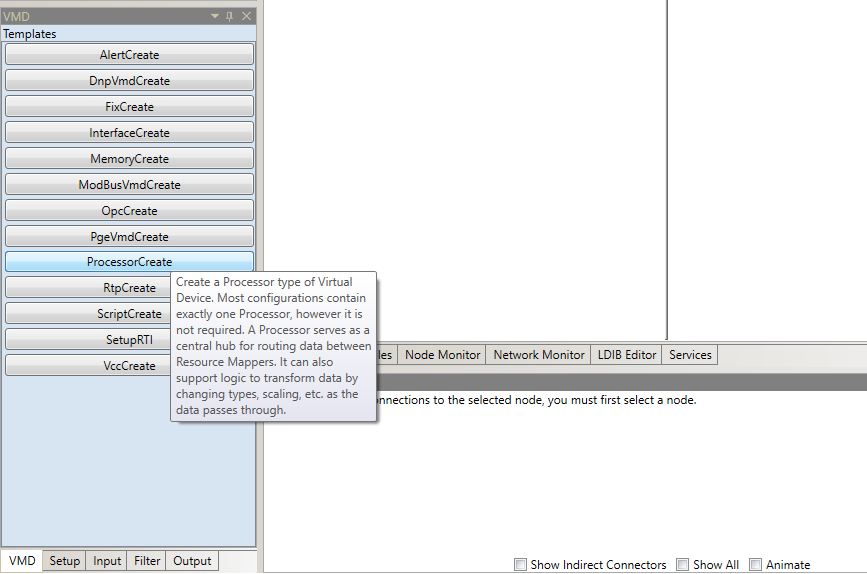
- In the Create VMD tool, specify Processor for the VMD name field.
- There is no need to enable any flags in the Flags field.
Note: The Flags field allows you to enable or disable certain functions in a VMD. The EXCLUDE_FLAG, ICCP_FLAG, PUSHALL_FLAG, and NOREAD_FLAG flags are set by default. To remove a flag, click Unset. To set a flag, click Set.
.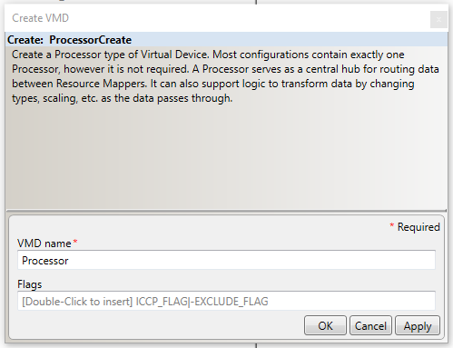
- Select OK to create the Processor VMD called Processor. Now there are two VMD’s in the configuration: a Configuration Manager VMD and a Processor VMD.
Step 3: Create a VCC
In LEC, a VCC is a type of VMD. The term VCC is originates from the ICCP protocol.
Note: The term VMD is specific to the MMS protocol. All VCC’s are VMD’s but not all VMD’s are VCC’s. The VCC VMD created here will serve as the ICCP client that makes an ICCP association with the remote SCADA system.
To make an ICCP association, both parties need to know certain parameters and information about their own VCC and the other party’s VCC. To learn more about setting up ICCP associations, see ICCP Reference.
Typically, when two parties are setting up an ICCP association they share the necessary ICCP association information with each other using an Association Information Exchange Form (AIEF). Since we are setting up both sides of our example scenario, we can just use the example values that are listed in the following table. For information about each parameter, see ICCP Reference.
| ICCP Association and Network Connection Info | Company A (our LEC Server) | Company B (SCADA Server |
|---|---|---|
|
VCC Name |
VCC_A |
VCC_B |
|
VCC Role |
Client |
Server |
|
Association Role |
Listener (makes inbound assoc.) |
Associator (makes outbound assoc.) |
|
Domain |
domA |
domB |
|
Bilateral Table ID |
1_0 |
2_0 |
|
ICCP Version |
1996, 8 |
1996, 8 |
|
Supported Features |
111010000000 |
111010000000 |
|
Network Address |
127.0.0.1:102 |
127.0.0.1:103 |
|
TSEL |
00 01 |
00 02 |
|
SSEL |
00 01 |
00 02 |
|
PSEL |
00 00 00 01 |
00 00 00 02 |
|
AP Title |
2 16 3826 86 67 67 65 49 73 |
2 16 3826 86 67 67 66 49 73 |
|
AE Qualifier |
101 |
202 |
The table above provides ICCP association and network connection information for our example tutorial. This information will be used when creating VCC VMD’s in the Configuration Manager.
Create the Local VCC
- In the VMD tab of the Templates panel, select the VccCreate template.
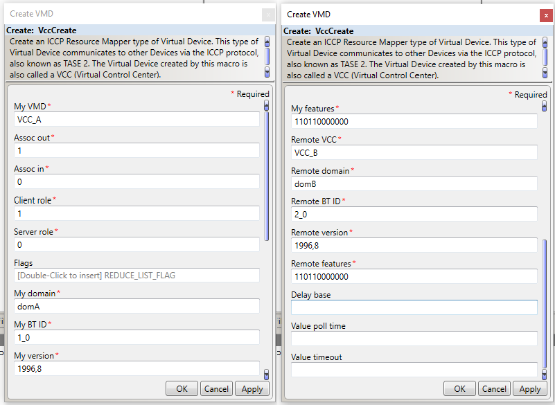
- Specify the name of the VCC in the My VMD field as VCC_A.
- Set Assoc in to 0 and Assoc out to 1. This means the local VCC (VCC_A) will attempts to make an outbound ICCP association with its remote peer (as opposed to listening for an inbound association).
- Set Client role to 1.
- Set Server role to 0. In this example, the local VCC is just an ICCP client.
Note: A VCC can serve as an ICCP client and an ICCP Server ( a dual-role VCC) simultaneously. A single VCC can also make associations with more than one other VCC. But for every role a VCC plays, it needs a dedicated association.
- In the Flags field, set the REDUCE_LIST_FLAG. This flag lets the LEC Server adjust which points it includes in its transfer set requests if one or more of those points do not exist on the remote ICCP server.

Note: The string that populates the Flags field is determined by which flags are Set or Unset. A blank field uses the default setting for all flags. A flag that is explicitly set appears in this field as its name. A flag that is explicitly unset appears as its name with a minus sign (‘-‘), in front of it. Explicitly set or unset flag instructions are concatenated together with the pipe character (‘|’). In this tutorial, this field appears as REDUCE_LIST_FLAG but another entry for this field might look something like RELAY_FLAG|INFO_FLAG|-EXCLUDE_FLAG.
- Specify the domain of the server in the My domain as domA.
- Type 1_0 in the My BT ID field. This field specifies the local VCC’s bilateral table ID.
- Type 1996,8 in the My version field.
- In the My features field, type the 12-bit string, 110110000000. In this example, the local VCC supports ICCP Blocks 1, 2, 4, and 5.
Note: While establishing an ICCP association, the client accesses a standard ICCP object called Supported_Features. This object is represented as a bit-string that specifies the ICCP Conformance Blocks supported in the server. To learn more about ICCP conformance blocks, see ICCP Reference.
- Type VCC_B in the Remote VCC field.
- In the Remote domain field, type domB.
- In the Remote BT ID field, type 2_0.
- Type 1996,8 in the Remote version field.
- In the Remote features field, type 110110000000.
- Leave the Delay base, Value poll time, and Value timeout fields blank.
See the following image for a summary of what the fields in VccCreate tool should look like.
- Click OK to create this VMD.
Specify the ICCP Association Parameters for the Local VCC
- In the Configuration Manager, select the local VCC in the Node Table by clicking where it says VCC_A.
- Then open the VMD tab of the Properties panel.
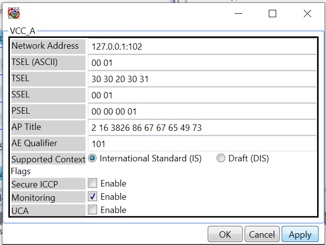
- In the VMD tab of the Properties panel, click My VMD. A window that lets you specify the network connection and ICCP association parameters for VCC_A will appear :
Note: To fill in the information in this window, we will refer to the table of ICCP Association information that was included at the beginning of this section. To find out more about the meaning of each of these parameters, see ICCP Node Templates in LCM.
- Set the Network Address field to 127.0.0.1:102.
- Set the TSEL (ASCII) field to 00 01. This will cause the TSEL field to update to 30 30 20 30 31.
- Set the SSEL field to 00 01.
- Set the PSEL field to 00 00 00 01.
- Set the AP Title field to 2 16 3826 86 67 67 65 49 73.
- Set the AE Qualifier field to 101.
- Leave the Supported Context, Secure ICCP, Monitoring, and UCA fields as their default values.
- Click Apply.
Specify the ICCP Association Parameters for the Remote VCC
- In the Configuration Manager, select the local VCC in the Node Table by clicking where it says VCC_A.
- Then open the VMD tab of the Properties panel.
- In the VMD tab of the Properties panel, click Remote VCC. A window that lets you specify the network connection and ICCP association parameters for VCC_B will appear :
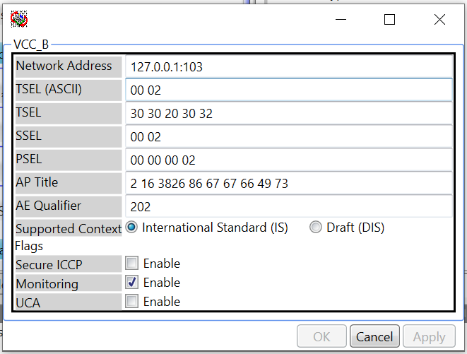
- Set the Network Address field to 127.0.0.1:103.
- Set the TSEL (ASCII) field to 00 02. This will cause the TSEL field to update to 30 30 20 30 32.
- Set the SSEL field to 00 02.
- Set the PSEL field to 00 00 00 02.
- Set the AP Title field to 2 16 3826 86 67 67 66 49 73.
- Set the AE Qualifier field to 202.
- Leave the Supported Context, Secure ICCP, Monitoring, and UCA fields as their default values.
- Click Apply.
Step 4: Create a Script VMD
A Script VMD represents an interface to a Python script running in LEC’s embedded real-time Python interpreter. You can create your own scripts or use one of the many scripts that ship with the LEC installer.
In this tutorial, your Script VMD will be an interface to a Python script called PointLogger.py. This script is part of your LEC installation and is located in the C:\ProgramData\LiveEnergyConnect\Scripts directory. This Script VMD will get point values from the Processor write the values of the points to a specified log file as they come in.
Note: Although, this particular script’s functionality is quite simple, Script VMD’s provide the ability to perform complex filtering. They can be used to quickly create interfaces to non-standard, external applications.
Create the configurations script VMD
- Navigate to the Templates panel and select the VMD tab.
- Select the ScriptCreate template which will launch the ScriptCreate tool.
- Enter Logger in the My VMD field.
- In the Flags field, specify ICCP_FLAG. This allows the Script VMD to know about the standard ICCP datatypes.
- Leave the Script file field blank.
Note: The Script file field is not where you specify the script associated with a Script VMD. This field instead allows you to specify another script that controls (enables or disables) this Script VMD. The script that Script VMD uses is specified later with a SetupScript node within the Script VMD.
- Leave the UseCommonThread, Python instance, and Computer ID fields blank.
- Click OK.
Step 5: Arrange the VMD’s in the Node Monitor
Before creating the nodes within each VMD and connectors between those nodes, it is helpful to arrange the VMD’s in the Configuration Manager so that arrangement is representative of the dataflow we are creating. Typically, in engineering diagrams, data flows from left (input) to right (output).
Arrange the VMDs
- Right-click the Processor VMD right where it says Processor.
- Select VCC_A and drag it to place between CFG_LDSMGR and Processor VMD’s.
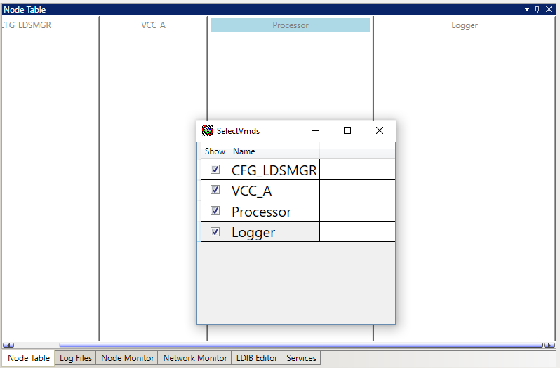
- This updates the order in which the VMD’s are displayed in the Node Table.
Note: To hide a VMD, select the checkbox next to the name of the VMD to hide. The order of the VMD’s only affects the order in which they are displayed in RCM’s Node Table. It does not affect the dataflow at all.
- Save the configuration. Select File then select Save Configuration.
- After creating all the required VMD’s, the next step is to create the nodes inside those VMD’s.
Step 6: Create Nodes in the VCC
Points coming from the remote ICCP server enter the local VCC (VCC_A) as input nodes with the type PointFromIccp. This sample configuration uses a batch file to specify these input nodes. You will need to create one prototype node that is used (along with the batch file) to generate all of the PointFromIccp nodes in the local VCC.
There are also a couple of setup nodes that are needed in the VCC_A VMD: two nodes to control the ICCP association and two nodes to control and define a Data Set Transfer Set.
Create the PointFromIccp Prototype Node
- Select the VMD called VCC_A.
- Navigate to the Input tab of the Templates panel. The list of possible input node templates used with the type of selected VMD is displayed.
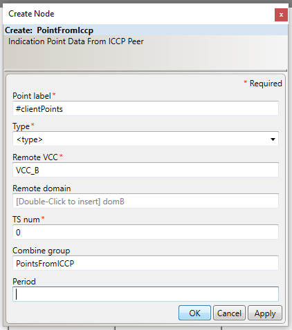
- Select PointFromIccp from the list of node templates.
- In the Point label field, type #clientPoints.
Note: A point label that contains a string starting with the pound character (‘#’) signifies that the node is a prototype node. In one of the configuration’s batch files there will be a table that contains a column ( called the driven column) which matches the string starting with the pound character (‘#’).
- In the Type field, enter <type>.
- In the Remote VCC field, enter VCC_B.
- Leave the Remote domain field blank.
- In the TS num field, enter 0. This will make the ICCP client (VCC_A) ask the remote ICCP server to organize the points it cares about into the Data Set Transfer Set called TransferSet_0.
- In the Combine group field, enter PointsFromICCP.
- Select OK.
VCC_A acts as an ICCP client so it makes an outbound ICCP association. A VccAssocOutControl setup node and a related Constant input node is used to specify this outbound association. The Constant node is used to specify an initial value for the VccAssocOutControl node at start-up.
Create the VccAssocOutControl Node
- With VCC_A still selected, navigate to the Setup tab of the Templates panel.
- In the Point label field, enter the node name assocOutCtrl.
- In the Remote Vcc field, enter VCC_B.
- In the Init state var field, type assocOutCtrl_init. This is the node label that will be used for the Constant node that defines the initial state of this VccAssocOutControl node. This field needs to match the node label of the Constant node exactly.
- Leave the Association flags and Stale time fields blank.
- In the Combine group field, enter AssociationControl.
- Click OK.
Note: The Combine group field is used to organize different nodes into groups. Nodes with the same value for the Combine group field will be displayed together underneath a combine group label in the Node Table and Node Monitor tabs.
Create the Constant Node that Will Initialize the Value of the VccAssocOutControl Node
- With the VCC_A still selected, navigate to Input tab of the Templates panel. This will list all possible types of input nodes that can be used with the type of the selected VMD.
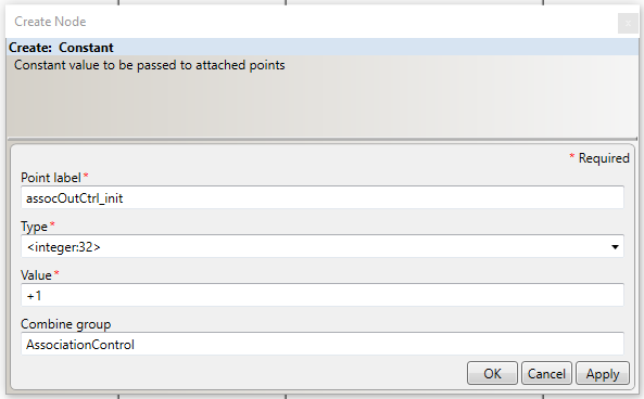
- Select the Constant option from the list of node templates in the Input tab.
- In the Point label field, enter the node name assocOutCtrl_init.
Note: Two (non-prototype) nodes that live in the same VMD and the same point domain within that VMD cannot have the same point label. However, one of these (non-prototype) nodes point labels can contain a substring that is another node’s entire point label.
- In the Type field enter <integer:32> which in the LEC Server’s syntax for MMS, defines a 32-bit integer.
- In the Value field enter +1. This will be the initial value that the node assocOutCtrl uses at start- up.
Note: In the LEC Server, an ICCP association variable can be in one of 3 states represented by an integer value: disabled (+0), enabled (+1), or associated (+2).
- In the Combine group field enter AssociationControl.
- Click OK.
Note: The Configuration Manager automatically creates an Implicit Edge connector from the Constant node created in the last step to the node called assocOutCtrl which references this Constant node.
VCC_A will act as an ICCP client. When ICCP Block 2 is supported by both ICCP peers, an ICCP client can define Data Set Transfer Sets. These Data Set Transfer Sets tell the server which points the client wants to get information about and how it wants that information delivered.
Note: Data Set Transfer Sets are a type of ICCP object.
To configure a Data Set Transfer Set in the LEC Configuration Manager, we will use a VccTransferControl setup node, a related Constant input node, and a DsTansferSet setup node.
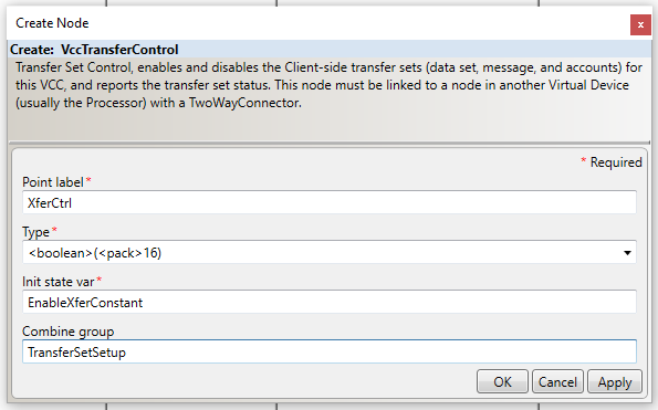
Create the VccTransferControl Node
- With the VCC_A still selected, open the Setup tab in the Templates Panel.
- Select VccTransferControl from the list of node templates in the Setup tab.
- In the Point label field, enter the node name XferCtrl.
- In the Type field, enter <boolean>(<pack>16), which in the LEC Server’s syntax for MMS defines a structure made up of 16 bits.
- In the Init state var field, enter EnableXferConstant. This will be the node label used for the Constant node that defines the initial state of this VccTransferControl node. Again, this field needs to match the node label of the related Constant node exactly.
- In the Combine group field TransferSetSetup.
- Click OK.
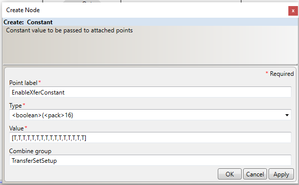
Create the Constant Node That Will Initialize the Value of the VccTransferControl Node
- With VCC_A still selected, open the Input tab in the Templates Panel.
- Select the Constant option from the list of node templates in the Input tab.
- In the Point label field enter the node name EnableXferConstant.
- In the Type field, enter <boolean>(<pack>16).
- In the Value field, enter [T,T,T,T,T,T,T,T,T,T,T,T,T,T,T,T]. This will be the initial value that the node called XferCtrl uses at start-up.
Note: By making all 16 bits of the VccTransferControl node have a value of True, you are enabling VCC_A to define up to 16 Data Set Transfer Sets. After a node with the type <boolean>(<pack>n) has been created, you can enable or disable a particular bit by clicking the text entry area for Value field. A pop-up with radio buttons for each bit will appear and allow to select which bits in the object should be set to True and False.
- In the Combine group field, enter TransferSetSetup.
- Click OK.
Create the DsTransferSet Node
- With the VCC_A still selected, open the Setup tab in the Templates Panel.
- Select DsTransferSet from the list of node templates in the Setup tab.
- In the TS num field, enter the node name 0 so that the whole node label will be TransferSet_0.
- In the Remote domain field, enter domB.
- In the Remote VCC field, enter VCC_B.
- Leave the Start time and Start delay fields blank.
- In the IntervalCheck field, enter 3.
- Leave the Start time and Start delay fields blank.
- In the IntegrityCheck field, enter 0.
- In the IntervalTimeOut field, enter 0.
- In the IntegrityTimeOut field, enter 1.
- In the ObjectChange field, enter 1.
- In the OperatorRequest field, enter 1.
- In the RBE field, enter 1.
- Leave the IntervalDelay, AllChangesReported, Critical, CircumventSiemansBug, and Do read fields blank.
Note: For more information about each field in the DsTransferSet node template, see ICCP Reference.
- In the Combine group field, enter TransferSetSetup.
- Click OK.
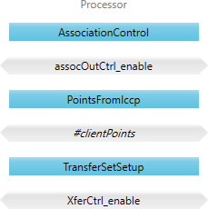
At this point in the tutorial, there should be five different nodes in VCC_A.
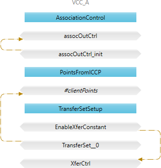
Notice that the nodes are organized into three different combine groups each with its own label: AssociationControl, PointsFromICCP, and TransferSetSetup. Also, notice that the Configuration Manager has automatically built three implicit edge connectors (brown arrows) because of the relationships that were defined between some of the nodes.
Step 7: Create Nodes in the Processor VMD
Any VMD in an LEC Server configuration can communicate with any other VMD in the configuration using a Processor VMD as a proxy. A Processor VMD will also typically contain nodes used for filtering data or for monitoring and controlling associations.
The IntermediatePointMonitor node is one of the most used types of nodes in a Processor VMD. Although it is a filter node, the IntermediatePointMonitor node is used to read (and write) the value of a point at a particular step in its dataflow through the LEC server.
In this example ICCP client configuration, you will create IntermediatePointMonitor nodes and use them to get the data received by the VCC_A VMD into the Processor VMD.
You will also create IntermediatePointMonitor nodes to allow the Configuration Manager and the LEC Server to read and write to the nodes in the VCC_A that are control the outbound association and Data Set Transfer Set control.
Create Three IntermediatePointMonitor Nodes in the Processor VMD
- Select the VMD Processor.
- Open the Filter tab in the Templates panel.
- Select IntermediatePointMonitor from the list of node templates in the Filter tab.
- In the Point label field, enter the node name #clientPoints.
- In the Type field, type <type>.
- Leave the Light field blank.
- In the Combine group field, enter PointsFromIccp.
- Select OK.
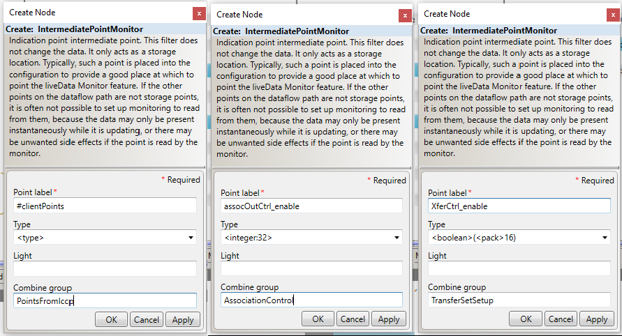
- Repeat steps 1 -8 to create two more IntermediatPointMonitor nodes in the Processor VMD: one called assocOutCtrl_enable and one called XferCtrl_enable. The values for all three IntermediatePointMonitor nodes int the VMD are specified in the table below.
| Template Node Field | #clientPoints | assocOutCtrl_enable | XferCtrl_enable |
|---|---|---|---|
|
Point label |
#clientPoints |
assocOutCtrl_enable |
XferCtrl_enable |
|
Type |
<type> |
<integer:32> |
<Boolean>(<pack>16) |
|
Combine Group |
PointsFromIccp |
AssociationControl |
TransferSetSetup |
- While creating each node, check that each matches the relevant template node in the figure below to ensure that there are no typos.
These IntermediatePointMonitor nodes are the only nodes that need to be created in the Processor VMD. At this point in the tutorial, there should be three different nodes in the Processor VMD as is shown in the figure below.
Step 8: Create Nodes in the Script VMD
The Script VMD called Logger will need a setup node and an output node. The setup node, a SetupScript node, will specify information about which Python script to use in the VMD. The output node, a PointToScript node will define the output behavior of the Script VMD based on the methods in the Python script. In this example, the output behavior of the Logger Script VMD will be to write changes in value to a CSV file.
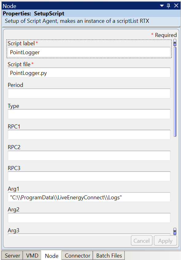
Create a SetupScript Node in the Logger Script VMD
- Navigate to Setup tab of the Templates panel.
- Select the SetupScript template to display the Create Node form.
- Enter PointLogger in the Script label field.
- Enter PointLogger.py in the Script file field.
- Enter C:\\ProgramData\\LiveEnergyConnect\\Logs in the Arg1 field. Make sure the file path is in double quotes and contains double backslashes.
- Type Setup in the Combine Group field.
- Click OK.
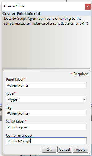
Create a PointToScript Node in the Logger Script VMD
- Navigate to Output tab of the Templates panel.
- Select PointToScript from the list of templates.
- Type #clientPoints in the Point label field.
- Type <type> in the Type field.
- Type #clientPoints in the Tag field.
- Type PointLogger in the Script label field.
- Leave the Python instance field blank, and type PointsToScript in the Combine group field.
- Click OK to finish this step.
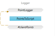
These two nodes are the only nodes you need to create in the Script VMD. At this point in the tutorial, there should be two different nodes in the Script VMD called Logger as shown below.
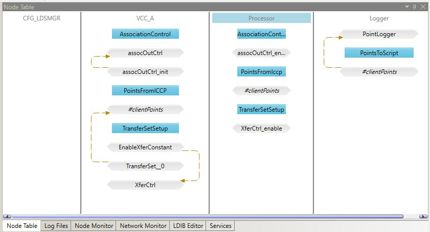
All nodes for our example LEC Server configuration have been created. If everything was specified correctly, the view of the configuration from the Node Table tab of the Central panel should look like the one shown in the figure below.
The last step in building the configuration is to connect the nodes.
Step 9: Connect the Nodes
This LEC Server configuration requires Update connectors and Two Way connectors between some of the nodes.
Create Connectors Between Nodes in the Configuration
- Click the Create Update Connector icon (the blue arrow) from the menu.
- The Create Connector tool window will open.
- Type VCC_A in the Src VMD field.
- Type #clientPoints in the Source label field.
- Type Processor in the Dest VMD field.
- Type #clientPoints in the Dest label field.
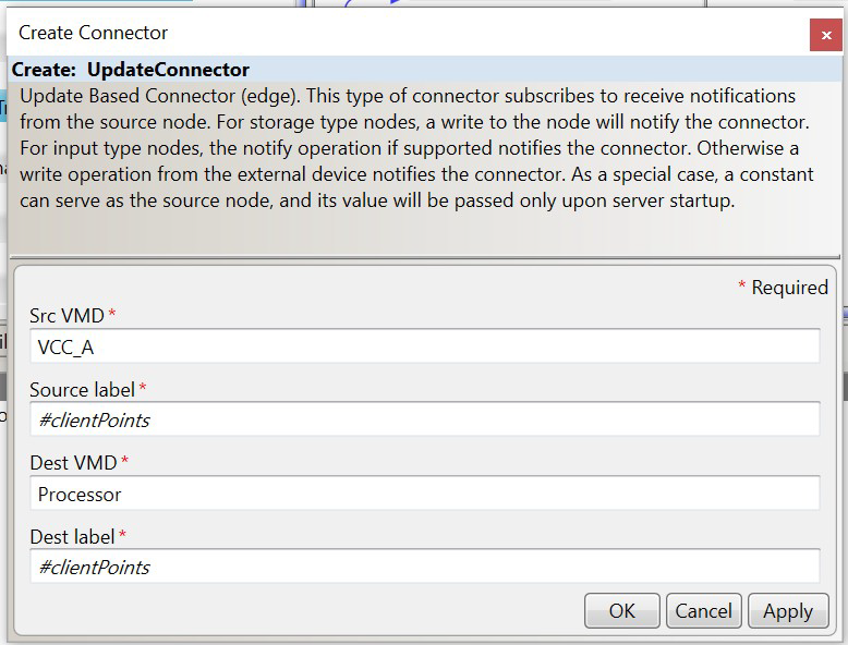
- Click OK.
- Use the Create Connector tool and the values in the following below to create the remaining three connectors in this example server configuration.
The following table shows the values used to create each Update Connector and Two-way Connector in this example server configuration.
| Connector Type | Source VMD | Source Node | Destination VMD | Destination Node |
|---|---|---|---|---|
|
Update Connector |
VCC_A |
#clientPoints |
Processor |
#clientPoints |
|
Update Connector |
Processor |
#clientPoints |
Logger |
#clientPoints |
|
Two-Way Connector |
VCC_A |
XferCtrl |
Processor |
XferCtrl_enable |
|
Two-Way Connector |
VCC_A |
assocOutCtrl |
Processor |
assocOutCtrl_enable |
Once all four of these connectors have been created, the view of your LEC Server configuration from the Node Table tab should look like the one shown in the figure below.

Step 10: Validate the Configuration
Now that the example configuration is completed, let’s validate that it works just like the provided example configuration.
Load the Batch File
- Navigate to the Batch Files tab of the Properties panel and select Load Share.
- When prompted select the example batch file called IccpPoints.csv from the C:\ProgramData\LiveEnergyConnect\Config directory.
- Confirm that the prototype nodes in the configuration generate the nodes defined in the batch file as expected.
Note: If loading the batch file doesn’t generate any nodes or if you receive an error message from the Configuration Manager, one or more field values in the relevant prototype node does not match the column values in the batch file.
Start the LEC Server as a Server Process
- Confirm that the Soap port and Mms port are specified as 8089 and 103 respectively in the Server tab of the Properties panel. If not, specify the field values and click Apply.
- Click the Start Server Process button in the Configuration Alias panel.
- Confirm that the server starts by looking at the Running Status in the Configuration Alias panel.
- Confirm that the server is attempting to make an outbound ICCP association with the remote ICCP server by looking at the Network Monitor tab of the Central pane. The association between VCC_A and VCC_B should have a status that reads Attempting.
If you are working through this tutorial you should have already created the configuration alias called ScadaSim from the earlier tutorial section of the guide called A Quick Configuration Manager Tutorial.
If you skipped that section or if you just no longer have the example server configuration loaded for the ScadaSim configuration alias, then refer to that tutorial to prepare the SCADA server simulator configuration.
Test Against the Simulated SCADA Server Example Configuration
- Switch to the Configuration Alias ScadaSim using the drop-down selector in the Configuration Alias panel.
- Confirm that the IccpSimPoints.csv batch file is loaded by looking at the Batch Files tab in the Properties panel. If it is not loaded, then load it is using Load Share.
- Click Start Server Process in the Configuration Alias panel.
- Confirm that the server starts by looking at the Running Status in the Configuration Alias panel.
- Confirm that the two running server instances establish an ICCP association using the Network Monitor tab of the Central pane. The association between VCC_A and VCC_B should have a status that reads Connected.
- Switch back to the configuration alias cfg.
- Confirm that point values are being updated in the Processor VMD of this server instance. You can verify this using the Node Monitor tab in the Central pane.
- Finally, confirm that the embedded Python script used in the Logger VMD is logging point values in CSV file in the specified directory (specified in the Arg1 field of the VMD’s SetupScript node).
- Save the configuration. Click Save As from the File menu.
You have now successfully created your first LEC Server configuration from scratch.
If you are having trouble validating this LEC Server configuration, try the following:
- Confirm there are no missing nodes or connectors.
- Confirm there are no typos in the values used for the various parameters of the VMD’s, nodes, and connectors.
- Confirm there are not two running instances of the server configured to use the same ports for SOAP and MMS communication.
- Confirm that you are not running two instances of LEC Configuration Manager simultaneously.
For any further issues, contact My Oracle Support.