NAT on DRG - Part 4 - Shared services VCN
Introduction
A shared services VCN is a very common design in Oracle Cloud Infrastructure (OCI). One central VCN hosts the services everybody needs, such as DNS, monitoring, backup, a jump host or a licence server, and many other VCNs consume those services through a Dynamic Routing Gateway (DRG).
The design works well until two consumers use the same IP range. A service provider that connects customers to a shared platform runs into this almost immediately, because the provider does not control the addressing of its customers. The same happens inside a large organisation where business units built their VCNs independently. When two consumers both use 10.0.1.0/24, the shared services VCN cannot send a reply back: the address 10.0.1.13 could be in either VCN.
NAT on DRG solves this on the DRG itself. Each consumer VCN gets a DRG NAT policy on its attachment that translates its source addresses to a unique “shadow” CIDR. The shared services VCN only ever sees the shadow CIDRs, so every consumer is unique from its point of view.
| VCN | Role | Real subnet CIDR | CIDR seen by the shared services VCN |
|---|---|---|---|
uc4-vcn-c1 |
Customer 1 | 10.0.1.0/24 |
192.168.10.0/24 |
uc4-vcn-c2 |
Customer 2 | 10.0.1.0/24 |
192.168.20.0/24 |
uc4-vcn-shared |
Shared services | 10.50.1.0/24 |
Not translated |
Compared to the earlier parts of this series there are two differences worth pointing out:
- Only the source is translated. The shared services VCN has a unique CIDR (
10.50.0.0/16), so the customers can use its real addresses. The NAT rules are source NAT (SNAT) only. - Only the customer attachments have a policy. The attachment of the shared services VCN has no NAT policy at all.
[!NOTE] A NAT rule describes traffic entering the DRG through the attachment that holds the policy. For traffic in the opposite direction, leaving the DRG through that same attachment, the DRG applies the reverse translation automatically. You do not create a second rule for the return path.
Other Use Cases
This tutorial is part of a series of five. Every part solves a different overlap scenario with the same building blocks.
- Part 1: NAT on DRG - Part 1 - Overlapping CIDRs between two local VCNs
- Part 2: NAT on DRG - Part 2 - Overlapping CIDRs between multiple remote VCNs
- Part 3: NAT on DRG - Part 3 - Overlapping CIDRs between OCI and On-Premises
- Part 4 (this tutorial): NAT on DRG - Part 4 - Shared services VCN
- Part 5: NAT on DRG - Part 5 - Overlapping CIDRs between OCI and On-Premises with BGP
Diagram
Multiple VCNs must access a common shared service, with potential overlap between organizations
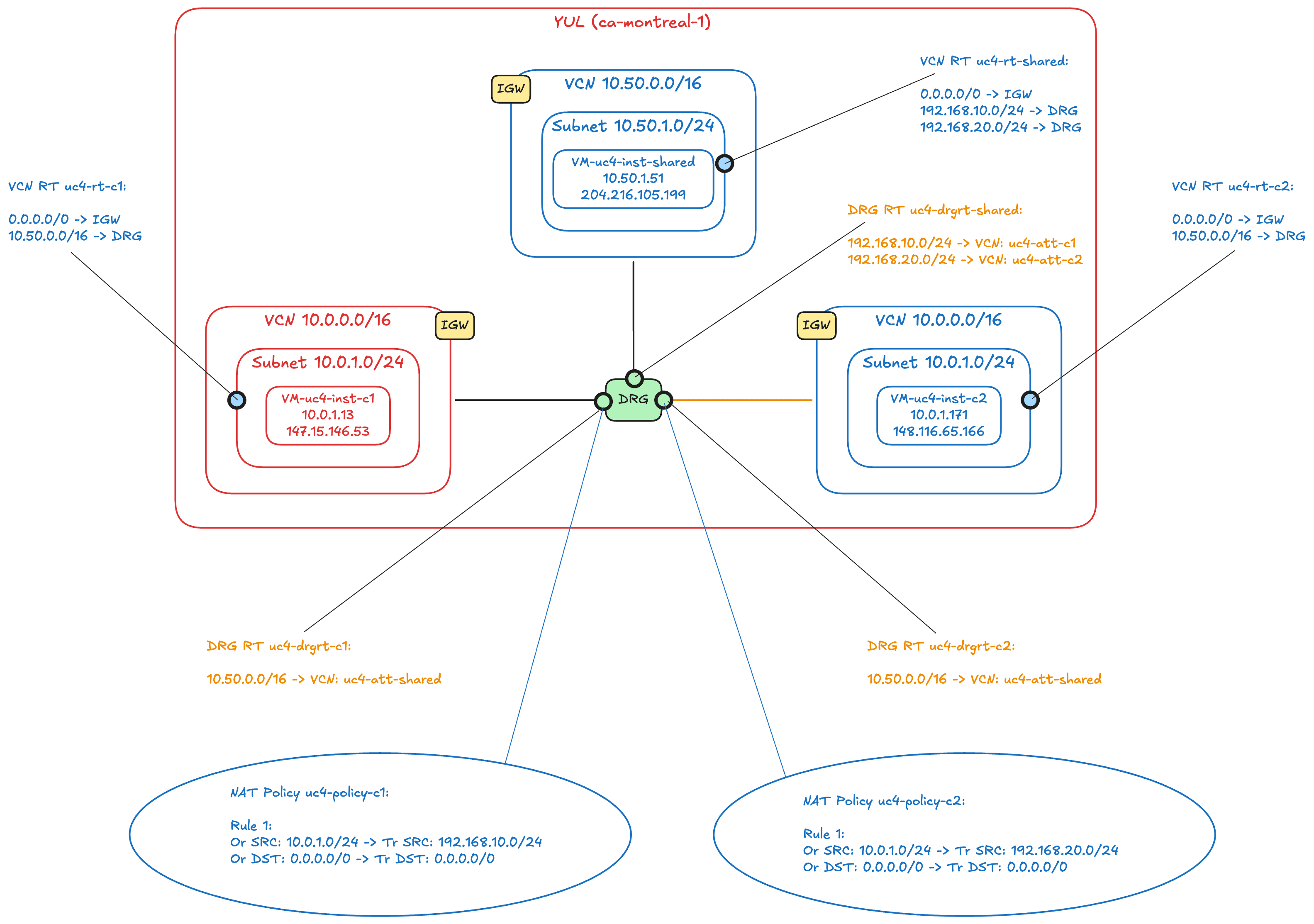
The diagram shows every object you configure in this tutorial:
- Three VCNs in the Canada Southeast (Montreal) region. The two customer VCNs both use
10.0.0.0/16with a subnet10.0.1.0/24. The shared services VCN uses10.50.0.0/16with a subnet10.50.1.0/24. Each VCN has one test instance. - One DRG with three VCN attachments:
uc4-att-c1,uc4-att-c2anduc4-att-shared. - Three VCN route tables (blue text). The customers route
10.50.0.0/16to the DRG. The shared services VCN routes both shadow CIDRs to the DRG. - Three DRG route tables (orange text), one per attachment. The customer tables only know the way to the shared services VCN. The shared table knows the way to each shadow CIDR.
- Two DRG NAT policies (the ellipses), one per customer attachment, each with a single source NAT rule.
Prerequisites
- An OCI tenancy and a compartment in which you are allowed to manage networking resources (VCNs, DRGs, DRG attachments, DRG route tables and DRG NAT policies) and compute instances.
- Three VCNs that already exist. This tutorial does not create them. In the lab they are
uc4-vcn-c1anduc4-vcn-c2, both10.0.0.0/16with a subnet10.0.1.0/24, anduc4-vcn-shared,10.50.0.0/16with a subnet10.50.1.0/24. Each VCN has an internet gateway and a route table that is assigned to the subnet and sends0.0.0.0/0to the internet gateway. Steps 01 to 03 walk through this starting point. - A DRG that supports NAT. NAT on DRG is not available on legacy (V1) DRGs, and not on DRGs that have disintermediation, high-throughput mode or route unification enabled. A newly created DRG works.
- Three compute instances to test with, one in each VCN. In this tutorial they are called
uc4-inst-c1(10.0.1.13),uc4-inst-c2(10.0.1.171) anduc4-inst-shared(10.50.1.51). Each has a public IP address so you can reach it with SSH. - An SSH key pair for the instances, and the public IP address you connect from (to allow it in the security lists).
- Basic knowledge of VCN route tables and DRG route tables. If NAT on DRG is new to you, start with NAT on DRG - Part 1 - Overlapping CIDRs between two local VCNs.
[!NOTE] The names, CIDRs and IP addresses in this tutorial come from the lab in the screenshots. You can use your own, as long as the shadow CIDRs do not overlap with anything else in your network and have the same prefix length as the CIDR they replace.
Steps
- STEP 01: Review the three VCNs
- STEP 02: Review the subnets
- STEP 03: Review the internet gateways
- STEP 04: Configure the security lists
- STEP 05: Create the DRG and attach the three VCNs
- STEP 06: Create a DRG route table for each attachment
- STEP 07: Configure the VCN route tables
- STEP 08: Create the DRG NAT policies and rules
- STEP 09: Associate the NAT policies with the customer attachments
- STEP 10: Test the connectivity
Step 01: Review the three VCNs
We start with the three VCNs. Two of them belong to customers who picked the same address space, and the third one hosts the shared services with a range that nobody else uses.
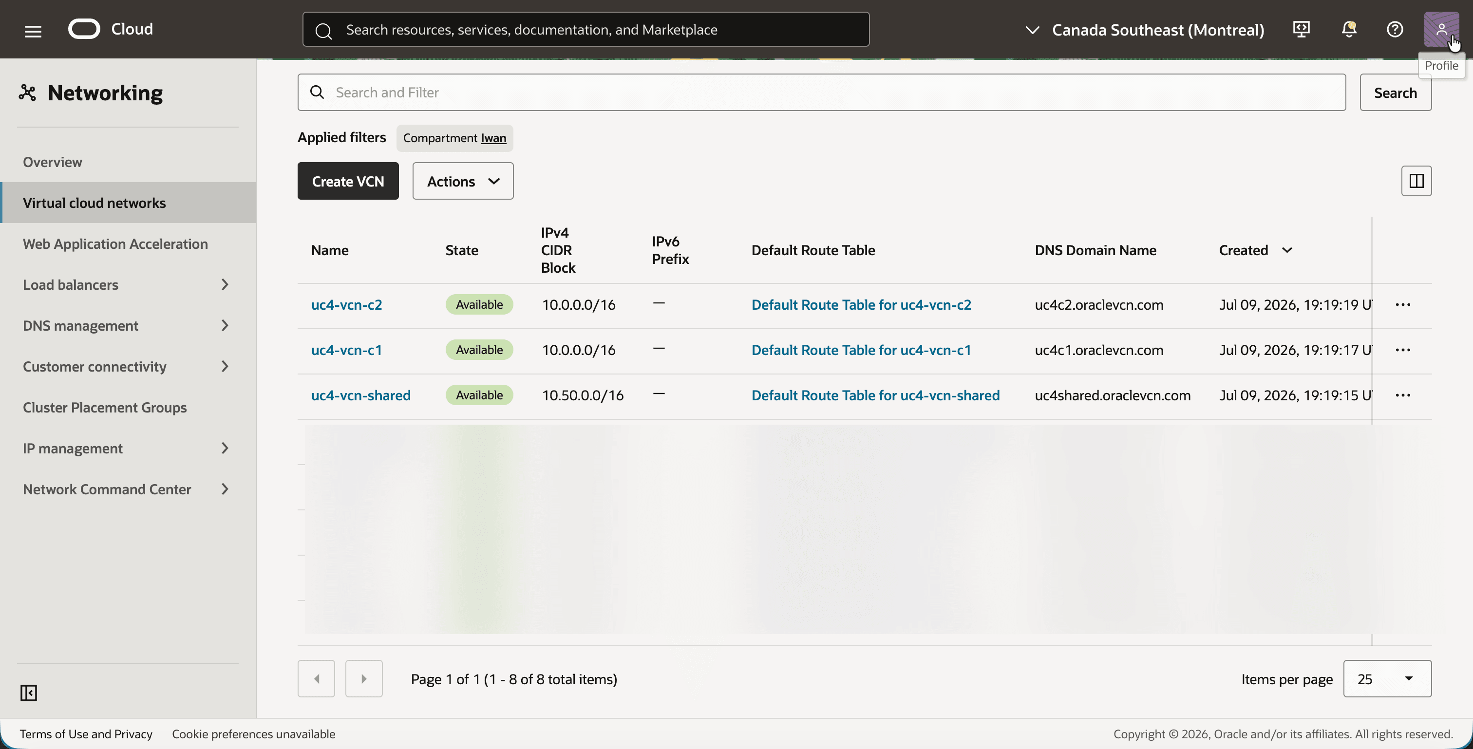
- Open the navigation menu, click on Networking and then on Virtual cloud networks.
- Notice the three VCNs.
uc4-vcn-c1anduc4-vcn-c2both have the IPv4 CIDR Block10.0.0.0/16, anduc4-vcn-sharedhas10.50.0.0/16.
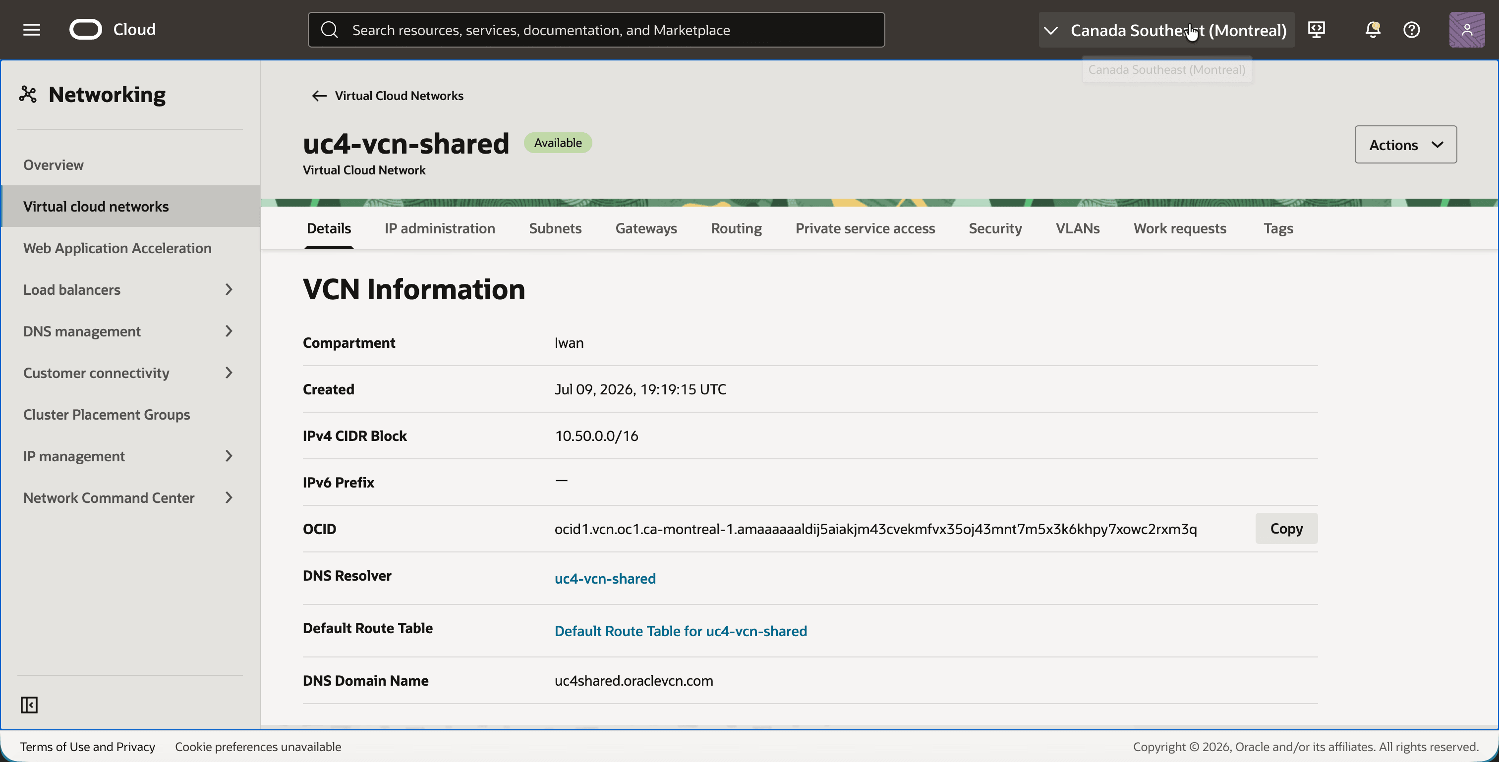
- Click on
uc4-vcn-shared. - Notice the IPv4 CIDR Block
10.50.0.0/16on the Details tab.
- Go back and click on
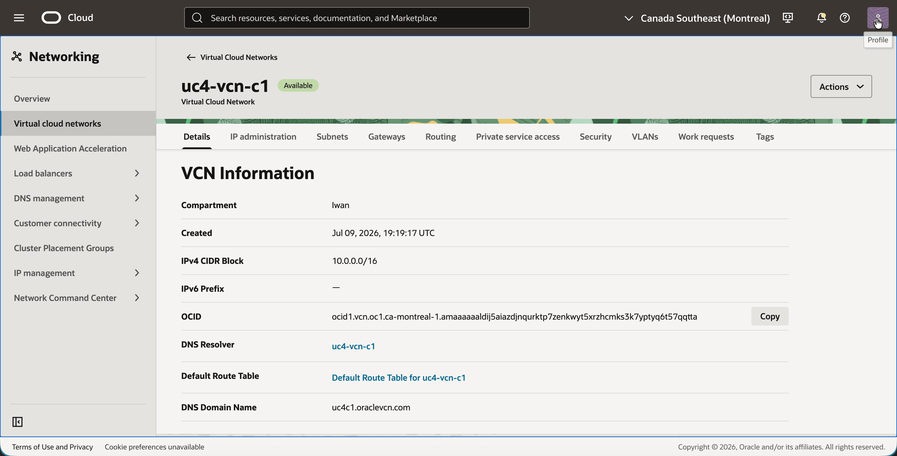
uc4-vcn-c1. - Notice the IPv4 CIDR Block
10.0.0.0/16.
- Go back and click on
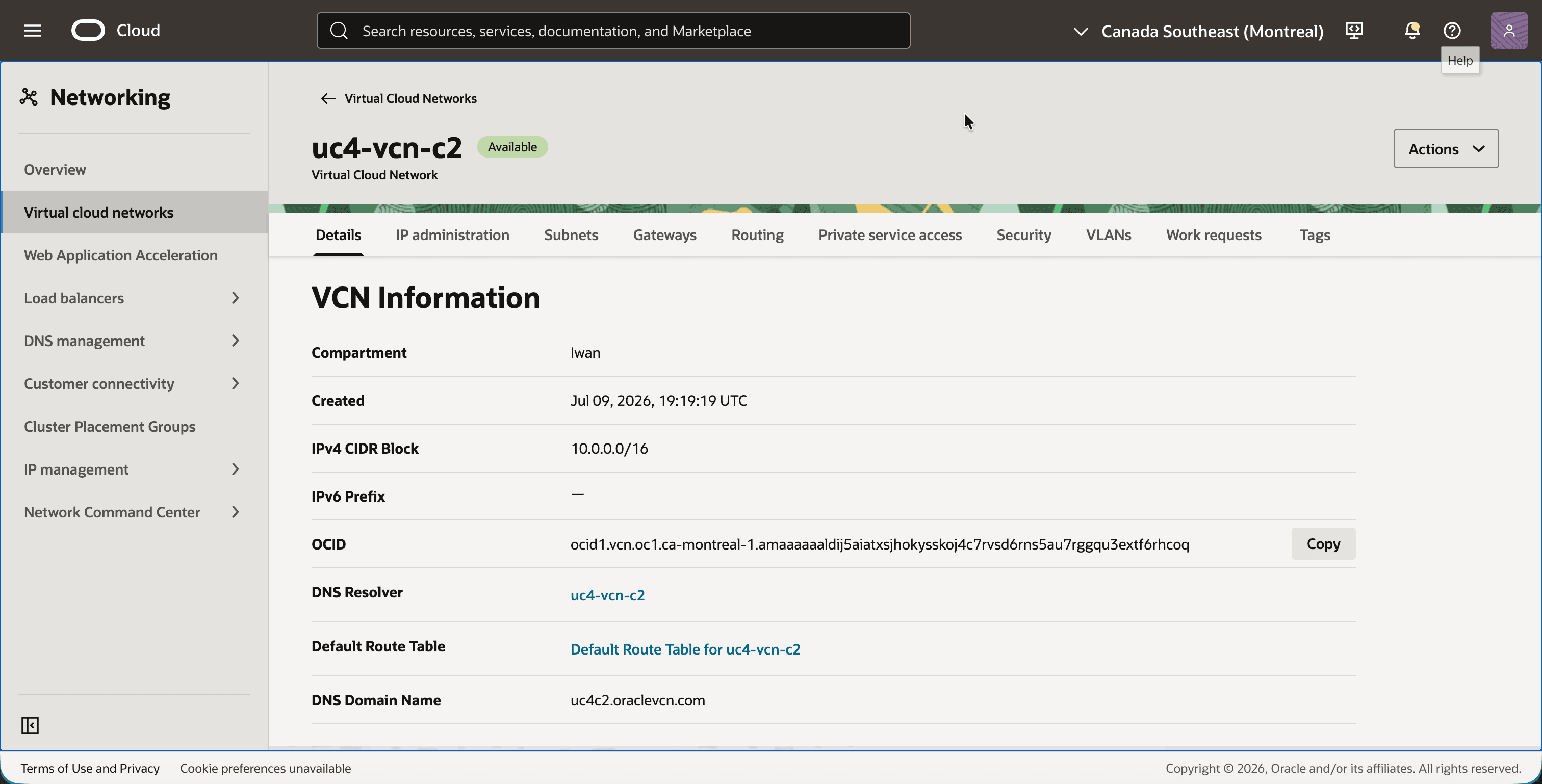
uc4-vcn-c2. - Notice that this VCN has the same IPv4 CIDR Block
10.0.0.0/16asuc4-vcn-c1.
Step 02: Review the subnets
Both customer VCNs have a single public subnet with the CIDR 10.0.1.0/24. This is the range that the NAT rules translate later. The shared services VCN has one subnet, 10.50.1.0/24, which is not translated.
- In
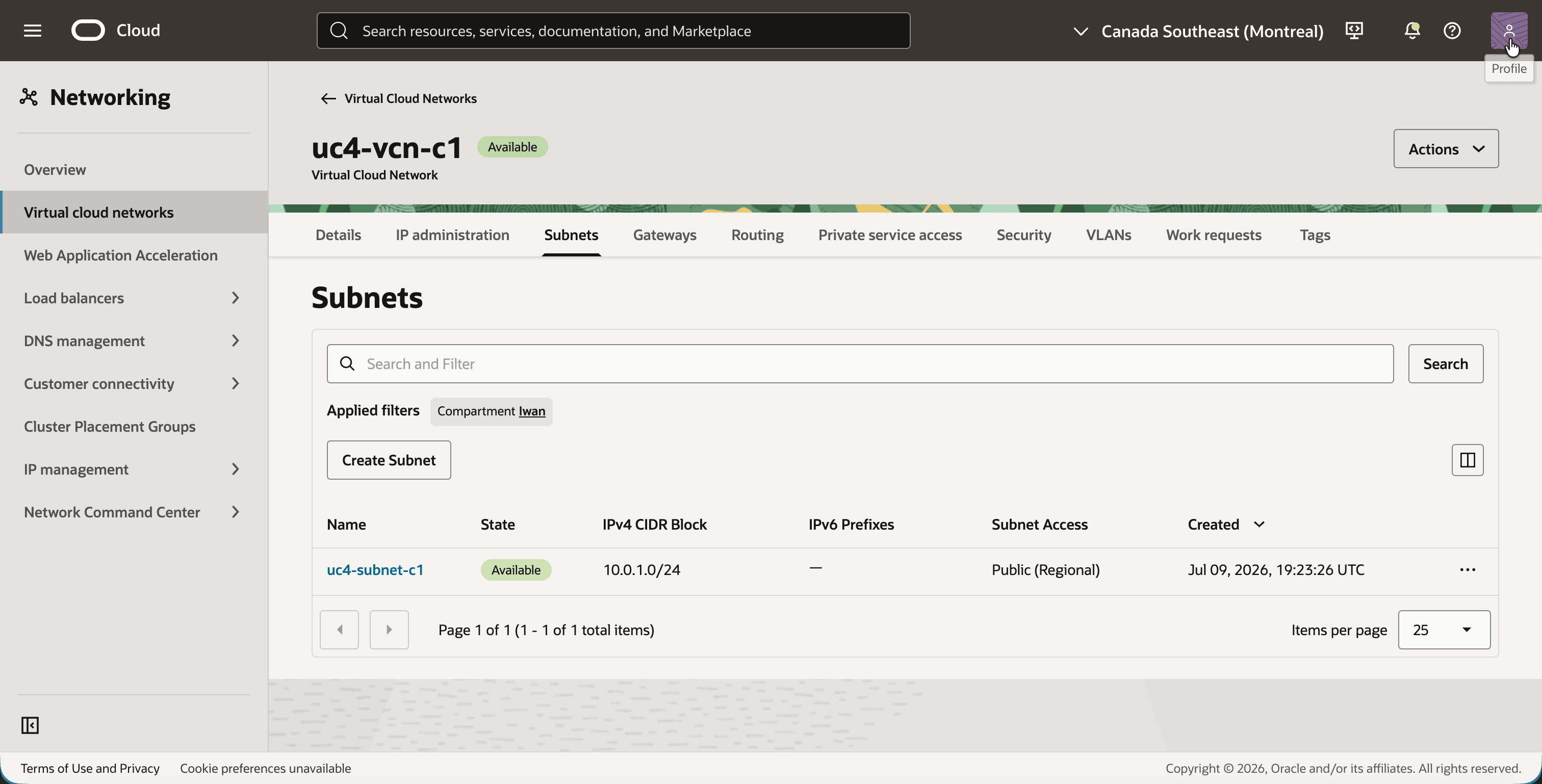
uc4-vcn-c1, click on the Subnets tab. - Notice the subnet
uc4-subnet-c1with the IPv4 CIDR Block10.0.1.0/24.
- In
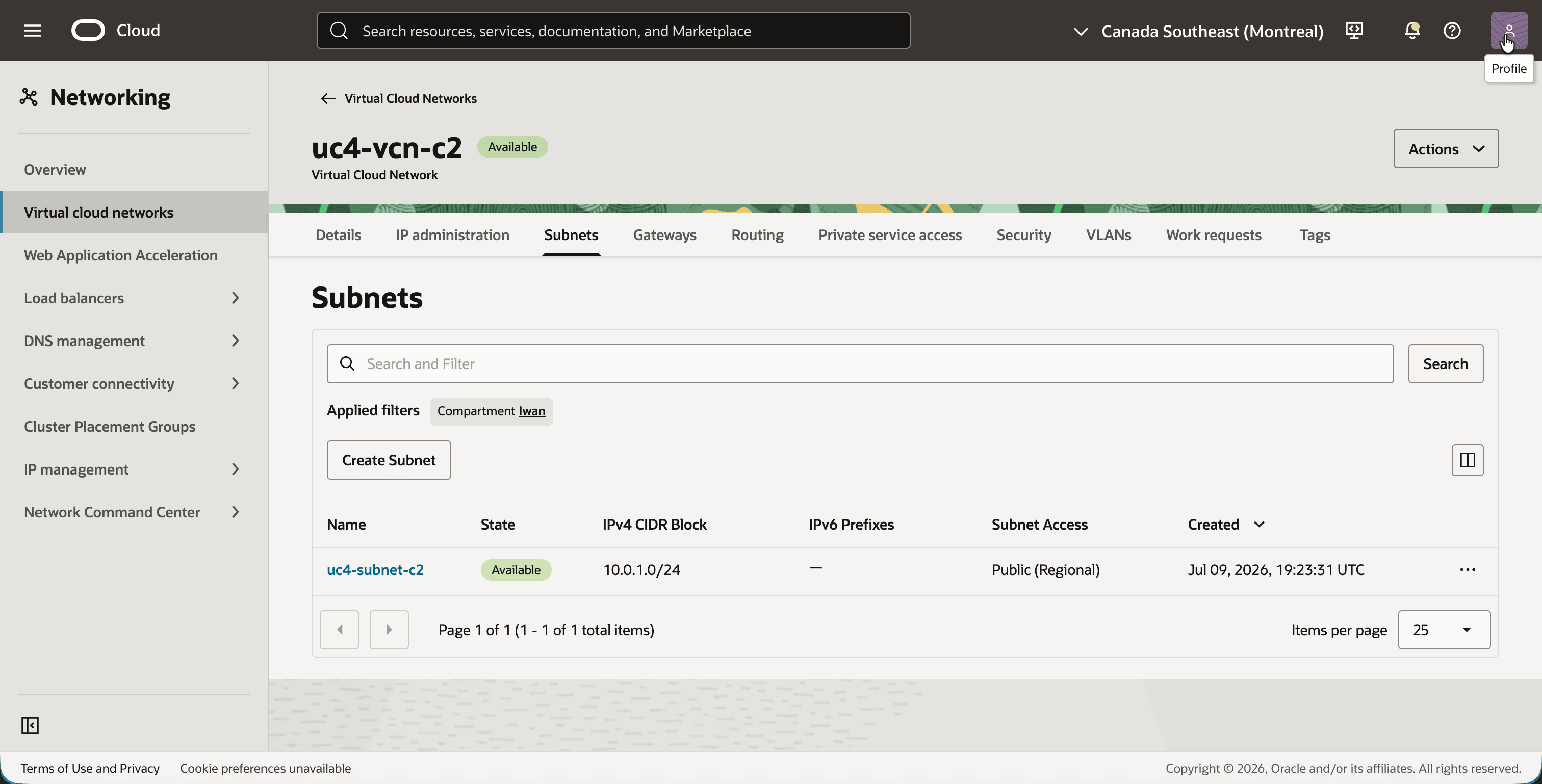
uc4-vcn-c2, click on the Subnets tab. - Notice the subnet
uc4-subnet-c2with the same IPv4 CIDR Block10.0.1.0/24.
Step 03: Review the internet gateways
The internet gateways have nothing to do with NAT on DRG. They are only here so that you can reach the test instances over SSH on their public IP addresses.
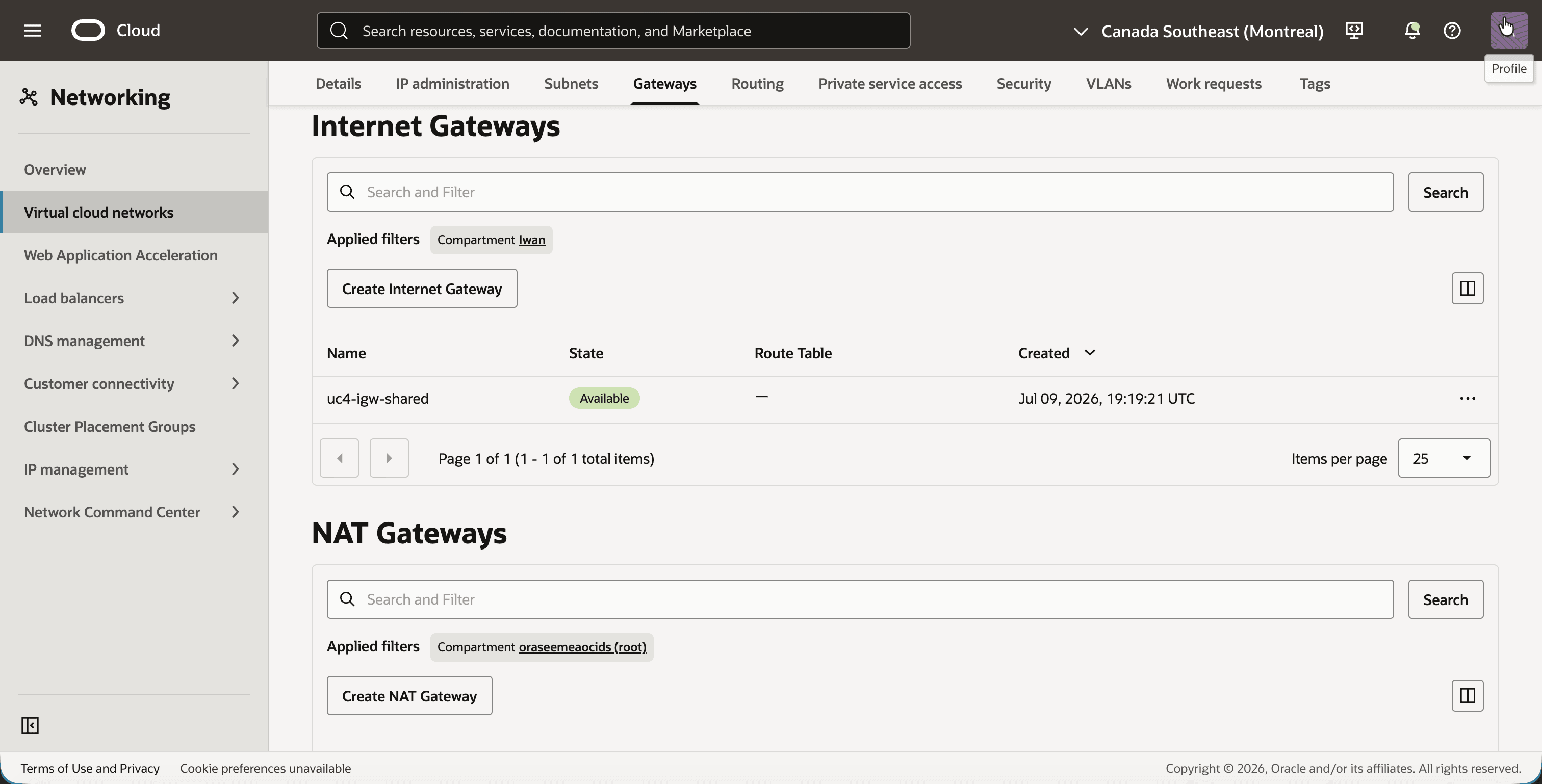
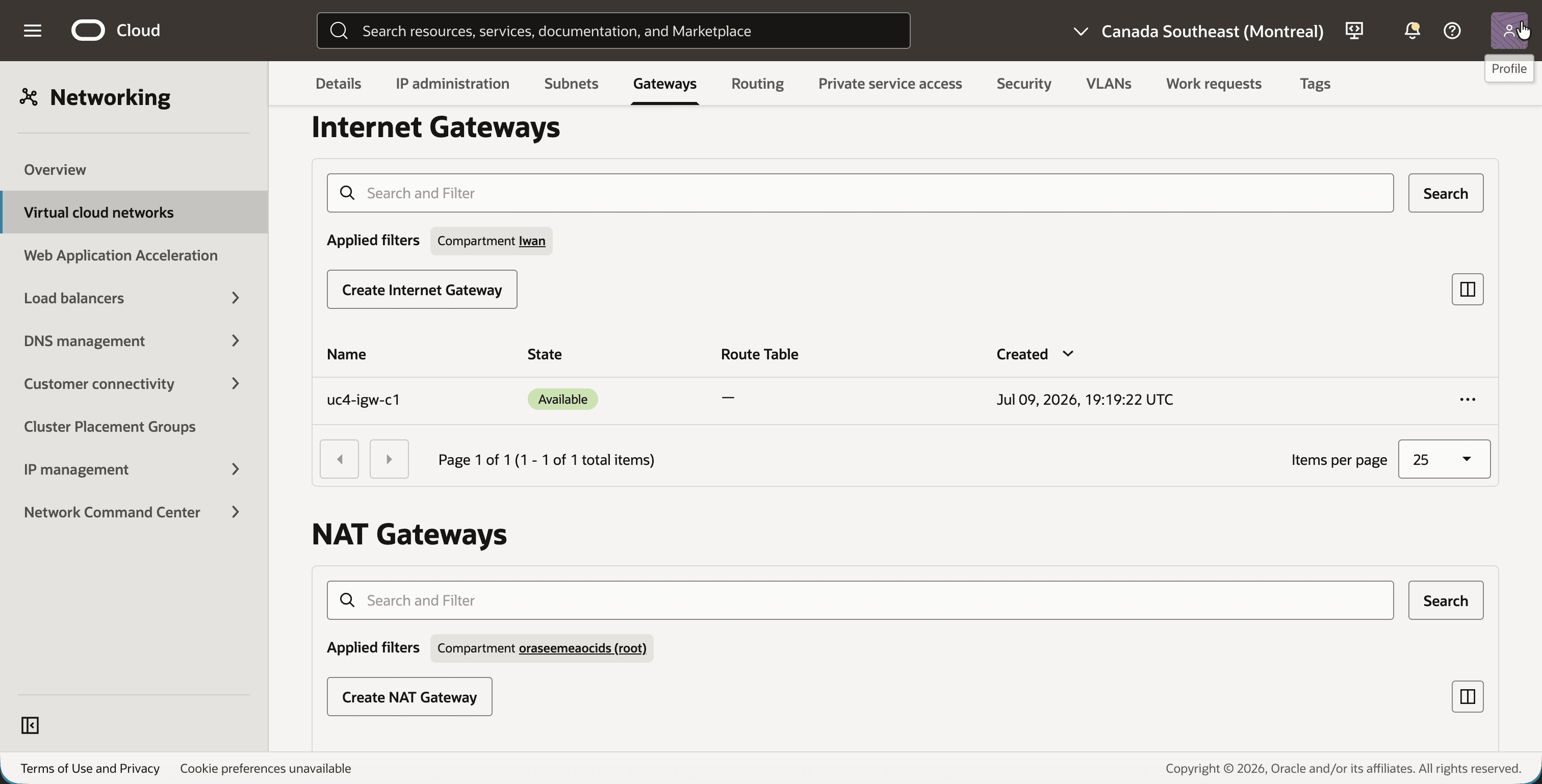
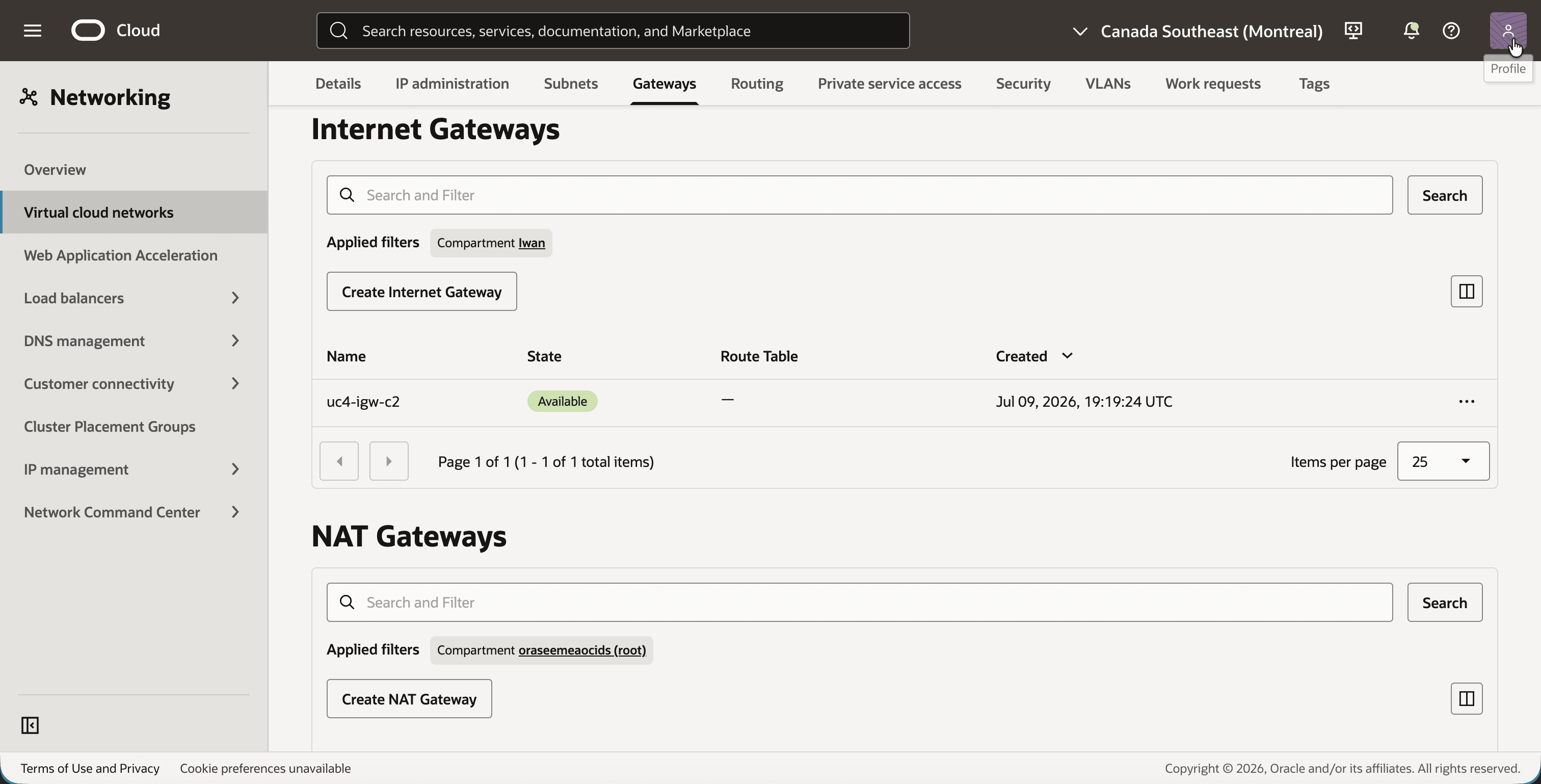
- In
uc4-vcn-shared, click on the Gateways tab. - Notice the internet gateway
uc4-igw-shared.
- In
uc4-vcn-c1, click on the Gateways tab. - Notice the internet gateway
uc4-igw-c1.
- In
uc4-vcn-c2, click on the Gateways tab. - Notice the internet gateway
uc4-igw-c2.
Step 04: Configure the security lists
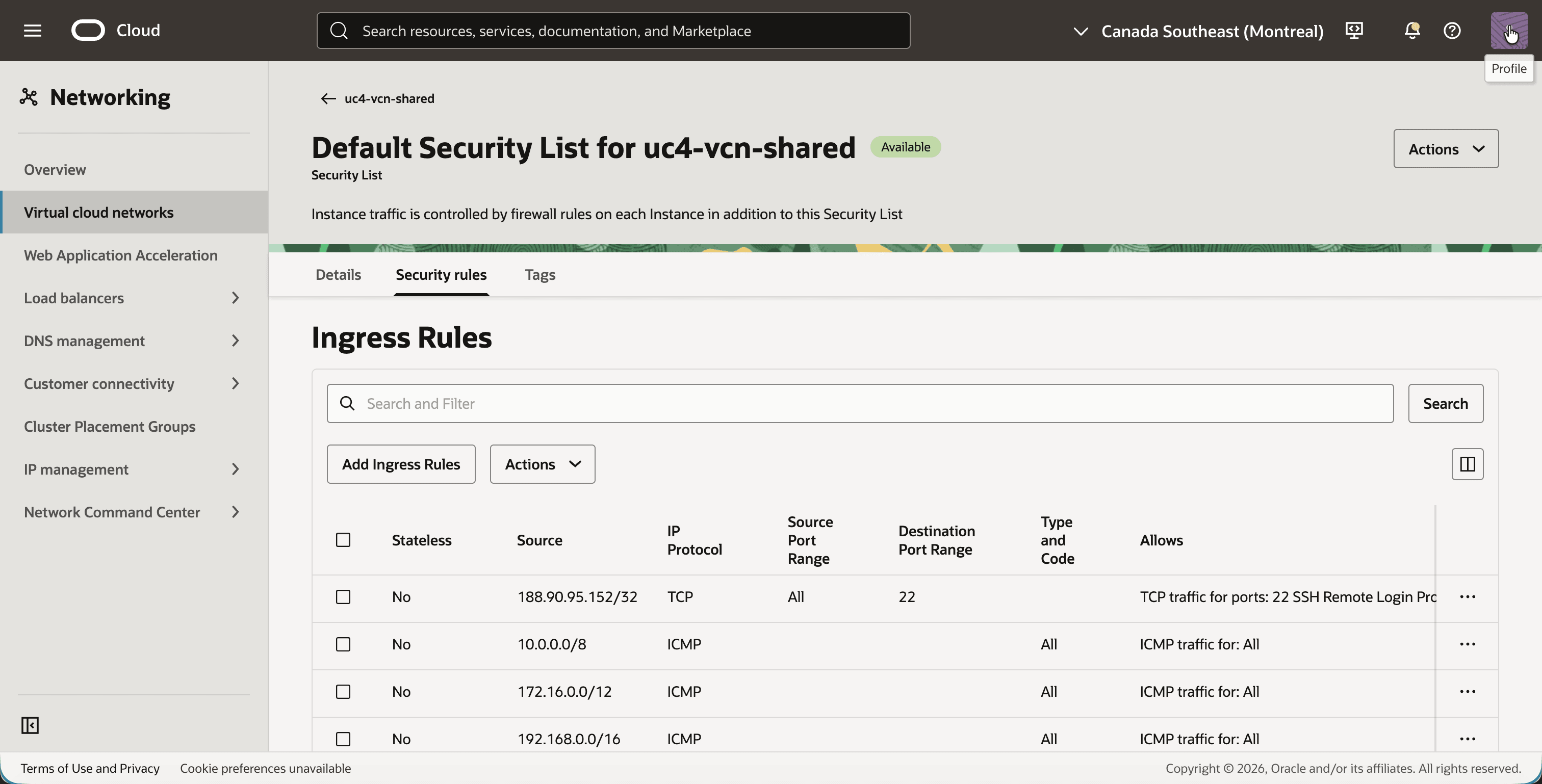
The test in this tutorial is a ping, so the security lists must allow ICMP. The shared services VCN is the interesting one. It never sees a packet from 10.0.1.0/24. Traffic from the customers arrives with a source address in 192.168.10.0/24 or 192.168.20.0/24, so those are the ranges its security rules must allow. In a real deployment this is useful: you can write a separate security rule per customer, even though the customers use the same real addresses.
The lab allows ICMP from all three private ranges. That is broader than this tutorial needs. The shared services VCN only needs ICMP from the two shadow CIDRs 192.168.10.0/24 and 192.168.20.0/24. The customer VCNs only need ICMP from 10.50.0.0/16, and only for pings that start in the shared services VCN.
- In
uc4-vcn-shared, click on the Security tab and click on Default Security List for uc4-vcn-shared. - Click on the Security rules tab.
- Make sure the security list has the following ingress rules, and add the ones that are missing:
- TCP port
22from your own public IP address, for SSH. - ICMP from
10.0.0.0/8,172.16.0.0/12and192.168.0.0/16. The last one covers both shadow CIDRs.
- TCP port
- Configure the same ingress rules in the default security lists of
uc4-vcn-c1anduc4-vcn-c2.
Step 05: Create the DRG and attach the three VCNs
The DRG is the router between the three VCNs and the place where the translation happens. All three VCNs are attached to the same DRG, each with its own VCN attachment. The route tables and the NAT policies in the next steps are all bound to an attachment, not to the DRG as a whole.
- Open the navigation menu, click on Networking, then on Customer connectivity and then on Dynamic routing gateway.
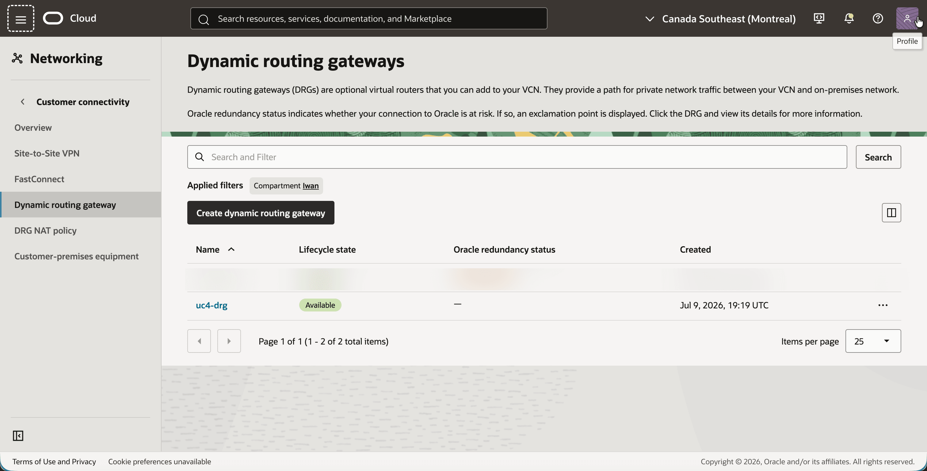
- Click on the Create dynamic routing gateway button and create a DRG with the name
uc4-drg. - Notice that the DRG is Available.
- Click on
uc4-drgand click on the Attachments tab. - Click on the Create virtual cloud network attachment button and create three attachments:
uc4-att-c1for the VCNuc4-vcn-c1.uc4-att-c2for the VCNuc4-vcn-c2.uc4-att-sharedfor the VCNuc4-vcn-shared.
[!NOTE] We come back to this Attachments tab in Step 09. At that point every attachment also shows its own DRG route table, and the customer attachments show their DRG NAT policy.
Step 06: Create a DRG route table for each attachment
A DRG route table decides where a packet goes after it has entered the DRG through an attachment. By default all VCN attachments share one autogenerated route table that is filled with the CIDRs of the attached VCNs. With two customers that advertise the same 10.0.1.0/24, the DRG keeps only one of the two routes in that table and marks the other one as a conflict. That conflict is not what breaks this design, because nothing here is ever routed to 10.0.1.0/24. The problem is the way back: replies from the shared services VCN are addressed to the shadow CIDRs, and no attachment advertises those, so the autogenerated table has no route for them. A shared table would also give every attachment the same routes, while the customers should only see the shared services VCN. Each attachment therefore gets its own DRG route table with static routes.
There are two things to notice in these tables:
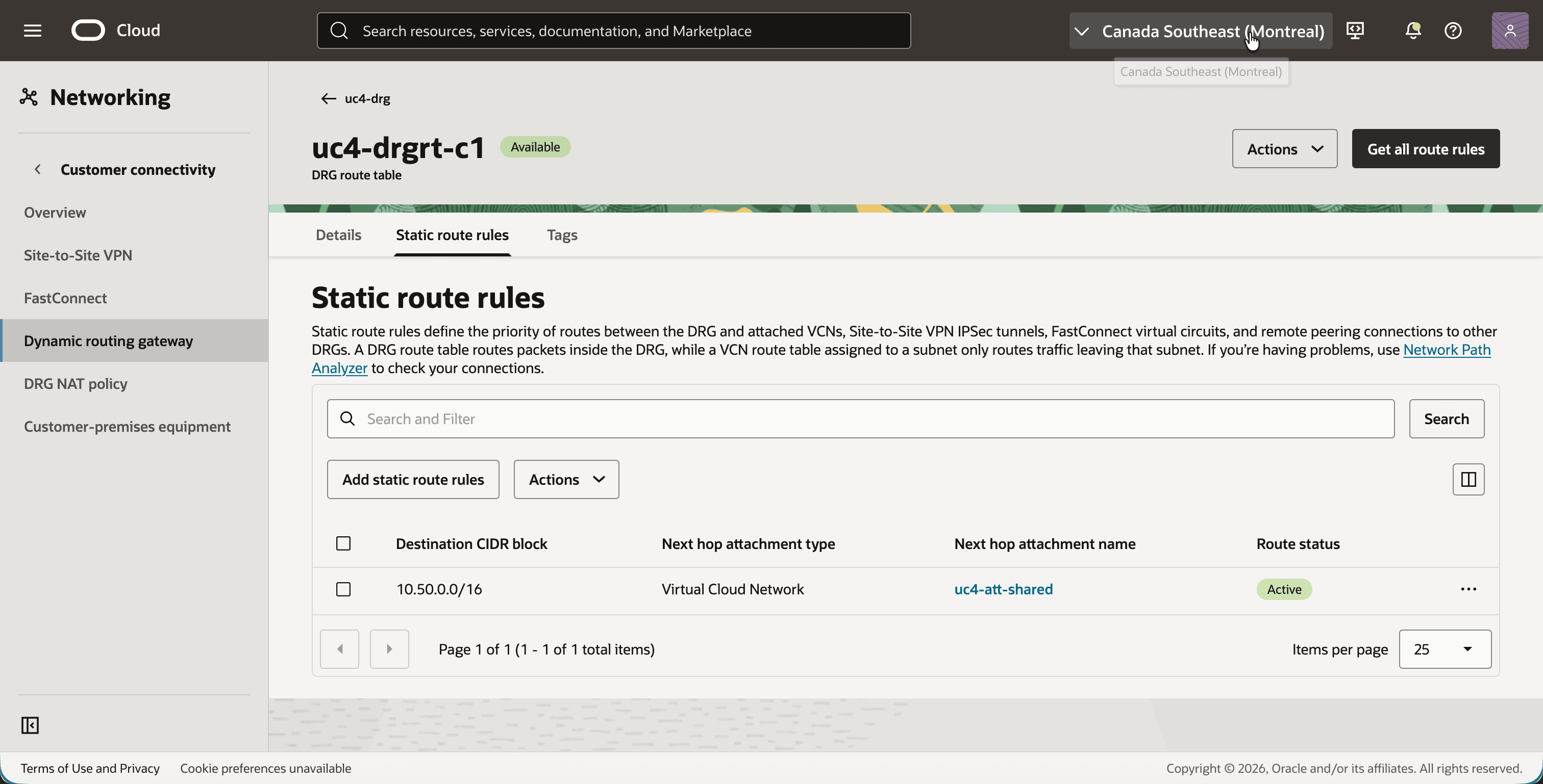
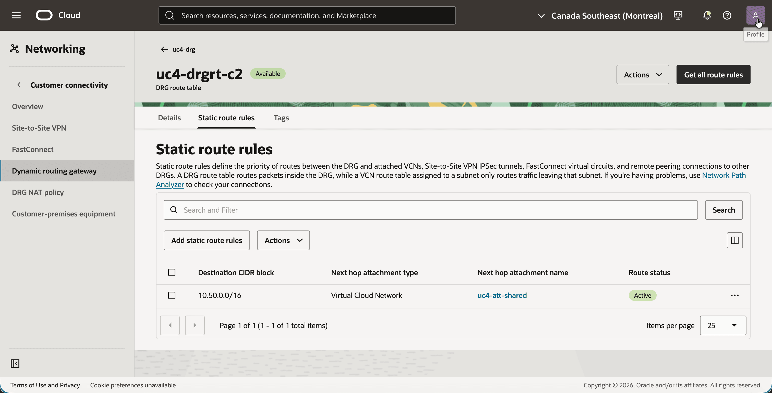
- The customer tables only contain the shared services VCN. Traffic entering from a customer can go to
10.50.0.0/16and nowhere else. There is no route from one customer to the other, so the customers stay isolated from each other. -
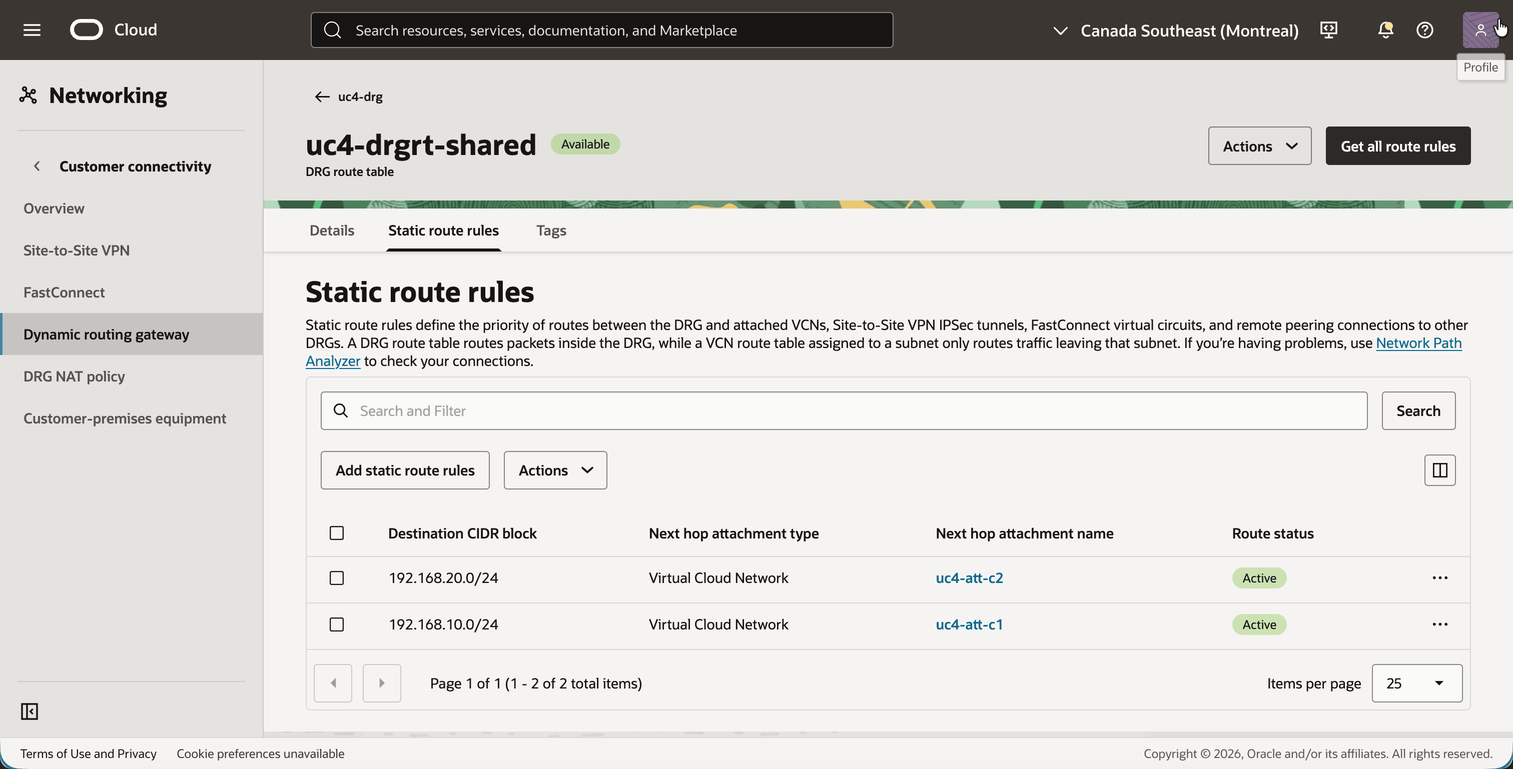
The shared table routes on the shadow CIDRs. A reply from the shared services VCN is addressed to
192.168.10.xor192.168.20.x. The shadow CIDR is what tells the DRG which customer the packet belongs to. - In
uc4-drg, click on the Routing tab and create a DRG route table with the nameuc4-drgrt-c1. - Click on the Static route rules tab and click on the Add static route rules button.
- Add a rule with the Destination CIDR block
10.50.0.0/16and the Next hop attachmentuc4-att-shared. - Notice that the static route is Active.
- Create a second DRG route table with the name
uc4-drgrt-c2. - Add the same static route rule: Destination CIDR block
10.50.0.0/16with the Next hop attachmentuc4-att-shared. - Notice that the static route is Active.
- Create a third DRG route table with the name
uc4-drgrt-shared. - Add two static route rules:
- Destination CIDR block
192.168.10.0/24with the Next hop attachmentuc4-att-c1. - Destination CIDR block
192.168.20.0/24with the Next hop attachmentuc4-att-c2.
- Destination CIDR block
- Notice that both static routes are Active.
- Go back to the Attachments tab of
uc4-drgand edit each attachment to select its DRG route table:uc4-att-c1usesuc4-drgrt-c1.uc4-att-c2usesuc4-drgrt-c2.uc4-att-sharedusesuc4-drgrt-shared.
Step 07: Configure the VCN route tables
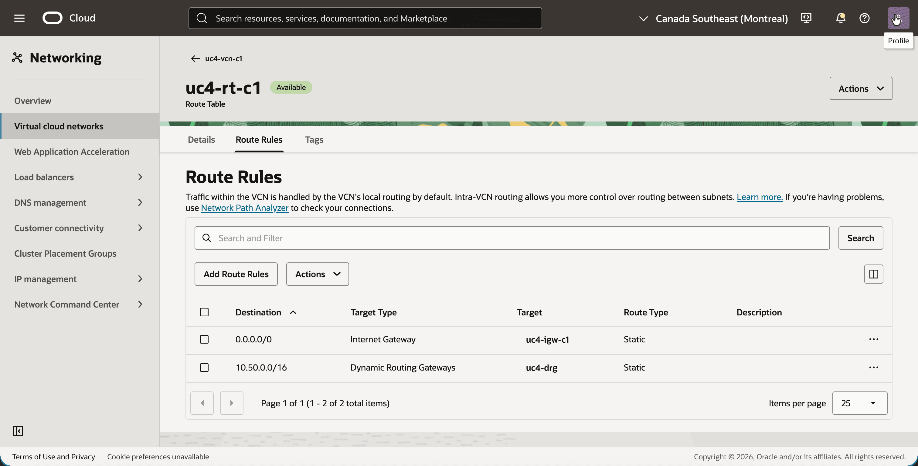
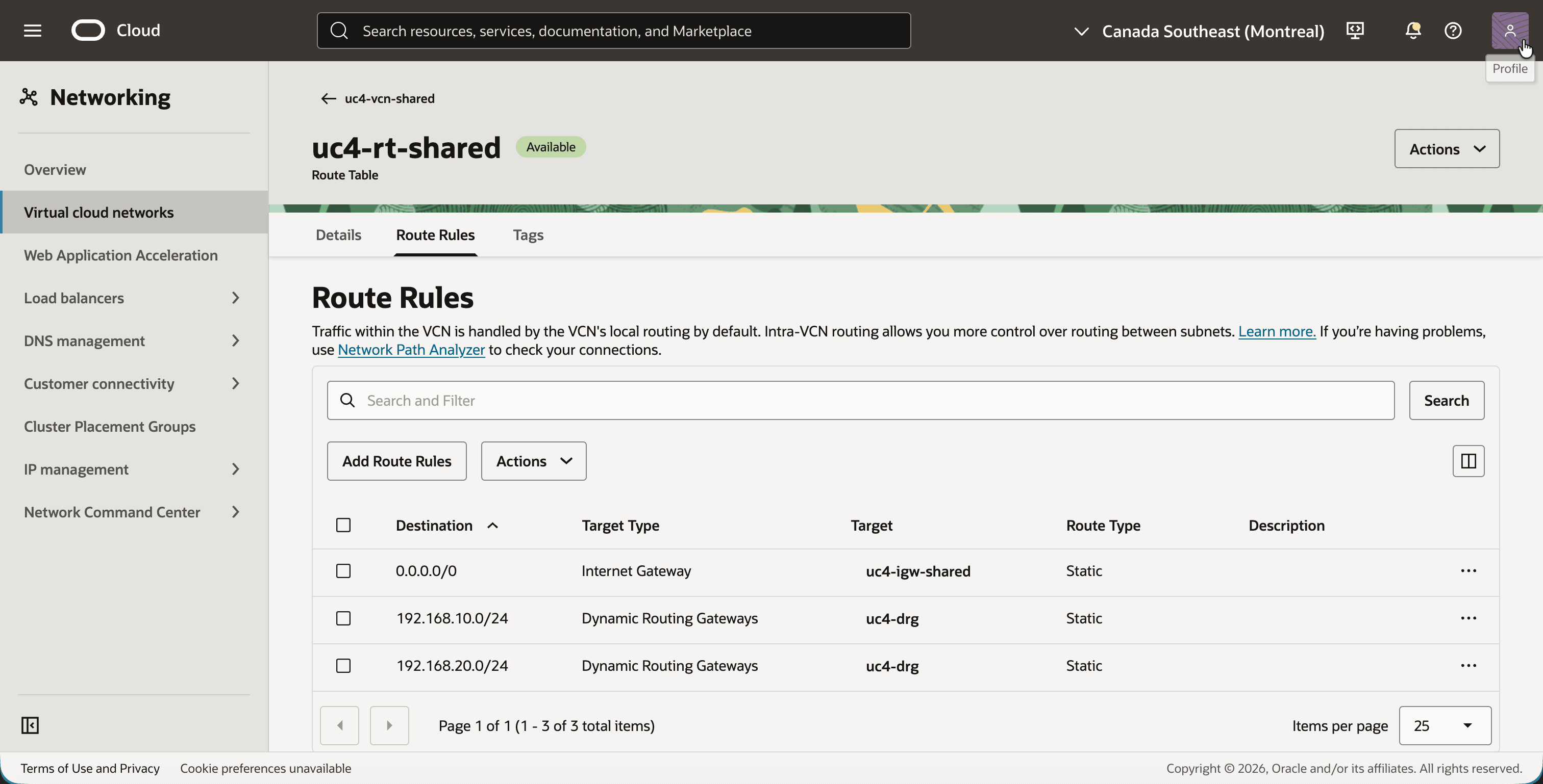
The instances must know which destinations are reachable through the DRG. The customers talk to the real addresses of the shared services VCN, so they route 10.50.0.0/16 to the DRG. The shared services VCN talks to the customers on their shadow addresses, so it routes both shadow CIDRs to the DRG.
- In
uc4-vcn-c1, click on the Routing tab and click on the route tableuc4-rt-c1. This is the route table that is assigned touc4-subnet-c1. - Click on the Route Rules tab.
- Add a route rule for the shared services VCN, so that the route table has these two route rules:
0.0.0.0/0with the targetuc4-igw-c1, for SSH access from the internet.10.50.0.0/16(the shared services VCN) with the targetuc4-drg.
- In
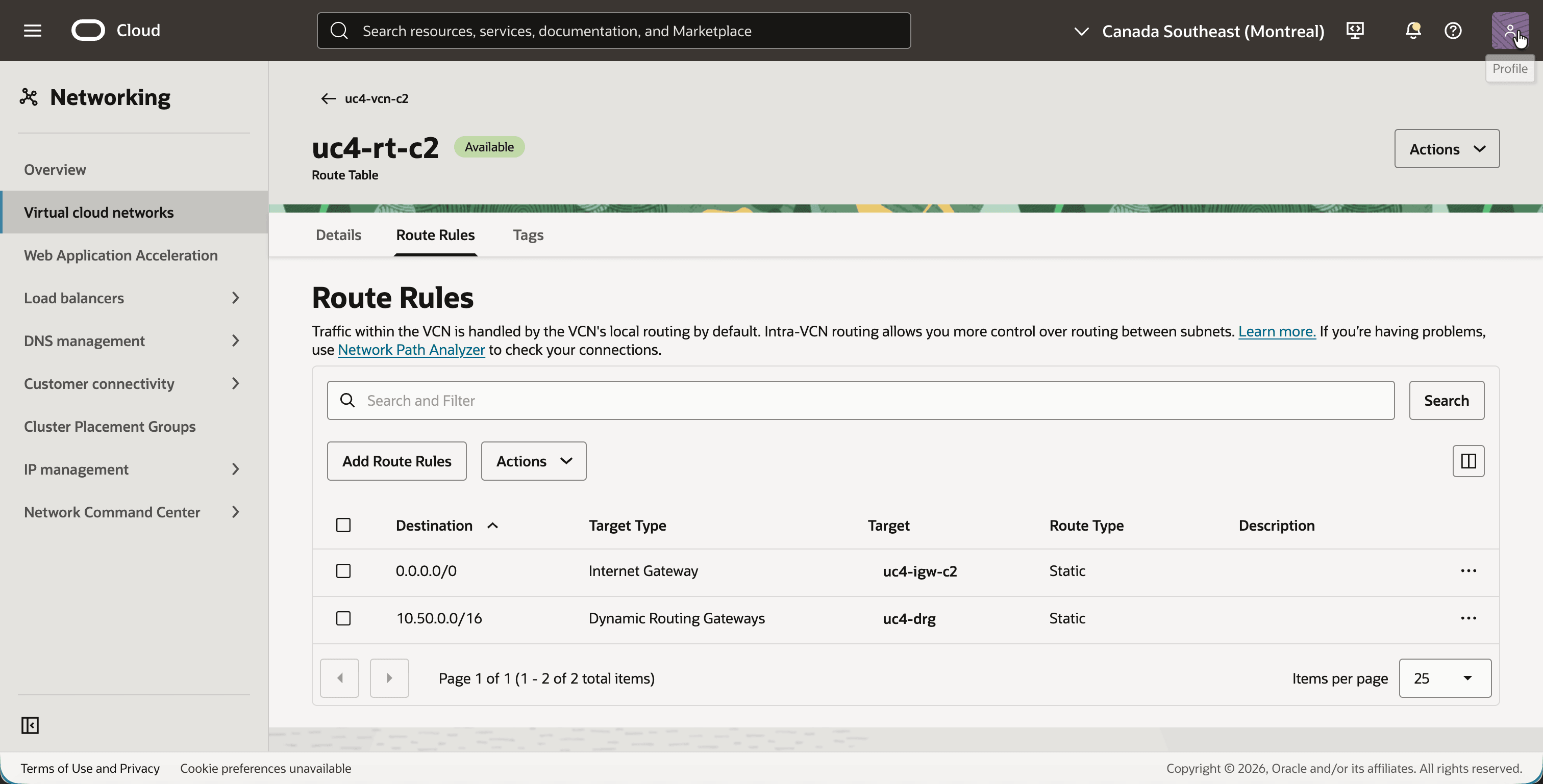
uc4-vcn-c2, open the route tableuc4-rt-c2in the same way. - Add a route rule for the shared services VCN, so that the route table has these two route rules:
0.0.0.0/0with the targetuc4-igw-c2.10.50.0.0/16with the targetuc4-drg.
- In
uc4-vcn-shared, open the route tableuc4-rt-sharedin the same way. - Add a route rule for each shadow CIDR, so that the route table has these three route rules:
0.0.0.0/0with the targetuc4-igw-shared.192.168.10.0/24(the shadow CIDR of customer 1) with the targetuc4-drg.192.168.20.0/24(the shadow CIDR of customer 2) with the targetuc4-drg.
Step 08: Create the DRG NAT policies and rules
This is the step the whole tutorial is about. We create one DRG NAT policy per customer, and each policy gets one rule. The rule only translates the source address:
| Policy | Original source | Translated source | Meaning |
|---|---|---|---|
uc4-policy-c1 |
10.0.1.0/24 |
192.168.10.0/24 |
Customer 1 presents itself as 192.168.10.0/24. |
uc4-policy-c2 |
10.0.1.0/24 |
192.168.20.0/24 |
Customer 2 presents itself as 192.168.20.0/24. |
The destination is left alone. The customers address the shared services on their real 10.50.x.x addresses, and those are unique, so there is nothing to translate.
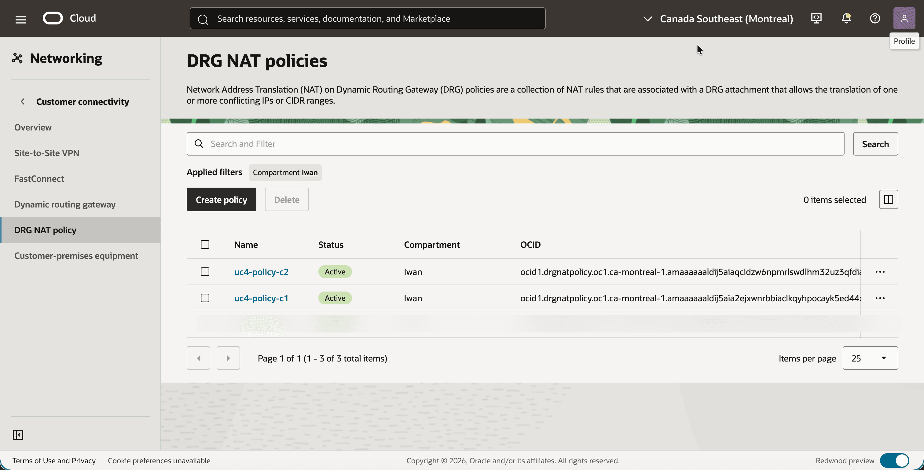
- Open the navigation menu, click on Networking, then on Customer connectivity and then on DRG NAT policy.
- Click on the Create policy button and create a policy with the name
uc4-policy-c1. - Create a second policy with the name
uc4-policy-c2. - Notice that both policies are Active.
- Click on
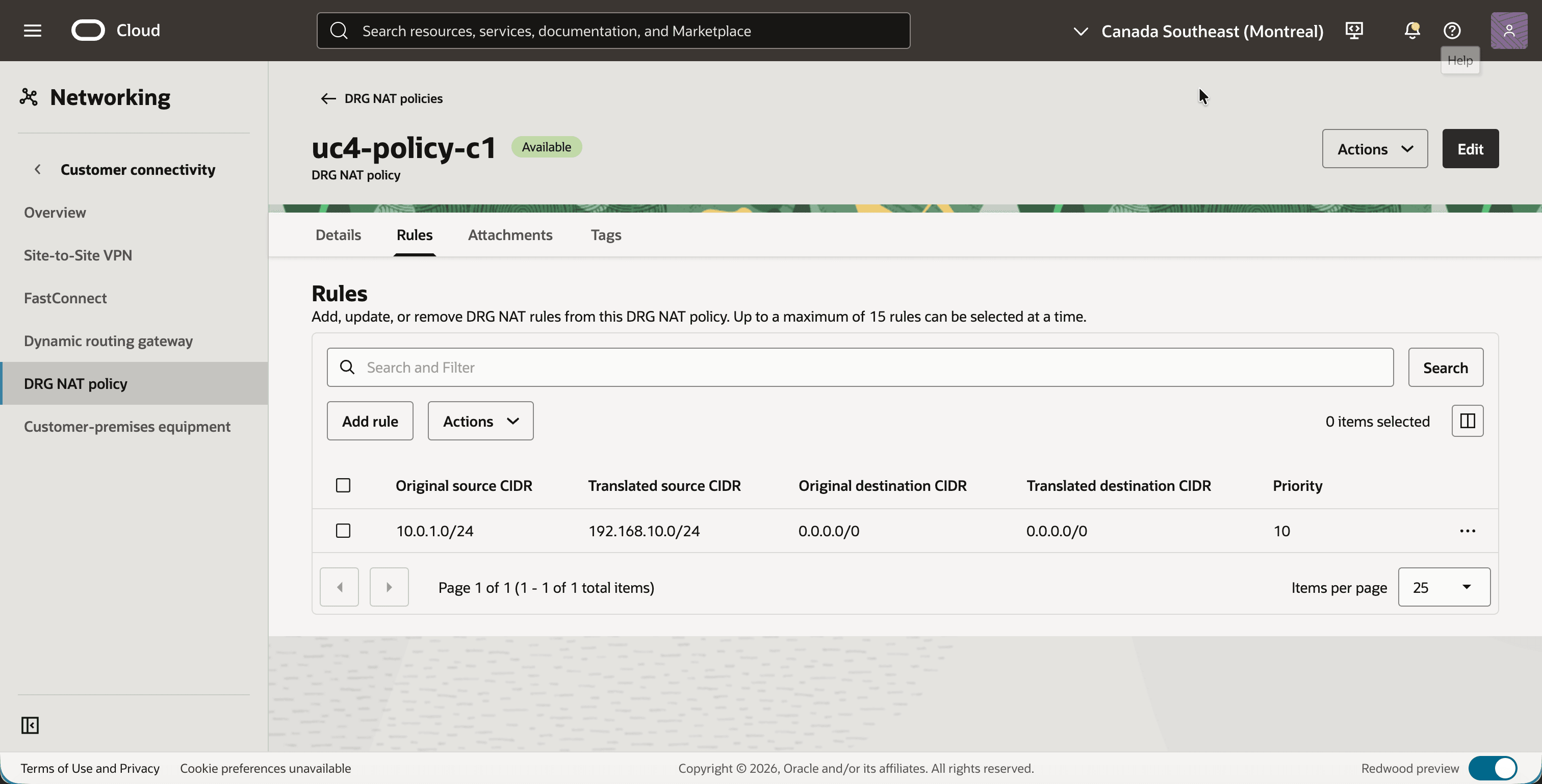
uc4-policy-c1and click on the Rules tab. - Click on the Add rule button and add a rule with the following values:
- Priority:
10 - Original source CIDR:
10.0.1.0/24 - Translated source CIDR:
192.168.10.0/24 - Original destination CIDR: leave empty
- Translated destination CIDR: leave empty
- Priority:
- Notice that the rule is listed on the Rules tab. The destination columns show
0.0.0.0/0, which means that the rule matches any destination and does not translate it.
- Go back, click on
uc4-policy-c2and click on the Rules tab. - Click on the Add rule button and add a rule with the following values:
- Priority:
10 - Original source CIDR:
10.0.1.0/24 - Translated source CIDR:
192.168.20.0/24 - Original destination CIDR: leave empty
- Translated destination CIDR: leave empty
- Priority:
- Notice that the rule is listed on the Rules tab.
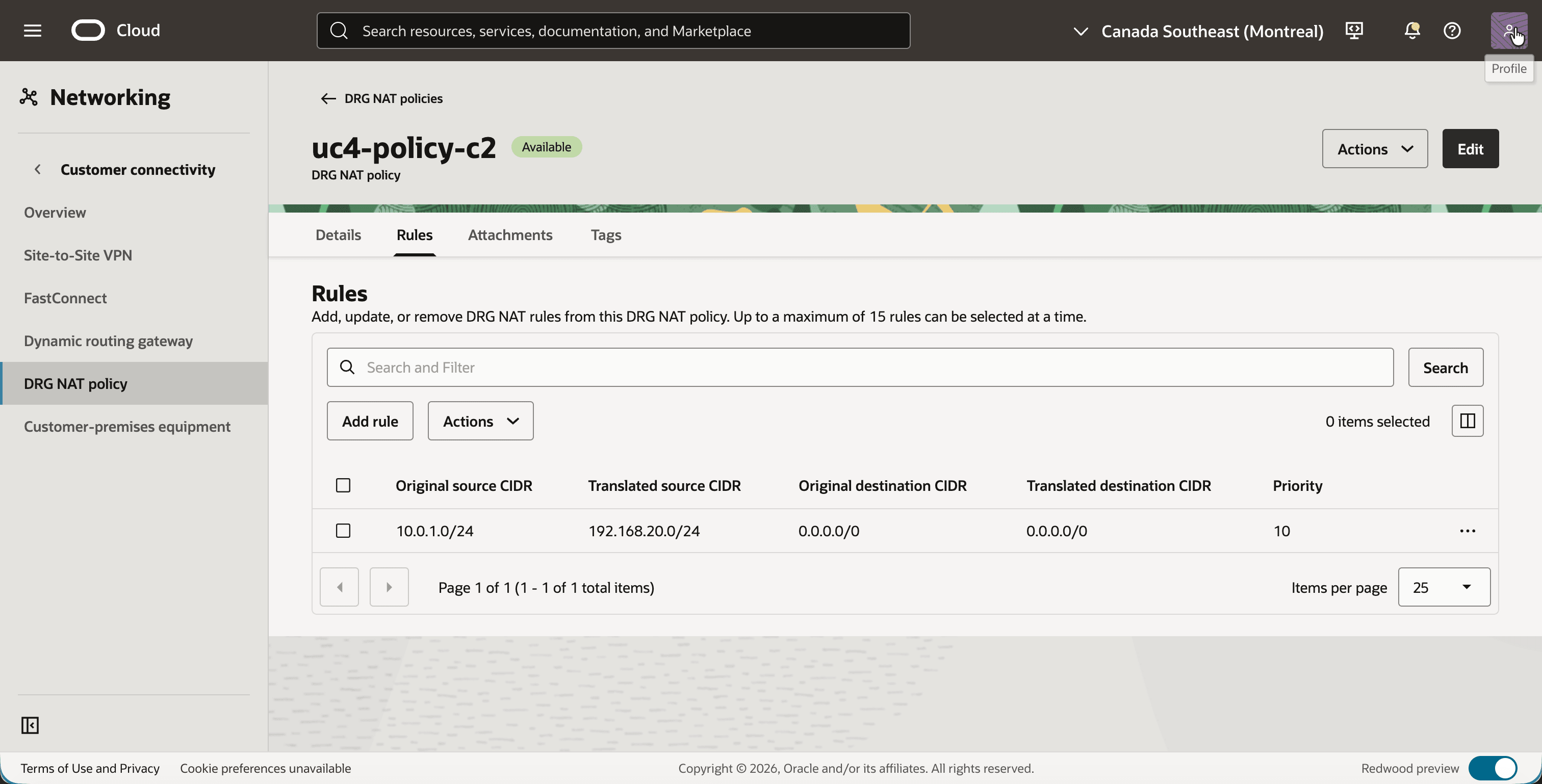
[!NOTE] The two rules look almost identical, and they both match the same original source
10.0.1.0/24. That is not a conflict. Each policy is bound to its own attachment, and a packet is only checked against the policy of the attachment it crosses.
Step 09: Associate the NAT policies with the customer attachments
A policy becomes active for traffic when it is associated with a DRG attachment. Each attachment can have one NAT policy. We associate the two policies with the two customer attachments. The attachment of the shared services VCN gets no policy.
- Click on
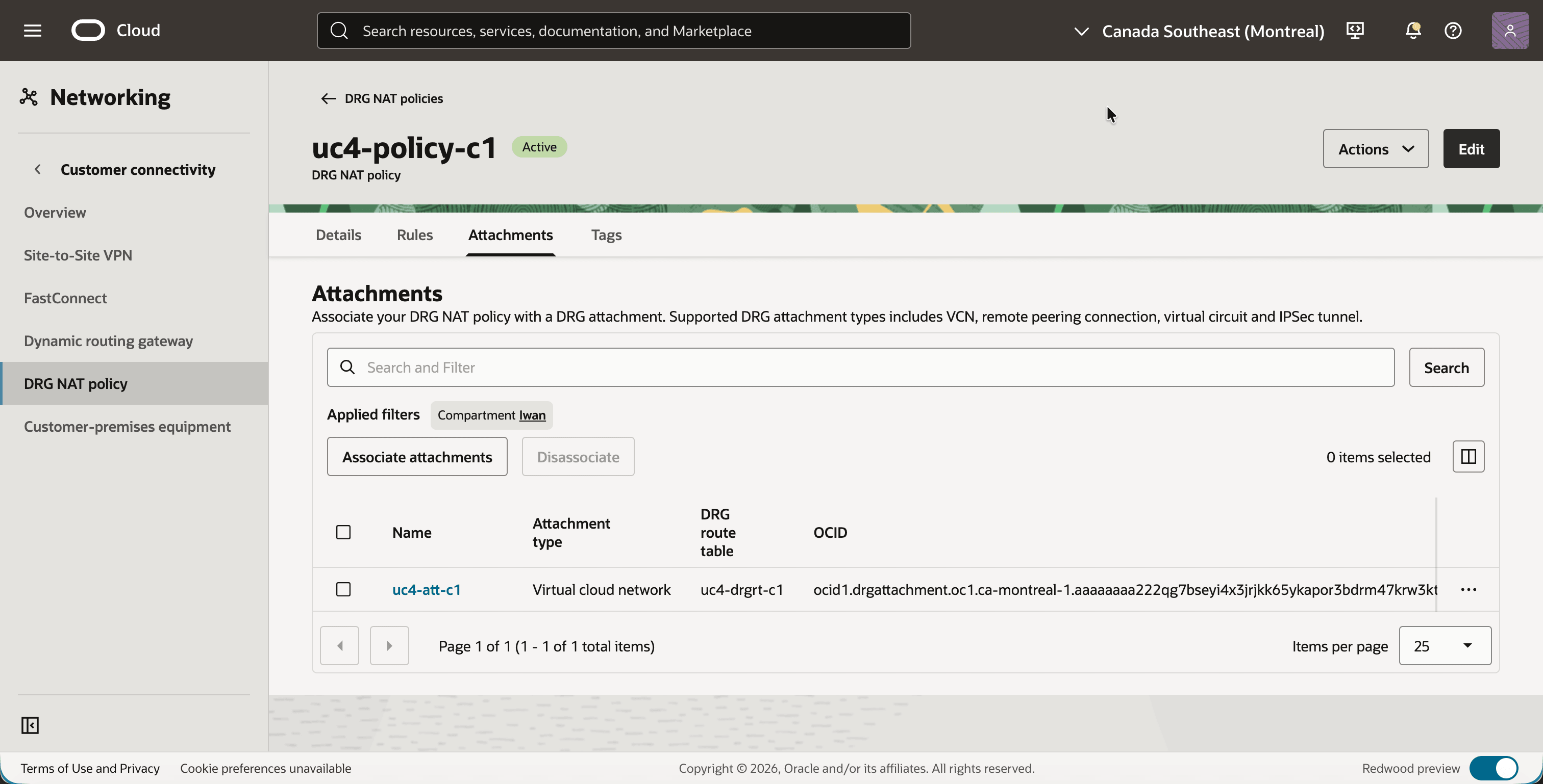
uc4-policy-c1and click on the Attachments tab. - Click on the Associate attachments button, select
uc4-att-c1and confirm. - Notice that
uc4-att-c1is listed, together with its DRG route tableuc4-drgrt-c1.
- Click on
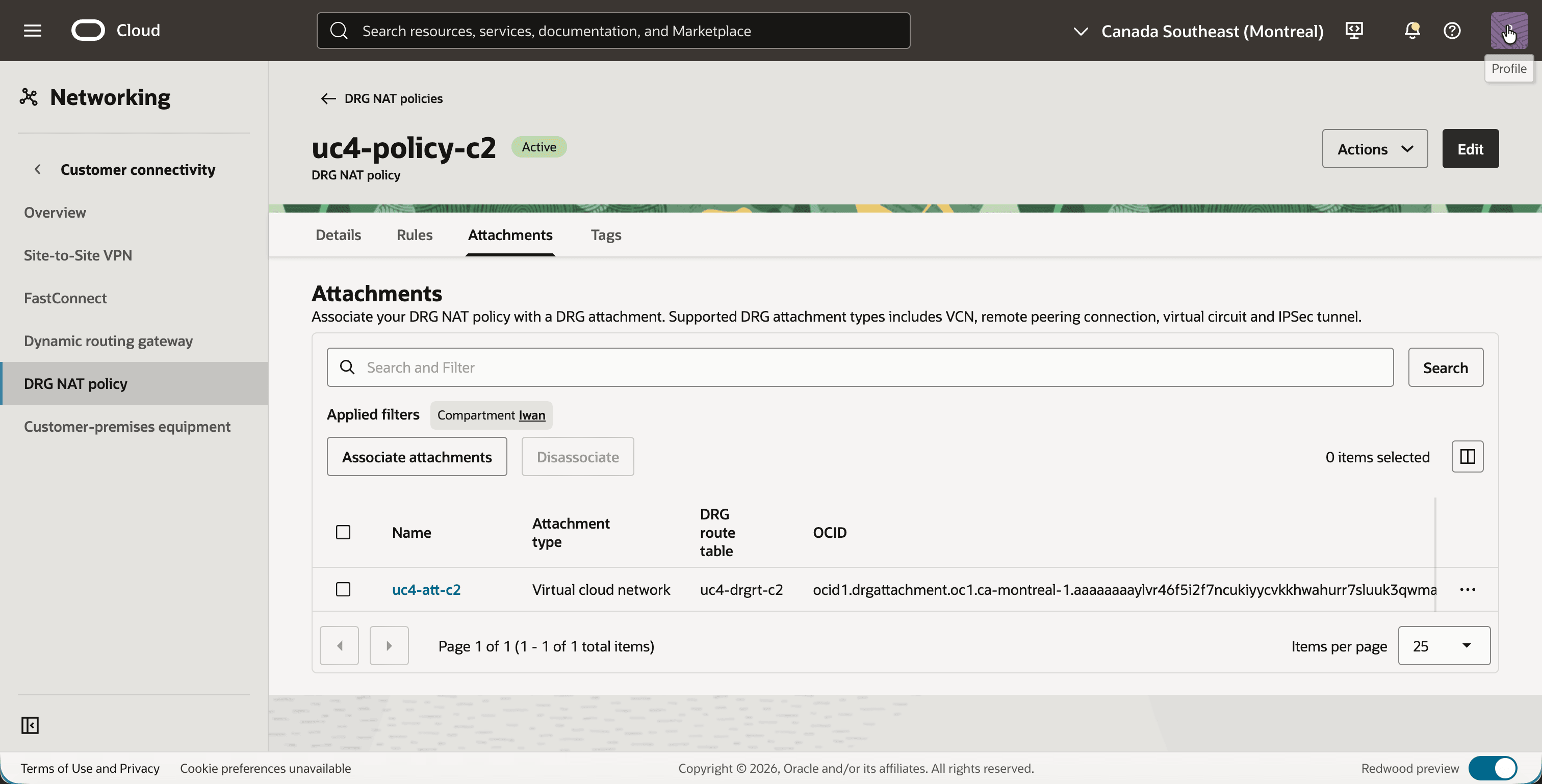
uc4-policy-c2and click on the Attachments tab. - Click on the Associate attachments button, select
uc4-att-c2and confirm. - Notice that
uc4-att-c2is listed, together with its DRG route tableuc4-drgrt-c2.
You can verify the complete configuration from the DRG side as well.
- Open the navigation menu, click on Networking, then on Customer connectivity and then on Dynamic routing gateway.
- Click on
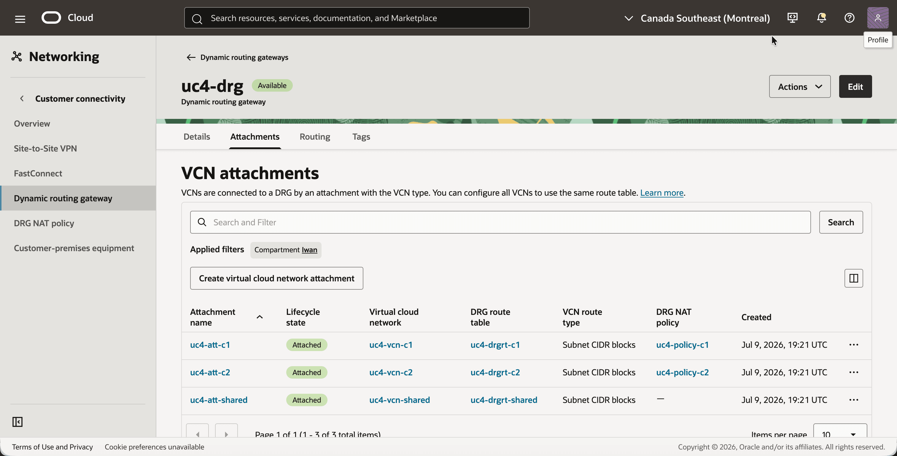
uc4-drgand click on the Attachments tab. - Notice that each attachment has its own DRG route table, and that only the two customer attachments have a DRG NAT policy.
- Click on the attachment
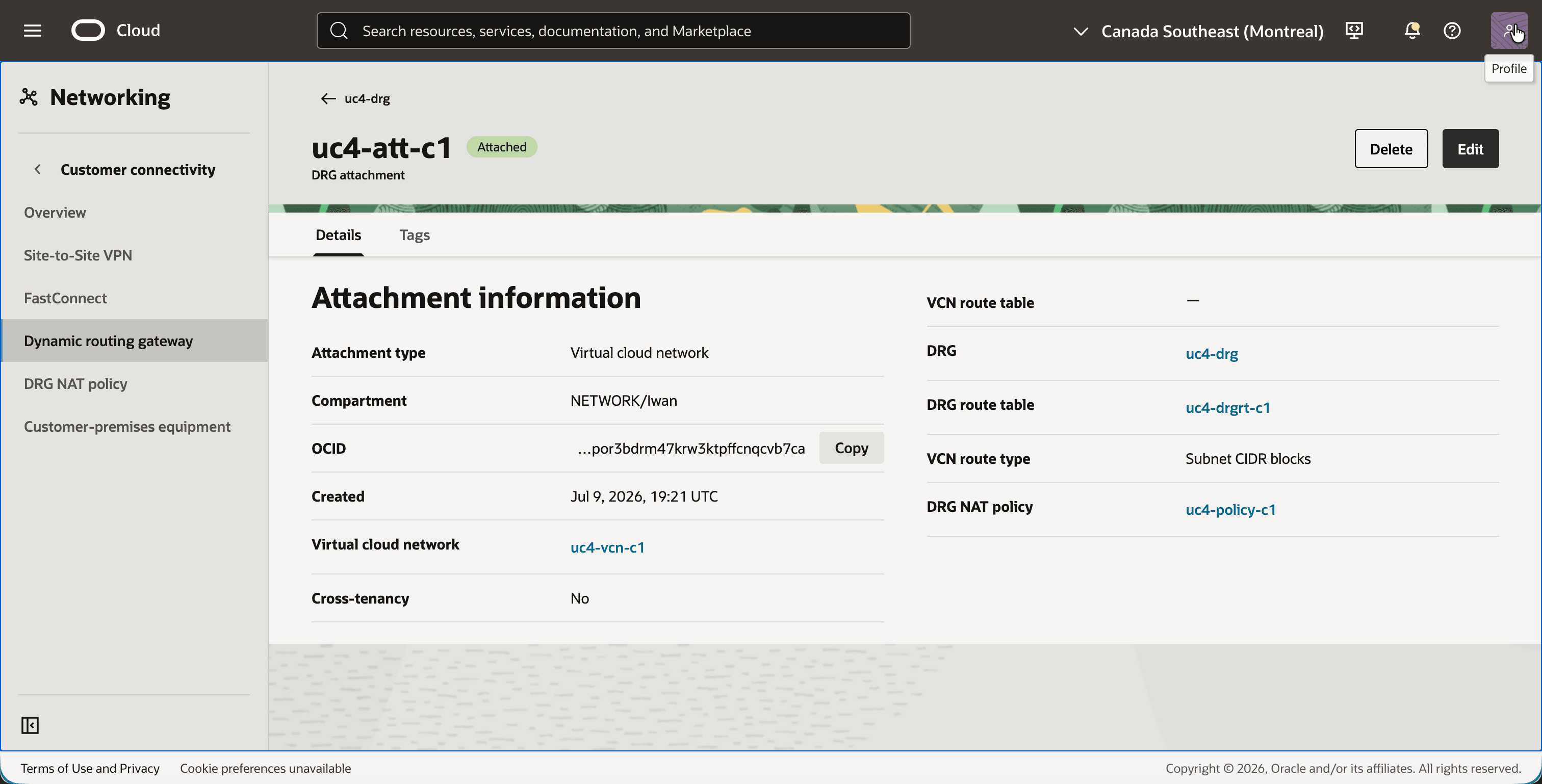
uc4-att-c1. - Notice the DRG route table
uc4-drgrt-c1and the DRG NAT policyuc4-policy-c1.
- Go back and click on the attachment
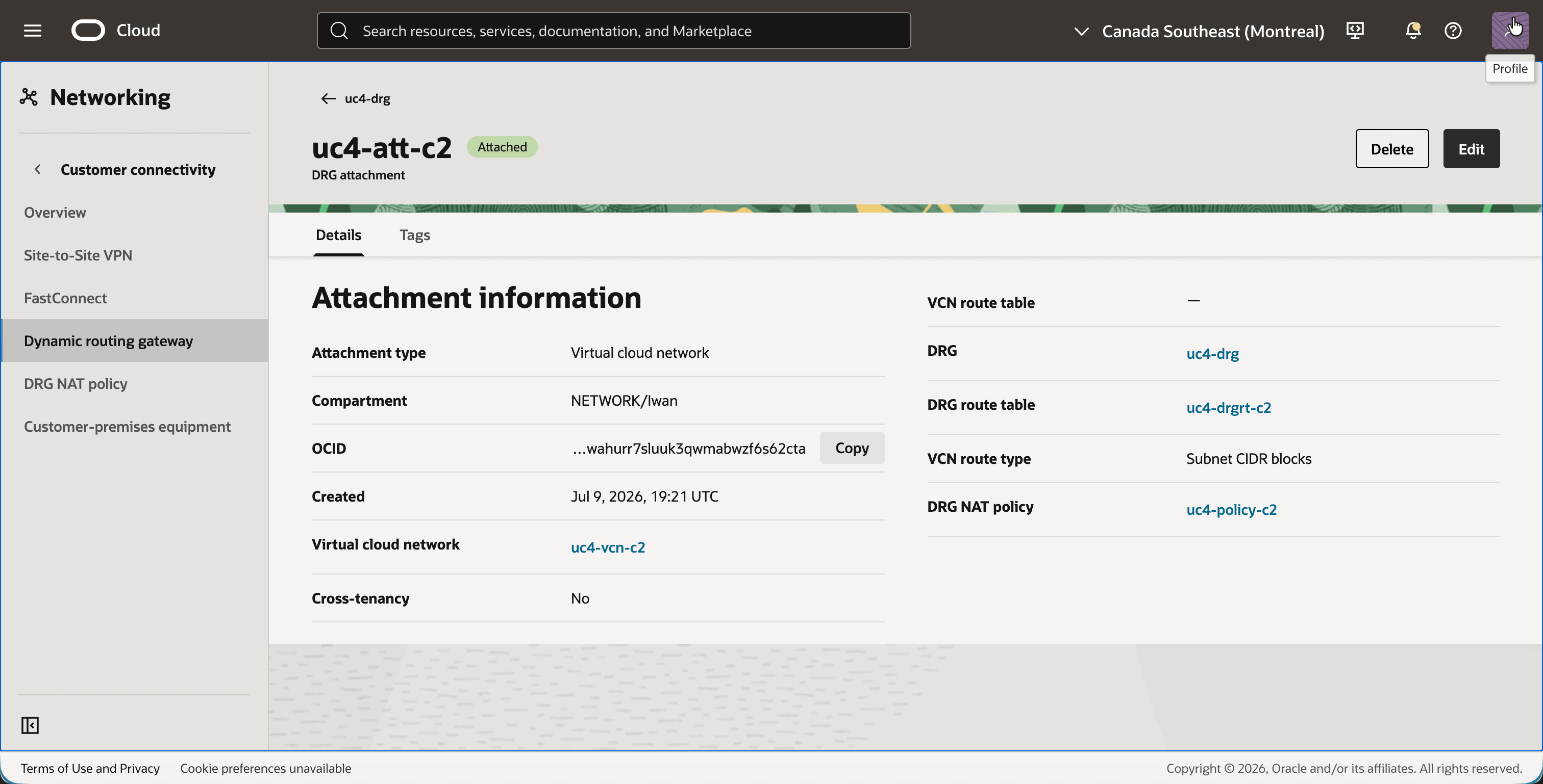
uc4-att-c2. - Notice the DRG route table
uc4-drgrt-c2and the DRG NAT policyuc4-policy-c2.
- Go back and click on the attachment
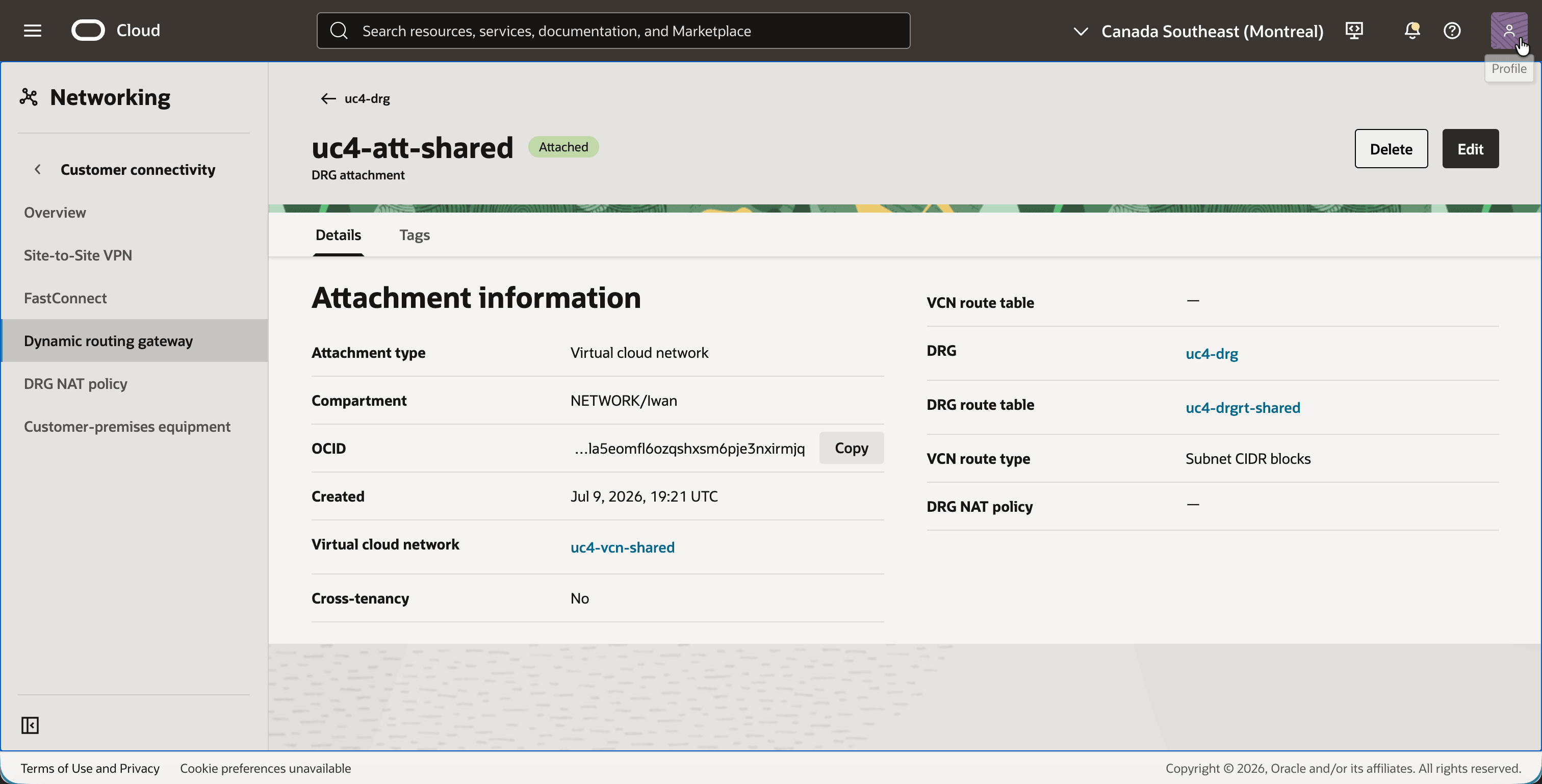
uc4-att-shared. - Notice the DRG route table
uc4-drgrt-shared, and notice that the DRG NAT policy field is empty.
Step 10: Test the connectivity
Everything is in place, so it is time to send some packets. The last octet of an address is preserved by the 1:1 translation, which tells you under which address the shared services VCN knows each customer instance:
| Instance | Real IP address | Address seen by the shared services VCN |
|---|---|---|
uc4-inst-c1 |
10.0.1.13 |
192.168.10.13 |
uc4-inst-c2 |
10.0.1.171 |
192.168.20.171 |
uc4-inst-shared |
10.50.1.51 |
Not translated |
This is what happens to a ping from uc4-inst-c1 to uc4-inst-shared:
| Where | Source | Destination | What happens |
|---|---|---|---|
Leaves uc4-inst-c1 |
10.0.1.13 |
10.50.1.51 |
The route table uc4-rt-c1 sends 10.50.0.0/16 to the DRG. |
Enters the DRG on uc4-att-c1 |
192.168.10.13 |
10.50.1.51 |
The rule in uc4-policy-c1 translates the source. |
Route lookup in uc4-drgrt-c1 |
192.168.10.13 |
10.50.1.51 |
10.50.0.0/16 points to uc4-att-shared. |
Arrives at uc4-inst-shared |
192.168.10.13 |
10.50.1.51 |
The instance sees a ping from the shadow address of customer 1. |
And this is the reply:
| Where | Source | Destination | What happens |
|---|---|---|---|
Leaves uc4-inst-shared |
10.50.1.51 |
192.168.10.13 |
The route table uc4-rt-shared sends 192.168.10.0/24 to the DRG. |
Enters the DRG on uc4-att-shared |
10.50.1.51 |
192.168.10.13 |
No NAT policy on this attachment, so nothing is translated. |
Route lookup in uc4-drgrt-shared |
10.50.1.51 |
192.168.10.13 |
192.168.10.0/24 points to uc4-att-c1. |
Leaves the DRG on uc4-att-c1 |
10.50.1.51 |
10.0.1.13 |
The DRG applies the reverse of the rule in uc4-policy-c1. |
First we test from the customers to the shared services.
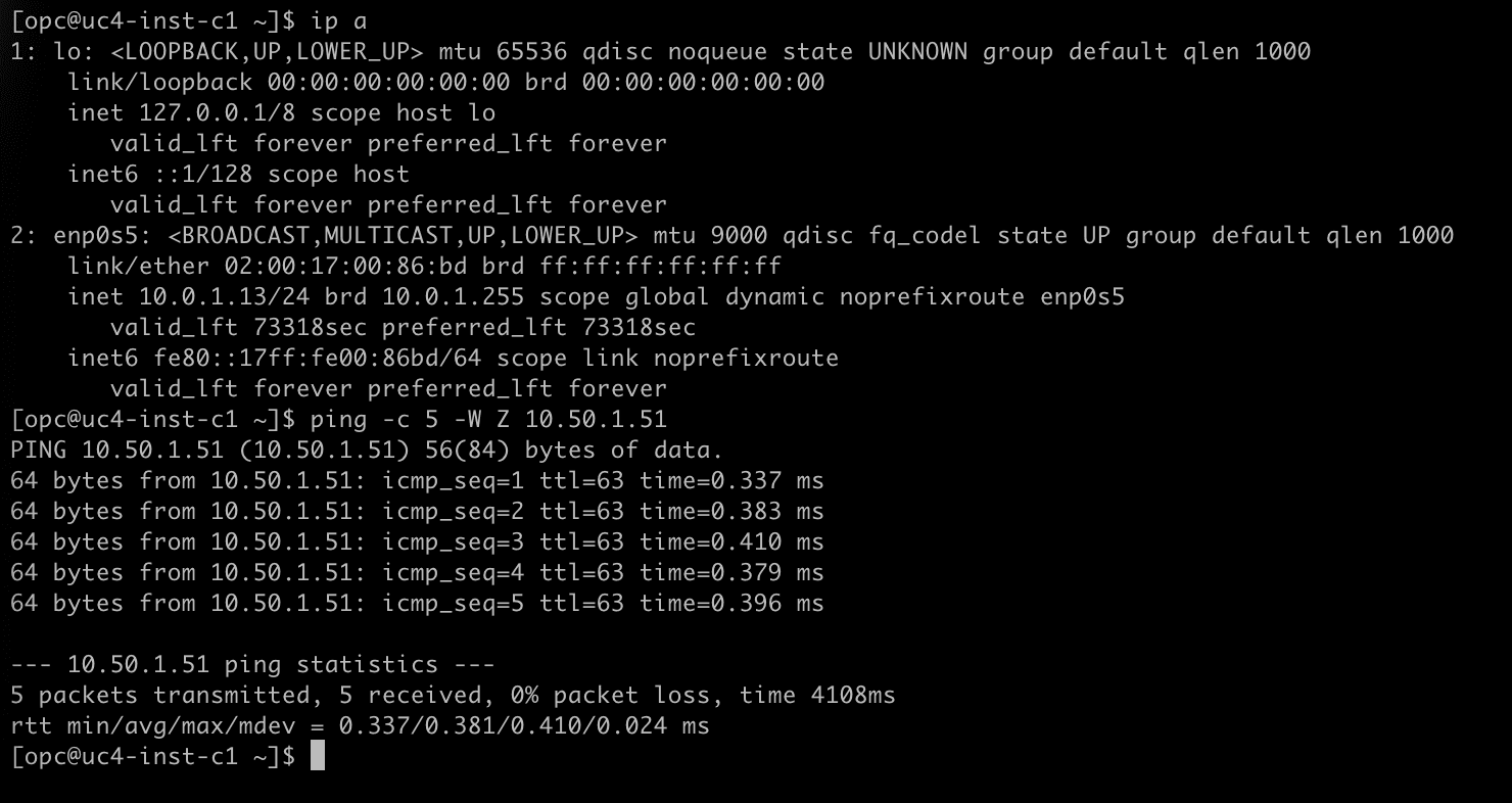
- Connect to
uc4-inst-c1with SSH. - Run
ip aand notice that the instance has the IP address10.0.1.13. - Run
ping -c 5 -W 2 10.50.1.51to ping the shared services instance on its real address. - Notice that all five packets are answered.
- Connect to
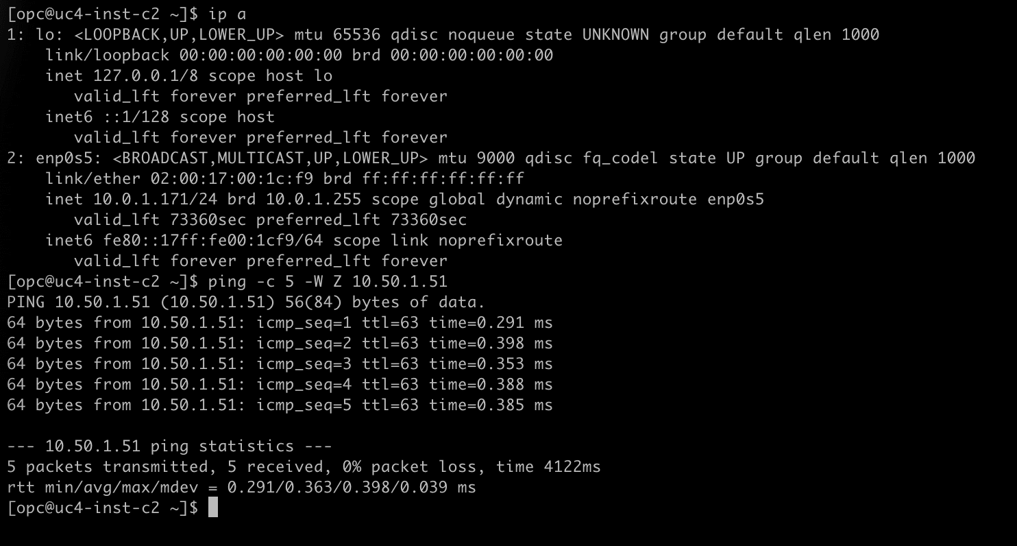
uc4-inst-c2with SSH. - Run
ip aand notice that the instance has the IP address10.0.1.171, in the same subnet range as customer 1. - Run
ping -c 5 -W 2 10.50.1.51. - Notice that all five packets are answered.
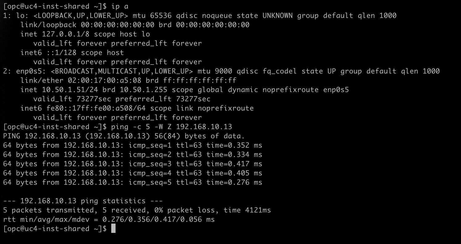
The shared services VCN can also start the conversation. It reaches each customer on its shadow address, and the DRG translates the destination back to the real address when the packet leaves through the customer attachment.
- Connect to
uc4-inst-sharedwith SSH. - Run
ip aand notice that the instance has the IP address10.50.1.51. - Run
ping -c 5 -W 2 192.168.10.13to ping the instance of customer 1. - Notice that all five packets are answered.
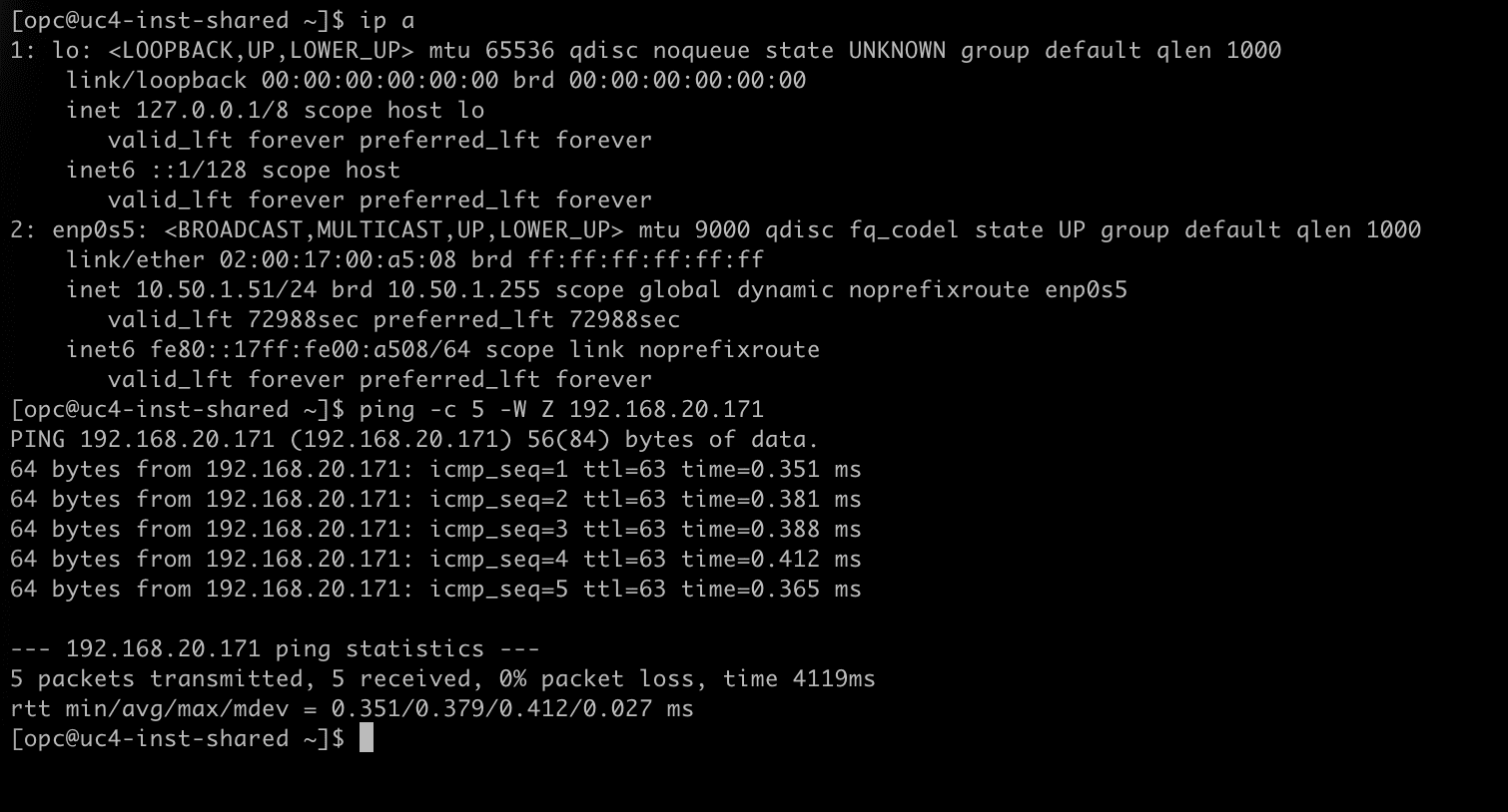
- On the same instance, run
ping -c 5 -W 2 192.168.20.171to ping the instance of customer 2. - Notice that all five packets are answered.
[!NOTE] NAT on DRG does not translate DNS. If the shared services need to find the customer systems by name, the DNS records they use must point to the shadow addresses, not to the real ones.
Conclusion
Two customers with exactly the same subnet CIDR now use the same shared services VCN, and the shared services can tell them apart. The only thing that was added to a normal hub-and-spoke design is a source NAT rule on each customer attachment. The shared services VCN itself needs no NAT policy and no knowledge of the real customer addresses.
The design also scales in a predictable way. Adding a third customer means one more VCN attachment, one more NAT policy with a new shadow CIDR, one more DRG route table that points to the shared services VCN, and one more route in uc4-drgrt-shared and uc4-rt-shared. Nothing changes for the existing customers, and because the customer route tables only contain the shared services VCN, the customers remain isolated from each other.
Part 1 translated between two VCNs on the same DRG, Part 2 moved the translation to a remote peering connection between regions, Part 3 applied it to an IPSec tunnel towards on-premises, and this part used source NAT only to make overlapping consumers unique for a shared service. NAT on DRG - Part 5 - Overlapping CIDRs between OCI and On-Premises with BGP repeats the on-premises use case with BGP dynamic routing. In all of them the method is the same: write the rule for traffic entering the attachment, route on the address after translation, and make sure every network knows the way to the shadow CIDRs it has to reach.
Acknowledgments
- Author - Iwan Hoogendoorn (Cloud Networking Black Belt)
More Learning Resources
Explore other labs on docs.oracle.com/learn or access more free learning content on the Oracle Learning YouTube channel. Additionally, visit education.oracle.com/learning-explorer to become an Oracle Learning Explorer.
For product documentation, visit Oracle Help Center.