Troubleshoot Basic Network Issues in Oracle Cloud Infrastructure
Introduction
In Oracle Cloud Infrastructure (OCI), diagnosing network connectivity issues requires visibility into the configuration and flow of traffic across multiple components. OCI Network Command Center tools such as Network Visualizer, Network Path Analyzer, and VCN Flow Logs provide deep insights into the layout, routing, and flow behavior of network resources. These tools enable rapid identification of misconfigurations, missing routes, and communication failures across virtual cloud networks (VCNs), subnets, and gateways in an OCI network environment.
In this tutorial, we will focus on fundamental troubleshooting techniques for common connectivity issues. While it demonstrates how to effectively use these tools to simplify troubleshooting and resolve issues efficiently, the goal is also to develop a broader understanding of how to approach and analyze connectivity challenges, not just how to use the tools themselves.
Objectives
-
Use Network Visualizer tool to explore the network layout at regional, VCN, and subnet levels.
-
Analyze traffic flow paths using Network Path Analyzer tool to understand how packets traverse the network and identify failures.
-
Interpret VCN Flow Logs tool to inspect traffic flow records and detect connectivity issues or unusual behavior.
-
Identify and troubleshoot network misconfigurations, missing routes, and communication failures.
Prerequisites
-
You are familiar with basic OCI networking components such as VCN, subnets, gateways, security lists, and route tables.
-
You have access to an OCI tenancy with network resources configured.
-
Your user account has required Oracle Cloud Infrastructure Identity and Access Management (OCI IAM) policies to manage VCN components, also to use Network Visualizer, Network Path Analyzer, and VCN Flow Logs.
-
If you wish to follow along with some of the upcoming examples, run the following commands in your test Oracle Linux virtual machine (vM) to build a simple Apache website.
sudo dnf install httpd --assumeyes
sudo systemctl enable httpd
sudo systemctl start httpd
sudo firewall-offline-cmd --add-service=http
sudo systemctl restart firewalld
sudo vi /var/www/html/index.html

'<!doctype html><html><body><h1>Test Apache Website.. it's reachable!</h1></body></html>'
Task 1: View Your Network Setup with Network Visualizer
Before you start digging into what is broken, it helps to take a step back and get a clear view of your network environment. The Network Visualizer in OCI offers a graphical representation of your VCN topology. While it does not directly troubleshoot issues, it provides a clear, consolidated view of your entire network architecture in a specific compartment you choose.
This visual context shows how everything is connected (VCNs, subnets, gateways, route tables, security lists) all in one place. This makes it easier to spot anything that looks off, like a missing route, or a VCN that is not associated to a Dynamic Routing Gateway (DRG). In complex setups, it can save you a lot of guesswork. It is not always a fix, but it is a solid first step that can point you in the right direction before you get into the details.
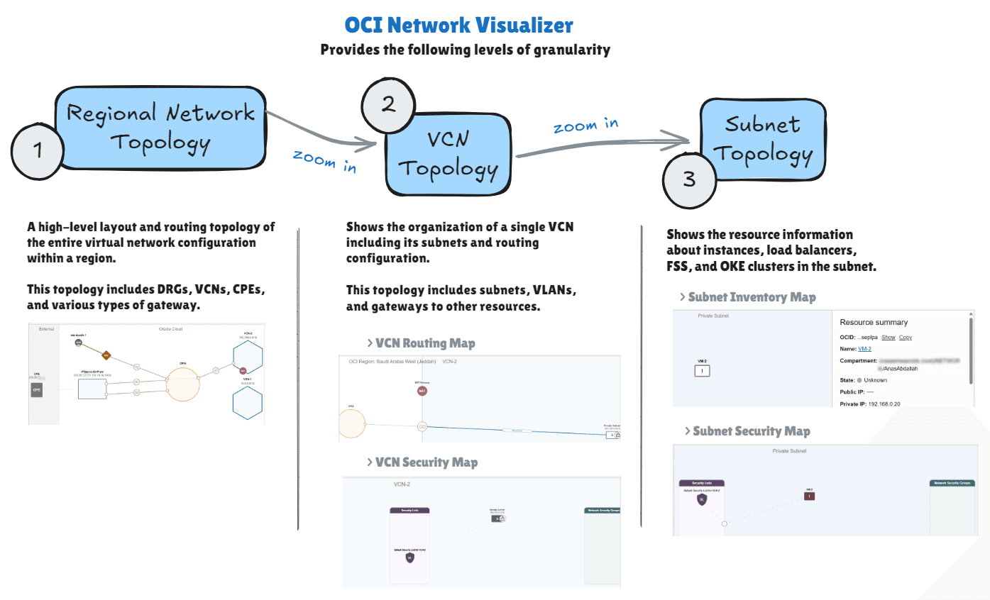
For this tutorial, we have summarized how the Network Visualizer works in the following diagram. For more information, see Network Visualizer.
Example
We will use the following architecture as our example.
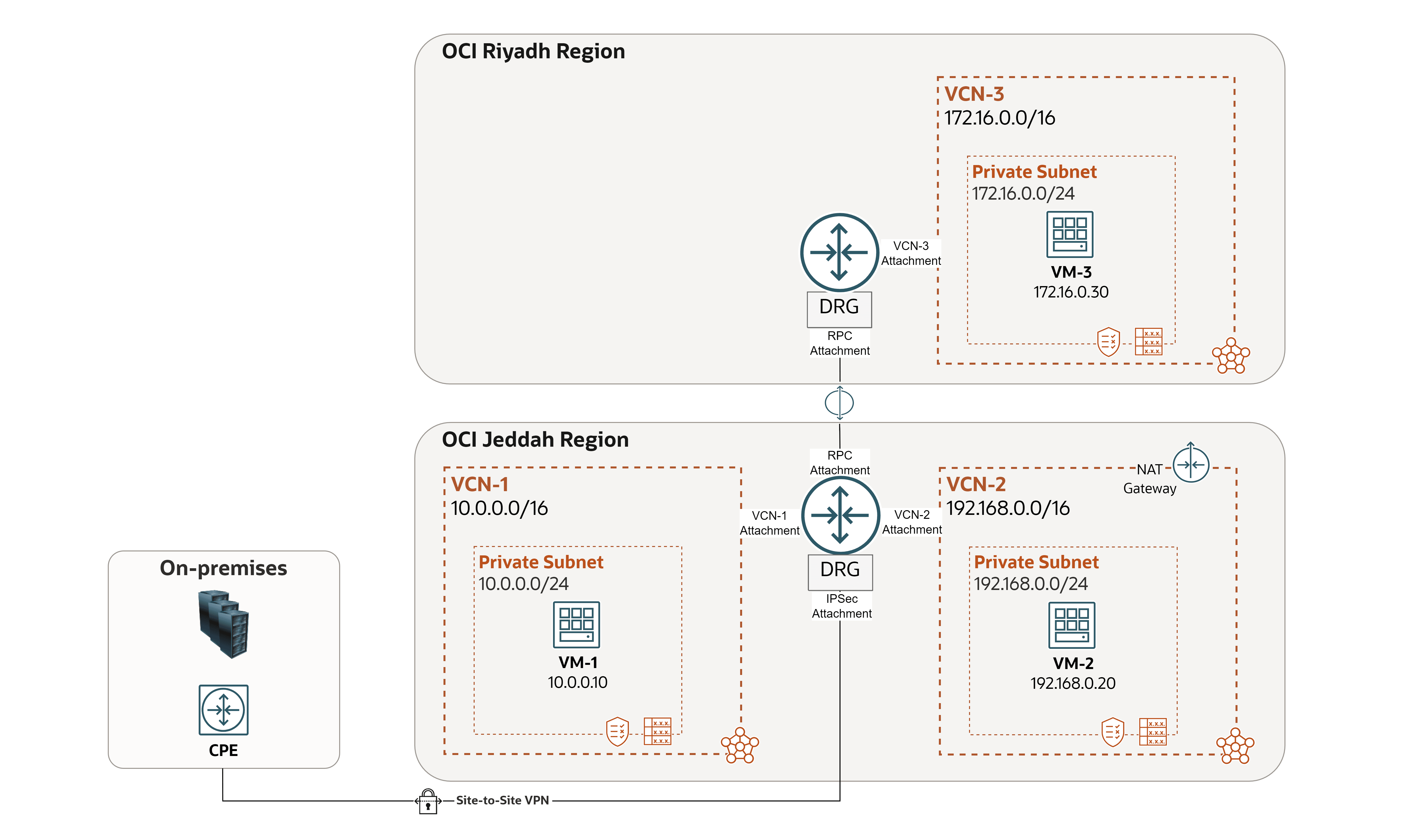
In this sample case, two issues came up in the environment. We will see how the Network Visualizer helps to identify and resolve them.
- Issue 1:
VM-1cannot pingVM-2. - Issue 2:
VM-2cannot reach the Internet.
Let us take a quick tour of our network environment using Network Visualizer in the OCI Console, which should reflect the architecture.
First Level: Regional Network Topology
This topology includes DRGs, VCNs, CPEs, and various types of gateways.
-
Log in to the OCI Console.
-
Make sure you are in the right region.
-
Click the hamburger menu (≡) from the upper left corner.
-
Click Networking.
-
Click Network visualizer.
-

-
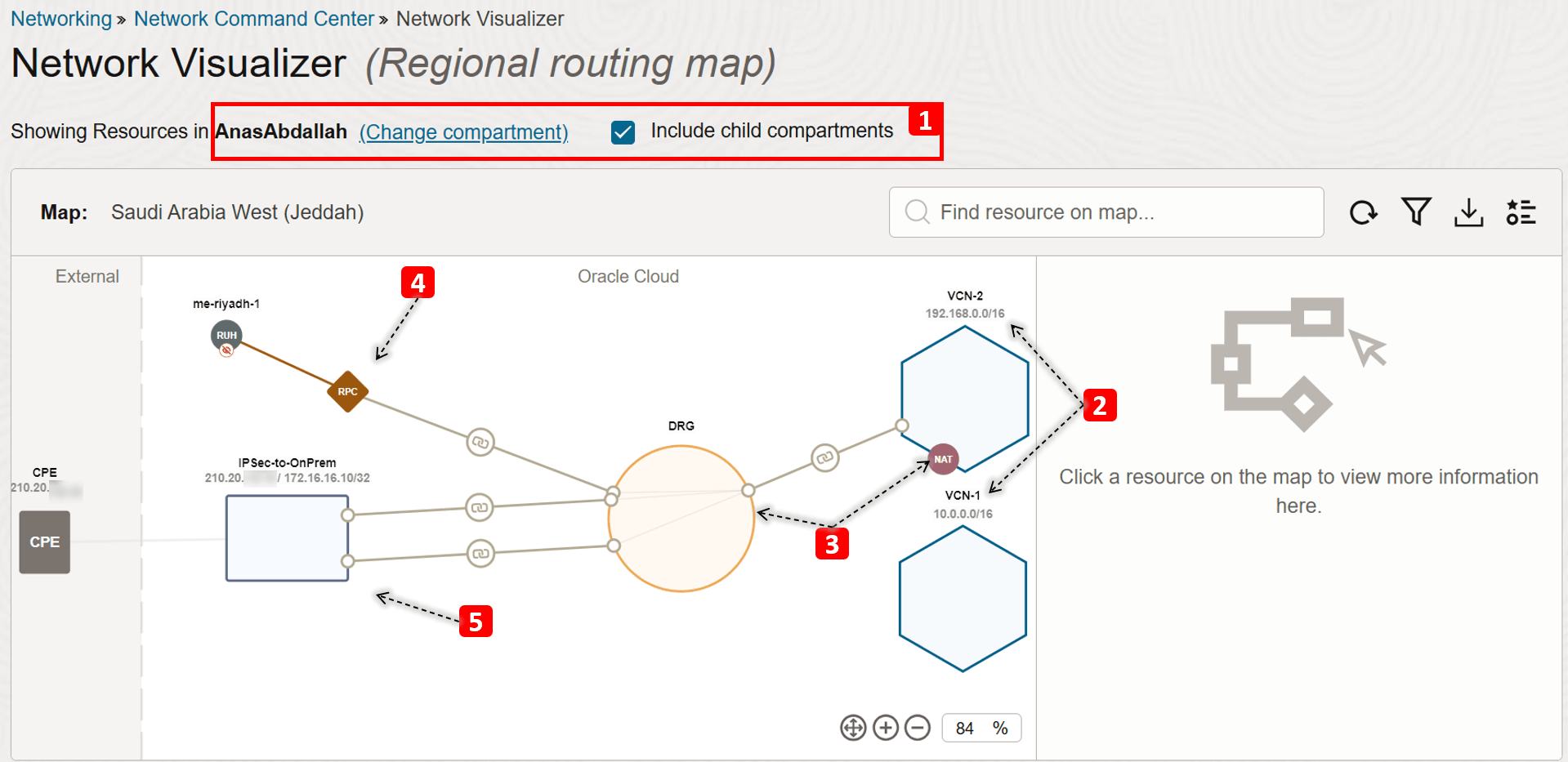
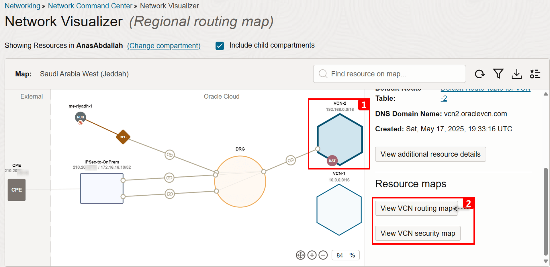
This is the first view you will see once you access Network Visualizer. Let us break it down.
- Select the compartment where your network components reside. If you are not sure where your resources are, select the parent compartment (or root compartment) and select Include child compartments.
- Note down the VCNs you have:
VCN-1andVCN-2, and the IPv4 address block for each. - Note the network gateways, such as:
- A DRG that has multiple attachments (VCNs, RPC, and IPSec).
- A NAT Gateway in
VCN-2.
- You will see a Remote Peering Connect (RPC) as well which connects the VCNs in Jeddah region to another region (Riyadh).
- There is also an IPSec connection to on-premises network. You can see the public IP of the customer’s CPE device (
210.20.x.x) and the on-premises network address block that will communicate privately with our VCNs (172.16.16.10/32).
-
Click
VCN-2. -
Now let us dig deeper into the VCN topology, starting with the routing map.
Second Level: VCN Topology
This topology includes subnets, VLANs, and gateways to other resources. In addition to the security rules that the subnet uses (security list or NSG).
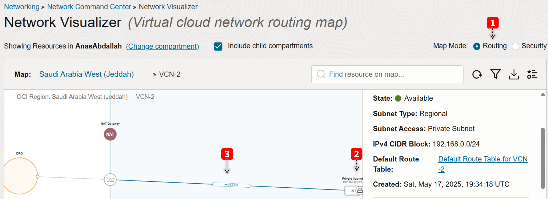
- We are in the VCN Routing map view.
VCN-2consists of one private subnet.- We can see a rule in the subnet’s route table that sends traffic destined to
VCN-1to the DRG as the next hop.
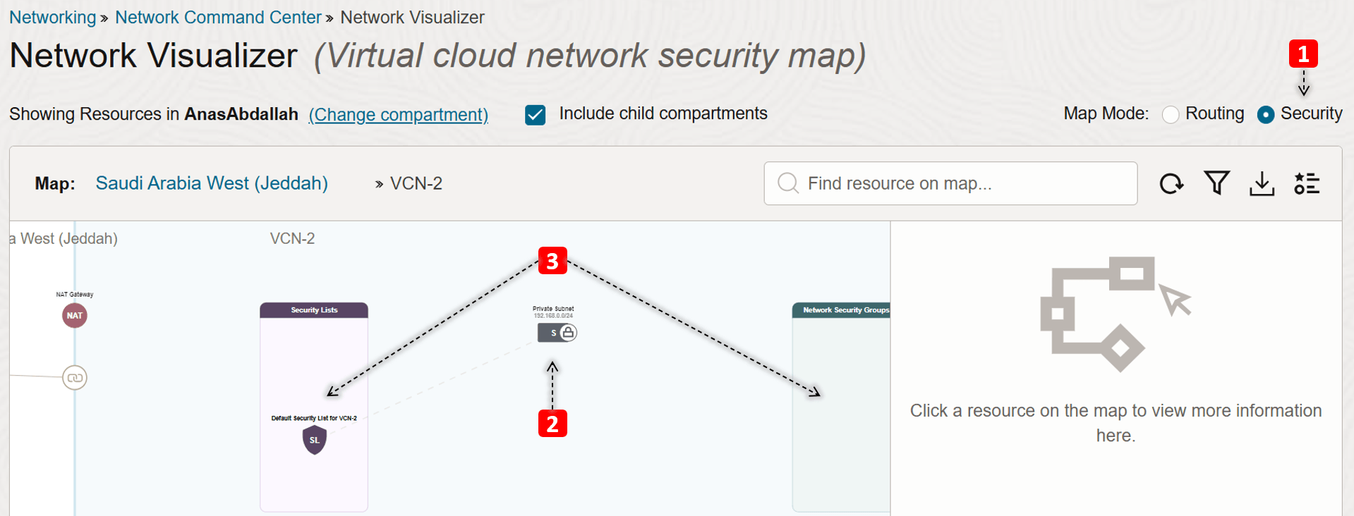
- Switch to the VCN Security map view.
- We can also see in this view that
VCN-2consists of one private subnet. - Also, security lists and Network Security Groups (NSGs) that are attached to the private subnet are visible in this mode.
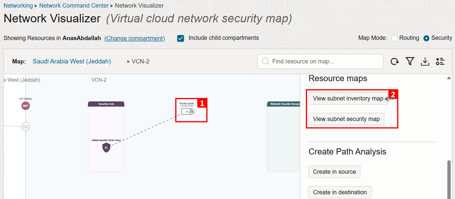
- Click the private subnet.
- Now let us dig deeper into the subnet topology, starting with the inventory map.
Third Level: Subnet Topology
This topology shows the resource information about OCI Compute instances, OCI Load Balancer(s), OCI File Storage Service, and OCI Kubernetes Engine (OKE) clusters in the subnet, and the security rules that the resource uses.
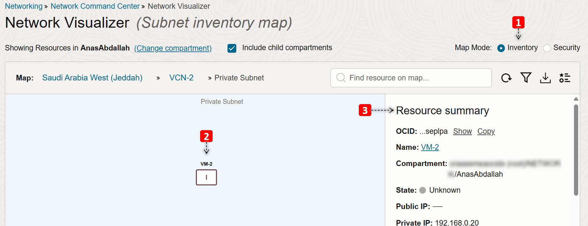
- We are in the subnet Inventory map view.
- We only have one compute instance in this subnet (
VM-2), click on it. - You can see some information about the VM like the compartment, IPs, and more.
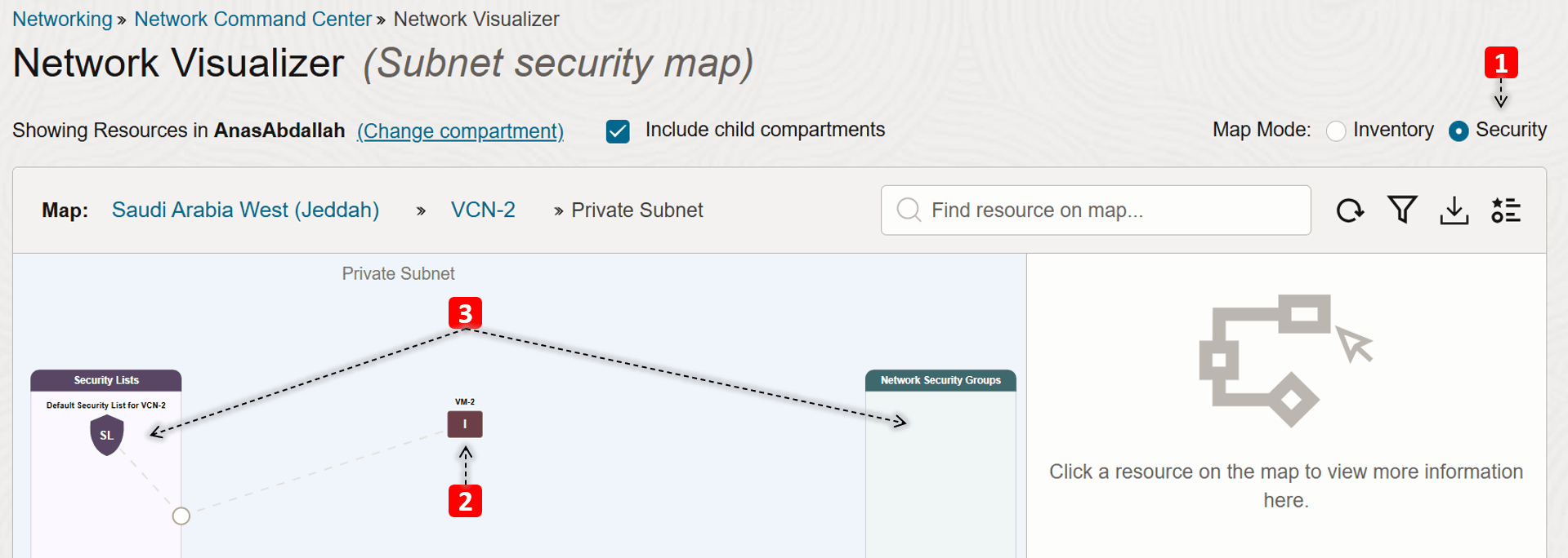
- Switch to the subnet Security map view.
- We only have one compute instance in this subnet (
VM-2). - We see which security lists and NSGs that
VM-2is using.
Summary:
We have explored how our network environment looks like and the components involved, what do you think are the root causes of the issue we mentioned earlier?
-
Issue 1:
VM-1cannot pingVM-2.In the First Level: Regional Network Topology, notice that
VCN-1is not attached to the DRG, so for the communication flow to happen betweenVM-1andVM-2, we must attachVCN-1and add the required route rule to enable the traffic flow.
Attaching
VCN-1and adding the following route rule (destination:VCN-2, next hop: DRG) should resolve the issue. That is assuming that routing inVCN-2is already configured properly, and ICMP type 8 is allowed in both of the security lists.
-
Issue 2:
VM-2cannot reach the Internet.In the Second Level: VCN topology, notice that the private subnet of
VCN-2has only one route to DRG, but no routes to the NAT gateway, which causesVM-2not having Internet connectivity.
Adding the following route rule (destination:
0.0.0.0/0, next hop: NAT Gateway) should resolve the issue. Assuming that egress traffic is already allowed in the security list.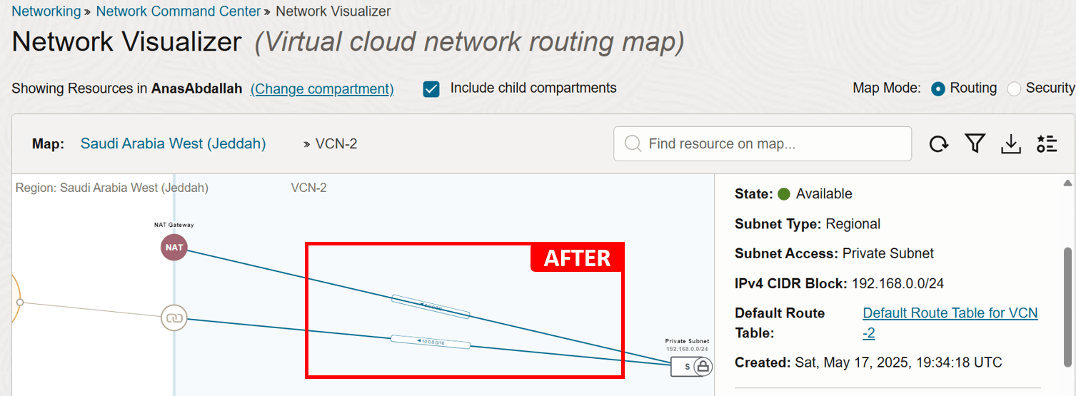
Network Visualizer can help you spot obvious issues caused by misconfigurations, as we saw in the example. But even when it does not reveal a clear problem, its real value lies in giving you a holistic view of your environment. That big-picture perspective helps you validate the current setup and gives you a solid starting point before digging deeper into more complex issues.
Task 2: Validate Network Configuration
After getting a clear view of your network environment and what components you have, the next essential step is to validate the actual configuration in place. Many connectivity issues come down to something simple; a missing route, overly strict security rules, or a subnet that is simply linked to the wrong route table or security list.
Before jumping into deeper troubleshooting like checking logs or running packet captures, it is important to ensure everything is configured as expected. This step can often reveal the root cause early and help you avoid unnecessary investigation later on.
Example
We will use the following architecture as our example.
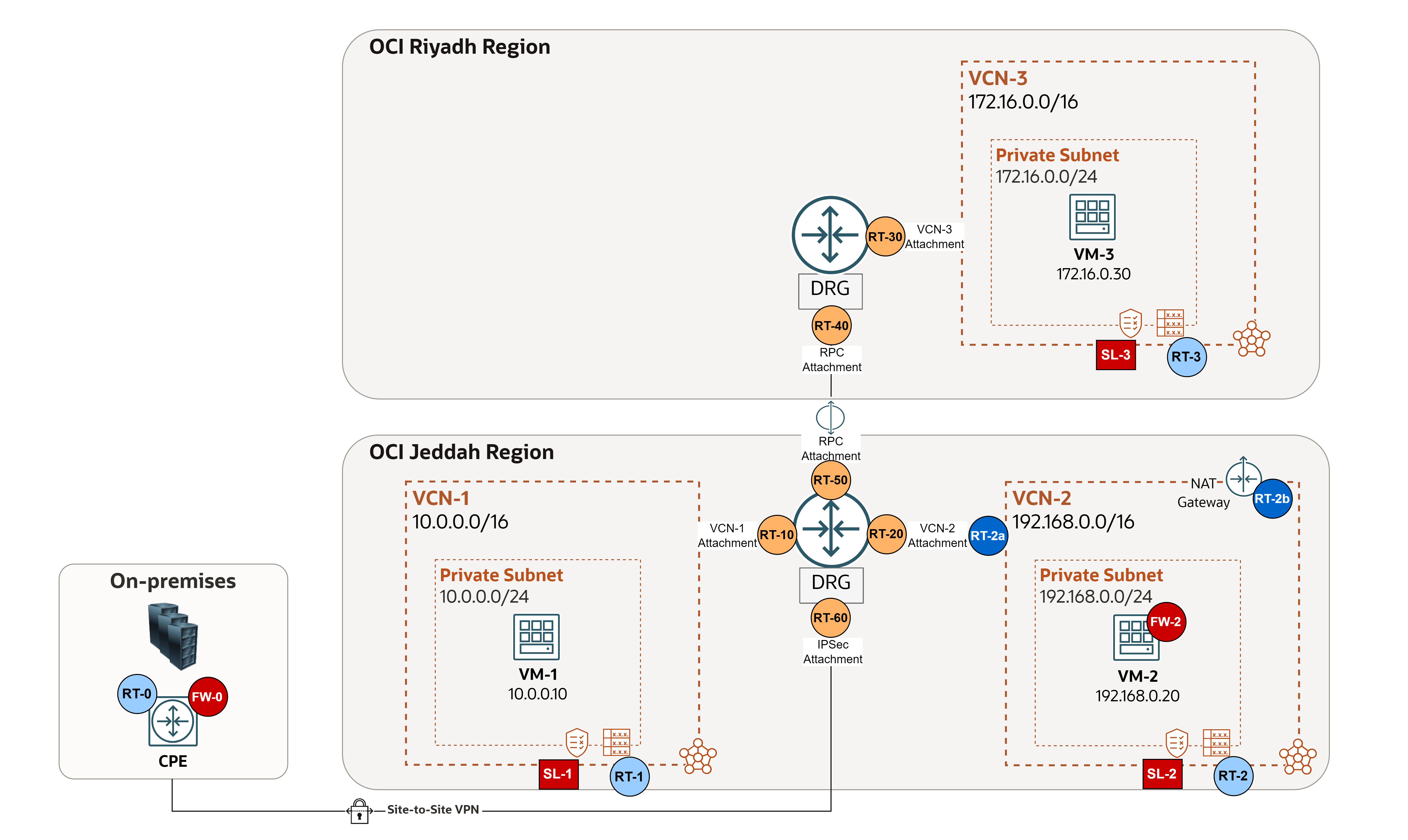
To begin with, let us outline the core routing and security components that play a central role in validating the configuration:
-
Routing Rules:
-
On-premises:
- RT-0: Routing of the on-premises Customer Premises Equipment (CPE) device (or multicloud), in case of FastConnect or IPSec connection (refer to the vendor: Cisco, Fortinet, and so on).
-
OCI VCN Route Tables: Exist in the VCN and used to send traffic out of the VCN (for example, to the internet, to an on-premises network, or to a peered VCN). These route tables have rules that look and act similar to traditional network route rules you might already be familiar with.
- RT-1-2-3: VCN routing tables that are assigned to the subnet level, in order to route outgoing traffic.
- RT-2a: VCN routing tables that are assigned to the DRG
VCN-2attachment, which is needed for transit routing scenarios, in this example, it is used as an Ingress Route Table to route traffic coming from DRG through the firewall for inspection. - RT-2b: VCN routing table that is attached to NAT gateway, in this example it is used as an Ingress Route Table to route response traffic coming back from the Internet to the firewall for inspection.
-
OCI DRG Route Tables: Exist in the DRG and used to route packets entering the DRG through the attachment.
- RT-10-20-30: DRG routing tables for VCN attachments, to route traffic coming from the VCN.
- RT-40-50: DRG routing tables for RPC attachments, to route traffic coming from the other region.
- RT-60: DRG RT for IPSec attachment, to route traffic coming from on-premises or a multicloud network.
-
-
Security Rules:
-
On-premises:
- FW-0: Control and restrict the traffic flow to and from OCI on the on-premises CPE device (or multicloud), in case of FastConnect or IPSec connection (refer to the vendor: Cisco, Fortinet, and so on).
-
OCI VCN Security Lists: Act as virtual firewalls for VCN-based resources, with ingress and egress rules that specify the types of traffic allowed in and out. Security lists are configured at the subnet level, which means that all VNICs in a subnet are subject to the same set of security lists.
- SL-1-2-3: Security lists that are assigned to the subnet level, in order to control ingress and egress traffic on each subnet.
Note: NSGs are another type of virtual firewalls available in OCI. They function similarly to security lists but offer more granular control, as they are applied at the resource level. This is useful when two resources in the same subnet require different security postures. However, NSGs are not used in this tutorial. For more information, see Comparison of Security Lists and Network Security Groups.
-
OCI Network Firewall or a Third-Party Firewall: Acts as a centralized, stateful inspection point for traffic between subnets, VCNs, and external networks, enforcing advanced security policies beyond basic security list rules.
- FW-2: Controls and inspects all North-South and East-West traffic in an OCI network environment.
-
We understand how routing and security are applied across the environment, let us take a closer look at the following sample case, where four issues have come up. By applying some common sense, we will figure out which configurations to check, and where, for each troubleshooting scenario.
Note:
- If NSGs are used, review the configurations applied to each VNIC attached to every VM.
- In this example,
VM-2acts as a third-party firewall (FortiGate). It is already configured to route traffic properly.
-
Issue 1:
VM-1cannot pingVM-3(different regions, firewall should NOT inspect the traffic).- Routing:
- Request: RT-1 > RT-10 > RT-40.
- Response: RT-3 > RT-30 > RT-50.
- Security: ICMP type 8 should be allowed to have a successful ping.
- Request: SL-1 (Egress Rules) > SL-3 (Ingress Rules).
- Response: SL-3 (Egress Rules) > SL-1 (Ingress Rules).
- Routing:
-
Issue 2:
VM-1cannot reach the Internet (VM-2firewall should inspect the traffic).- Routing:
- Request: RT-1 > RT-10 > RT-2a > FW-2 internal routing > RT-2.
- Response: RT-2b > FW-2 routing > RT-2 > RT-20.
- Security:
- Request: SL-1 (Egress Rules) > SL-2 (Ingress & Egress Rules) > FW-2 (Ingress & Egress Rules).
- Response: SL-2 (Ingress & Egress Rules) > FW-2 (Ingress & Egress Rules) > SL-1 (Ingress Rules).
- Routing:
-
Issue 3:
VM2cannot reach the Internet.- Routing:
- Request: RT-2.
- Response: No routing is required.
- Security:
- Request: SL-2 (Egress Rules).
- Response: SL-2 (Ingress Rules).
- Routing:
-
Issue 4: On-premises cannot ping
VM-1(firewall should inspect the traffic).- Routing:
- Request: RT-0 (on-premises CPE) > RT-60 > RT-2a > FW-2 internal routing > RT-2 > RT-20.
- Response: RT-1 > RT-10 > RT-2a > FW-2 internal routing > RT-2 > RT-20.
- Security:
- Request: FW-0 (Egress Rules) > SL-2 (Ingress & Egress Rules) > FW-2 (Ingress & Egress Rules) > SL-1 (Ingress Rules).
- Response: SL-1 (Egress Rules) > SL-2 (Ingress & Egress Rules) > FW-2 (Ingress & Egress Rules) > FW-0 (Ingress Rules).
- Routing:
It is crucial to understand how traffic is managed and controlled throughout the network. By tracking the path traffic should take, you can quickly identify where problems might occur and which settings need to be reviewed when troubleshooting.
Task 3: Utilize Network Path Analyzer
You reviewed the overall network setup, manually checked the configuration of routing and security rules. However, the issue persists, maybe you overlooked some configuration detail, so what is the next step?
This is where Network Path Analyzer comes in. Think of it as your virtual network detective, designed to inspect your OCI network routing and security configuration in real-time. It collects and analyzes them to determine how the paths between the source and the destination will function or fail. No actual traffic is sent, instead, the configuration is examined and used to confirm reachability.
Instead of performing manual connectivity tests like ping or telnet from individual VMs or databases, Network Path Analyzer lets you verify the configuration of communication paths directly within the OCI Console, offering a more efficient and centralized troubleshooting approach.
Network Path Analyzer supports the following scenarios:
- OCI to OCI.
- OCI to on-premises.
- On-premises to OCI.
- Internet to OCI.
- OCI to internet.
Example 1
We will use the following architecture as our example.
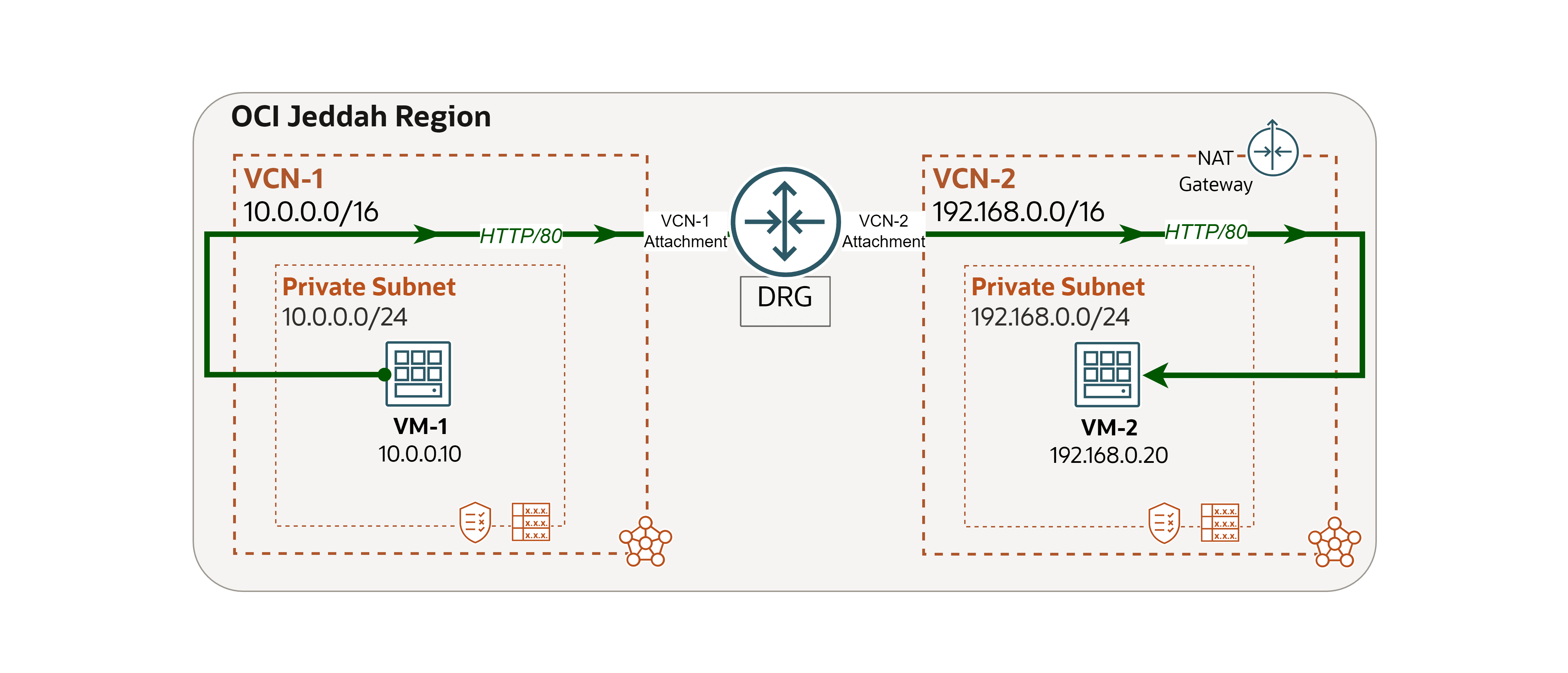
We encountered a network issue and we will use Network Path Analyzer to trace and address the root cause.
Issue: VM-1 cannot access a website hosted on VM-2 (OCI to OCI).
-
Log in to the OCI Console, go to
VM-2and run the following command to check if the website is running locally.curl localhost
-
Go to the OCI Console, navigate to
VM-1and run the same command to test connectivity toVM-2.curl 192.168.0.20You will see that the request fails. In the next steps, we will use Network Path Analyzer to investigate the cause.

-
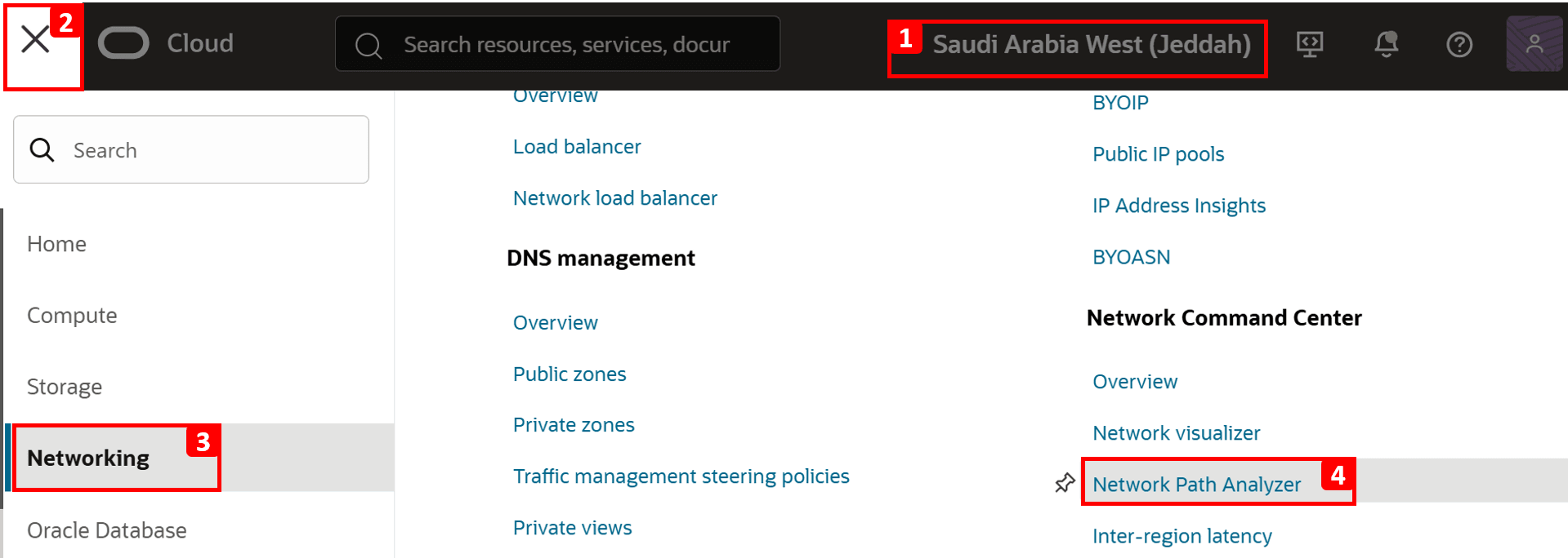
Go to the OCI Console.
- Make sure you are in the right region.
- Click the hamburger menu (≡) from the upper left corner.
- Click Networking.
- Click Network Path Analyzer.
-
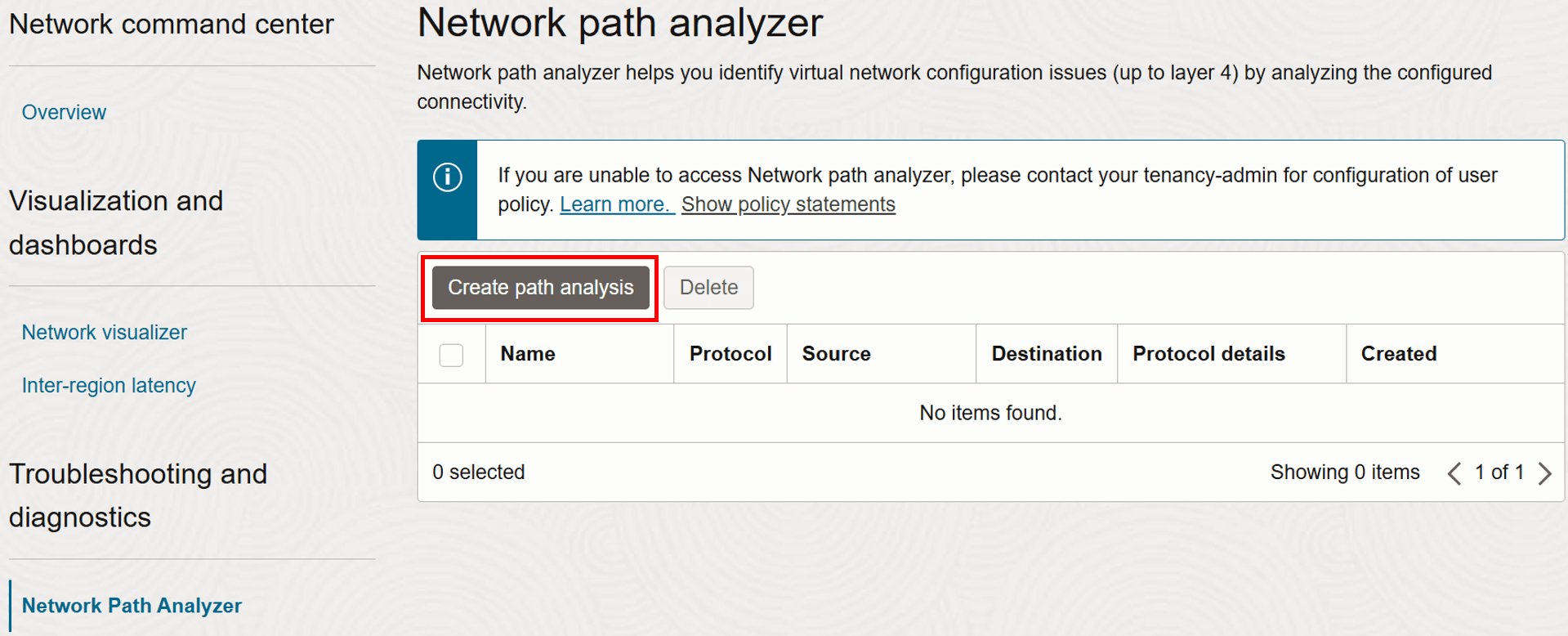
Click Create path analysis.
-
Now, let us configure the details of the network flow to be tested.
- Enter Name as
test-vm1-to-vm2-port80. - Select Protocol as TCP.

- Enter Name as
-
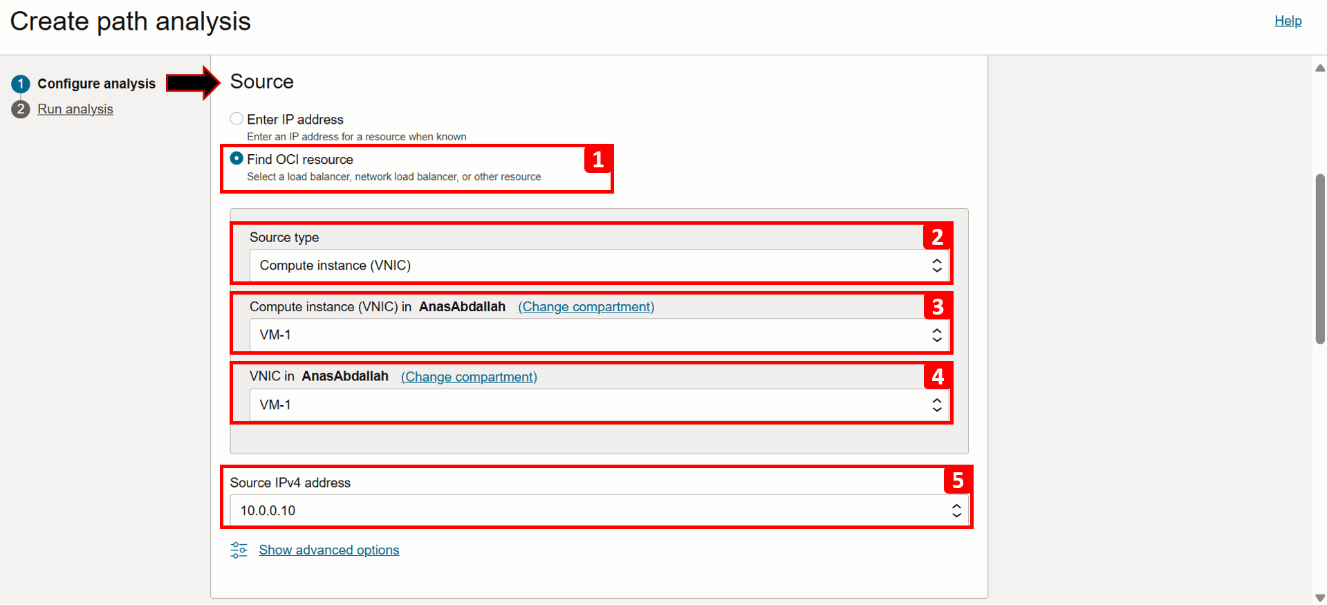
We will start with filling the source information, which in this case is
VM-1.- Select Find OCI resource.
- Select Source type as Compute instance (VNIC).
- Select
VM-1from the list. - Select VNIC that will generate the traffic (this is already auto-filled if the VM has only one VNIC).
- Select Source IPv4 address
10.0.0.10(this is also auto-filled if there is only one IPv4 address).
- Click Show advanced options.
- Here, you can specify the source port if needed; for this example, leave it set to Use any port.

-
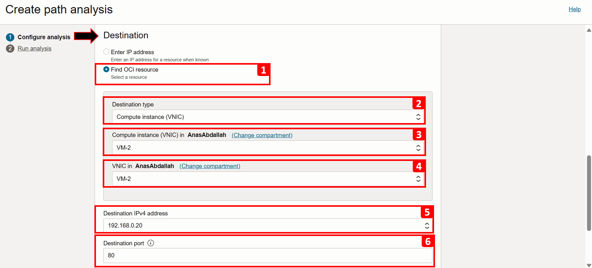
Next, we will fill the destination information, which in this case is
VM-2.- Select Find OCI resource.
- Select Source type as Compute instance (VNIC).
- Select VM-2 from the list.
- Select VNIC that will generate the traffic (this is already auto-filled if the VM has only one VNIC).
- Select Source IPv4 address as
192.168.0.20(this is also auto-filled if there is only one IPv4 address). - Enter Destination port as 80.
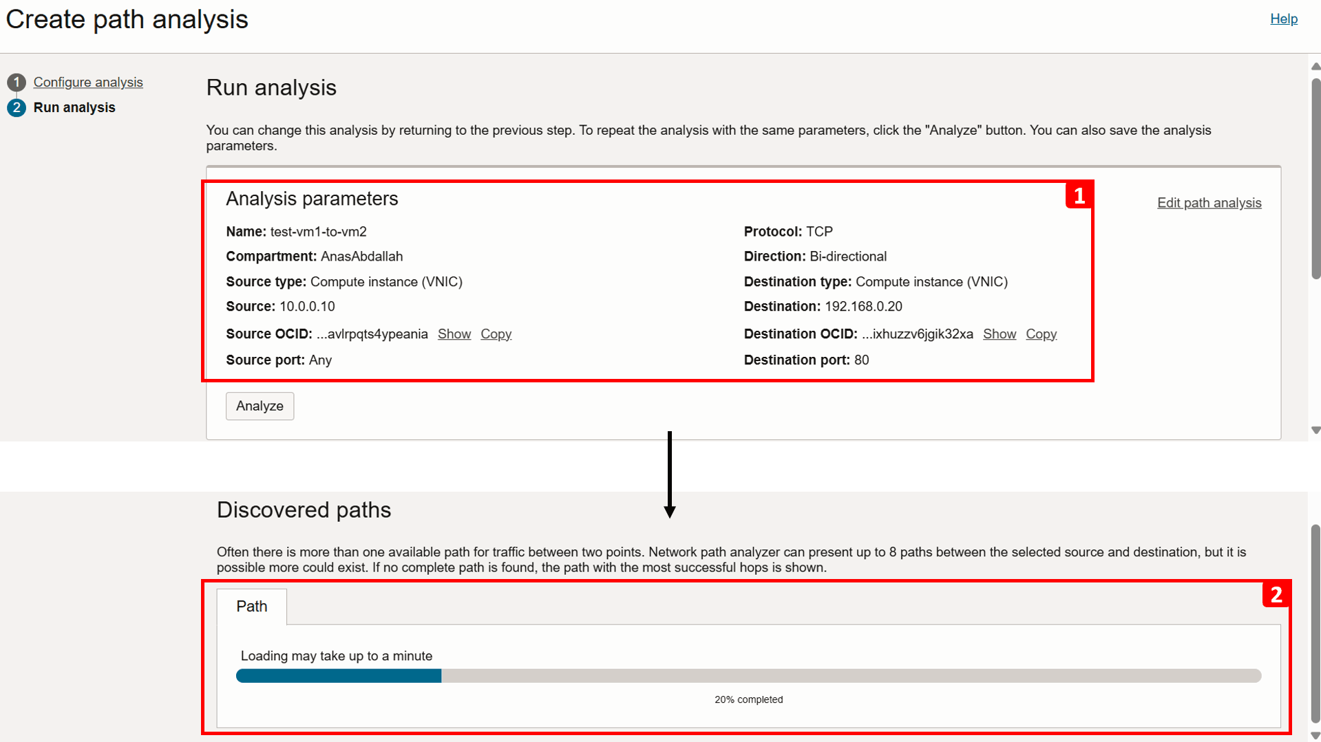
- To analyze both forward and reverse traffic, keep the Direction as Bi-directional.
- Click Run analysis.

- The connection details are displayed as the analysis runs.
- Scroll down to track the progress of the analysis and wait until it finishes, this can take a minute or two.
-
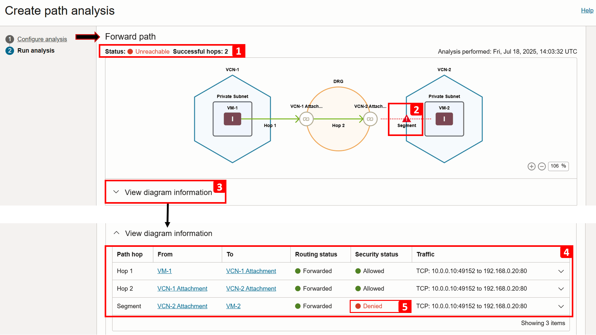
Analysis is complete. Let us start checking the Forward path result.
- The analysis indicates
VM-2is unreachable following two successful hops. - The drop occurs between the DRG and
VM-2. - For more information, click View diagram information.
- This table breaks down the routing flow and security checks at each step in the path.
- If you zoom in, you will see that traffic is being Denied between the DRG and
VM-2.
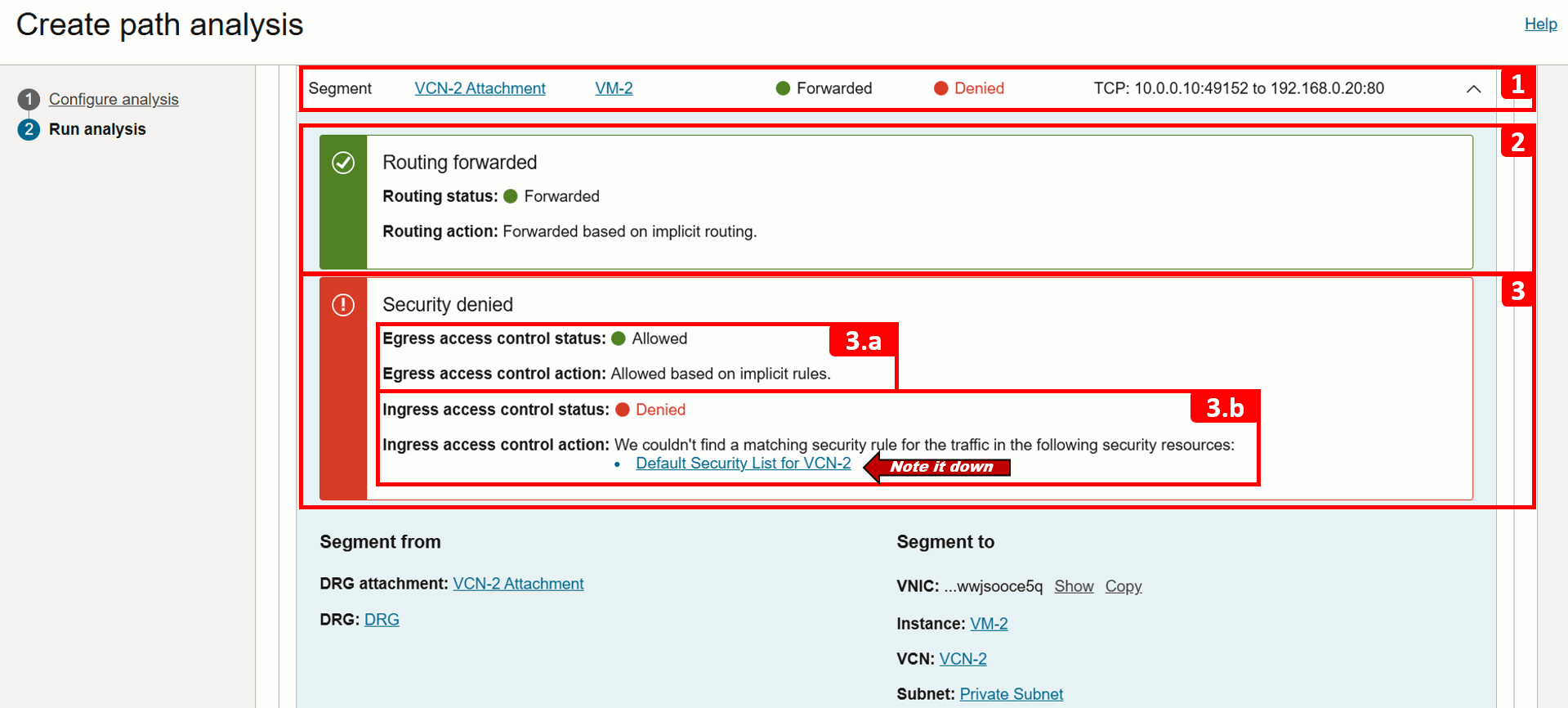
- Expand the same segment for more detail.
- Note that Routing is forwarded successfully.
- However, the traffic is being denied due to a missing security rule:
- (3.a) Egress traffic is allowed, no issues here.
- (3.b) Ingress traffic is denied because there is no rule permitting it. The security list associated with the
VM-2subnet is shown (Default Security List for VCN-2), make a note of it, as we will review it in the next steps. At this point, we have identified the source of the problem.
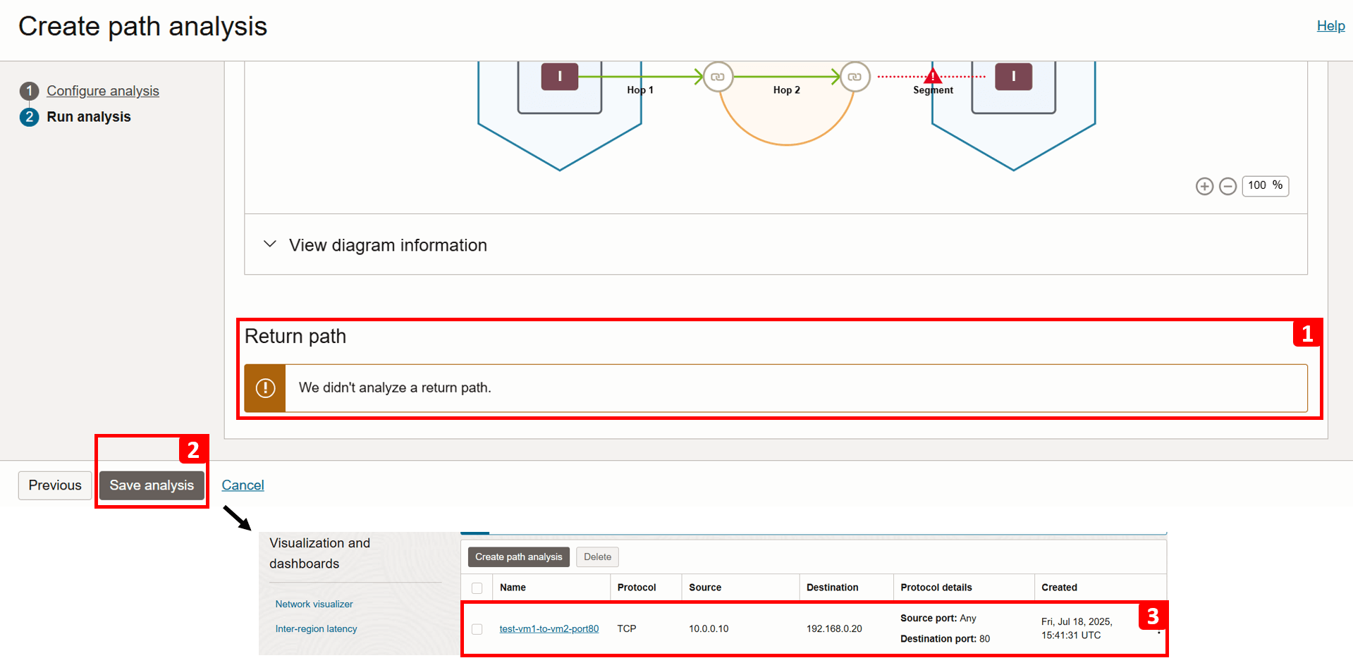
- The return path is not analyzed because the forward path check failed.
- Click Save analysis.
- You can revisit and rerun the analysis anytime. We will run it again later in this tutorial after fixing the issue.
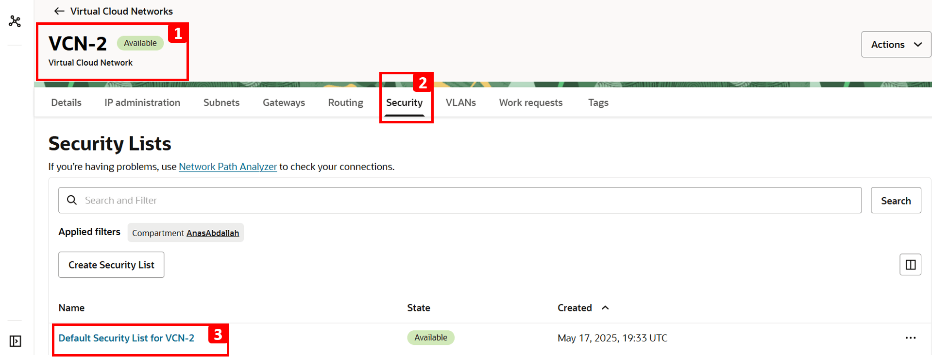
- Navigate to
VCN-2, where the destination VM is located. - Click Security.
- Click Default Security List for
VCN-2.
Note: Security lists operate at the subnet level, meaning any traffic allowed by these rules applies to all VNICs within that subnet.
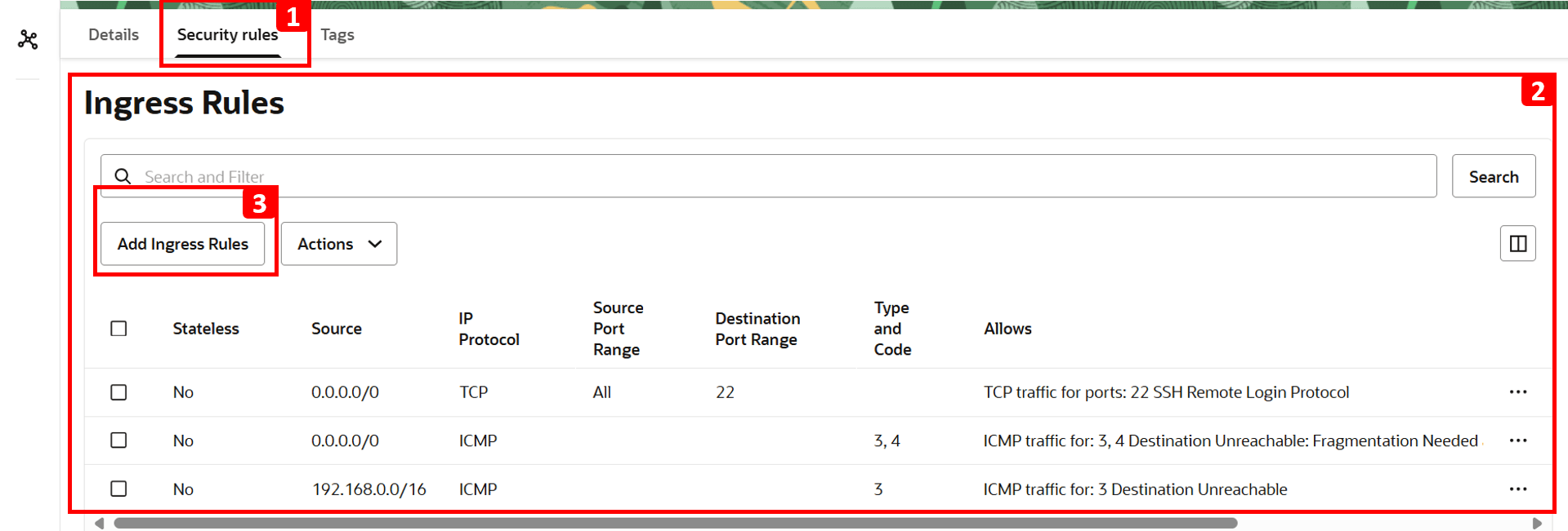
- Click Security rules.
- The table shows which traffic is allowed. Everything else including HTTP is denied by default since there is no rule to allow it. That is why
VM-1cannot access the website hosted onVM-2. - To fix this, click Add Ingress Rules.
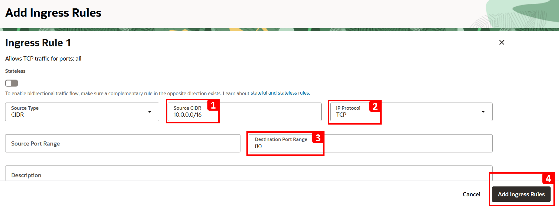
- Enter
10.0.0.0/16in the Source CIDR field (this is the CIDR forVCN-1). - Select TCP for the IP Protocol.
- Set 80 as Destination Port.
- Click Add Ingress Rules.
- The analysis indicates
-
Log in to
VM-1and run the same command to test connectivity toVM-2.curl 192.168.0.20You should now see that the website is reachable.

-
Go back to the analysis to perform another run and verify that the issue is fixed.

-
Click Analyze.

-
Wait for the analysis to finish.

-
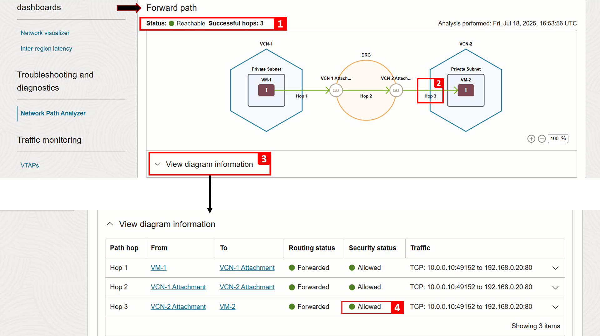
Analysis is complete. Let us check the Forward path result.
- The status now shows Reachable.
- Hop 3 is now successful because we added a security rule allowing HTTP traffic.
- Click View diagram information.
- You can see that the security status for hop 3 is now Allowed (previously, it was Denied).
-
Verifying the return path, we can see it is successful as well.

Example 2
We will use the following architecture as our example.
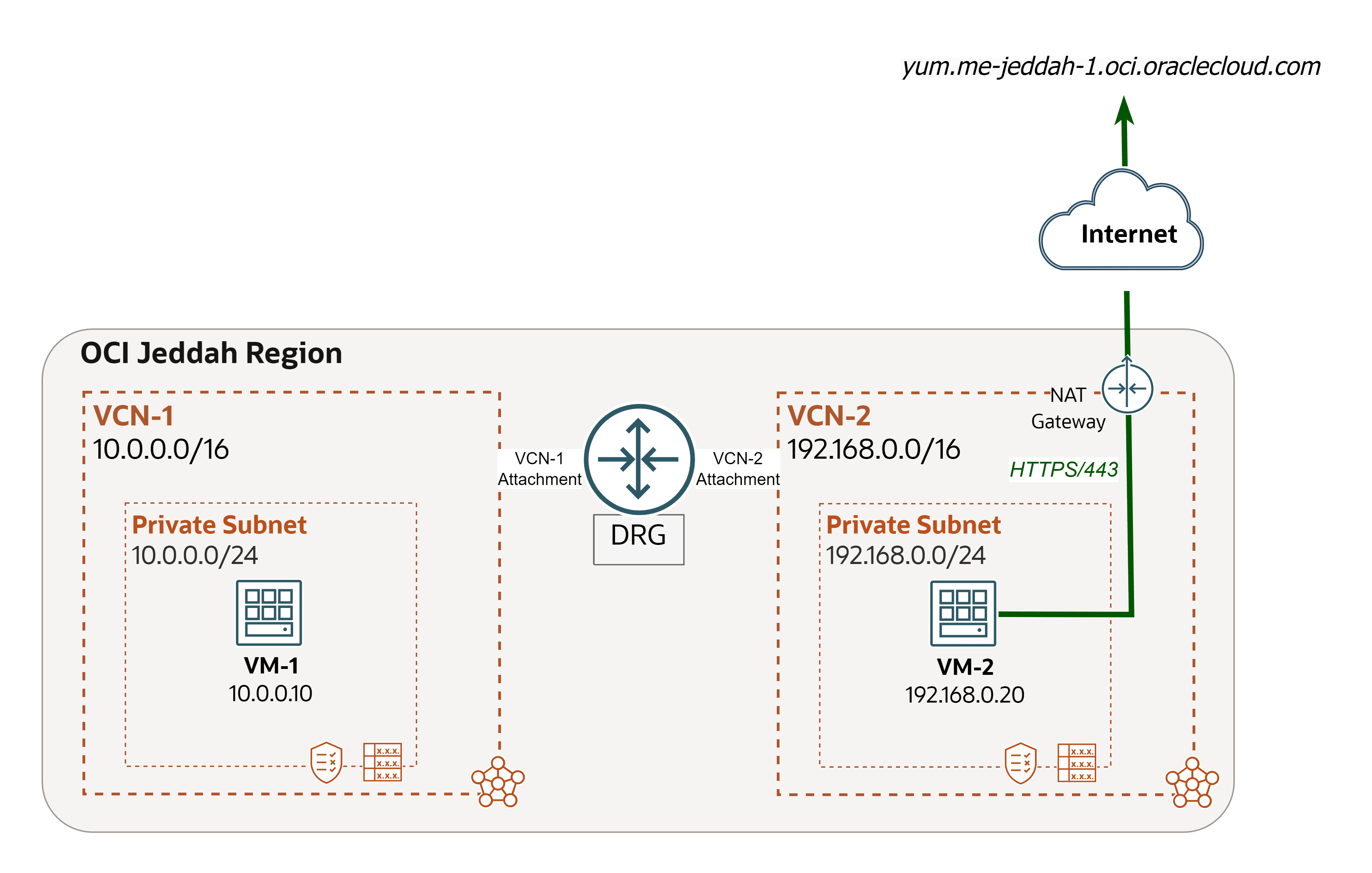
We encountered a network issue and we will use Network Path Analyzer to trace and address the root cause.
Issue: VM-2 cannot install telnet package (OCI to Internet).
Note: Telnet is a network protocol and a command-line tool used to remotely access and manage devices over a network. It is used for basic network testing as well (for example, checking if a port is open).
-
Check if we can install
telnetonVM-2.-
Log in to
VM-2and run the following command to installtelnet.sudo yum install telnet -
Enter
yand press Enter to continue. -
The installation failed.
VM-2attempted to connect to the regional YUM repository (yum.me-jeddah-1.oci.oraclecloud.com) but was unable to reach it.

-
Run the command below to find the IP of the
yumrepository.dig yum.me-jeddah-1.oci.oraclecloud.com -
Write down the IP addresses.
VM-2cannot reach these public IPs, which indicates it does not have internet access through a NAT gateway or private access to Oracle Services Network through a service gateway to reach theyumrepository, or the outgoing traffic is being blocked. To get to the bottom of the issue, we are going to move forward with the NPA analysis in the next steps.

-
-
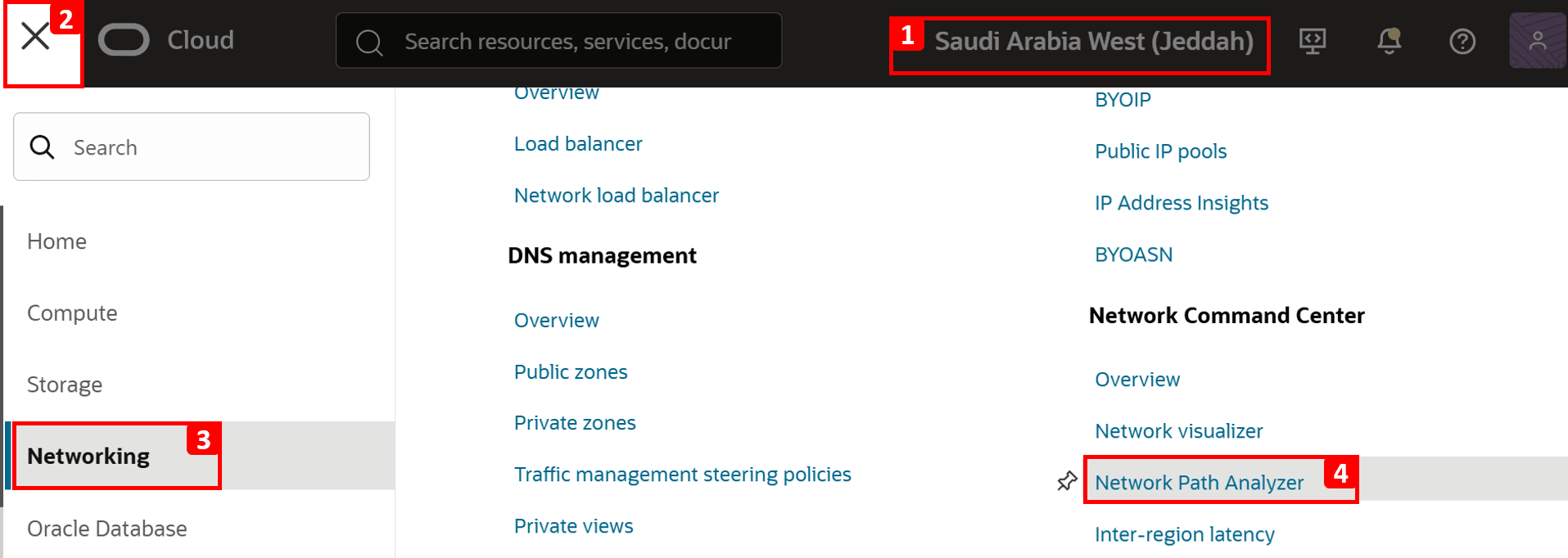
Go to the OCI Console.
- Make sure you are in the right region.
- Click the hamburger menu (≡) from the upper left corner.
- Click Networking.
- Click Network Path Analyzer.
-
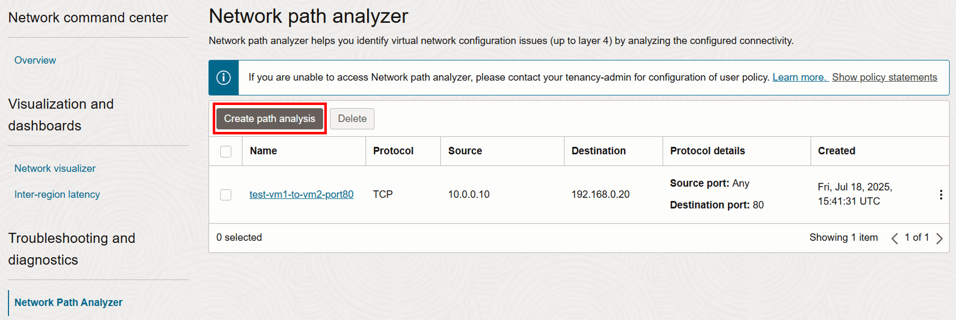
Click Create path analysis.
-
Now, let us configure the details of the network flow to be tested.
- Enter Name as
test-vm2-to-internet-port443. - Select Protocol as TCP.

- Enter Name as
-
We will start with filling the source information, which in this case is
VM-2.- Select Find OCI resource.
- Select Source type as Compute instance (VNIC).
- Select
VM-2from the list. - Select VNIC that will generate the traffic (this is already auto-filled if the VM has only one VNIC).
- Select Source IPv4 address as
192.168.0.20(this is also auto-filled if there is only one IPv4 address).
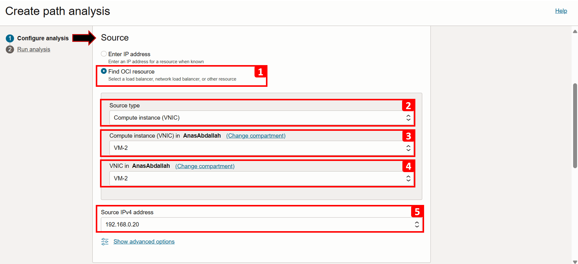
- Click Show advanced options.
- Here, you can specify the source port if needed; for this example, leave it set to Use any port.

-
Next, we will fill the destination information, which in this case is the internet, specifically, the public IPs of the
yumrepository (192.29.119.92and192.29.125.93), we will test using only one of them.- Select Enter IP address.
- Enter the Destination IPv4 address
192.29.119.92. - Enter the Destination port as 443, since access to the repository is over HTTPS.

- To analyze both forward and reverse traffic, keep the Direction as Bi-directional.
- Click Run analysis.

- The connection details are displayed as the analysis runs.
- Scroll down to track the progress of the analysis and wait until it finishes, this can take a minute or two.
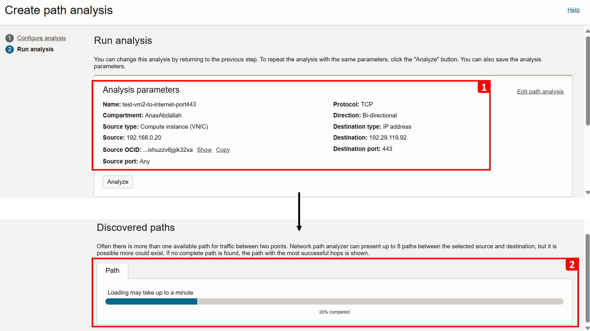
-
Analysis is complete. Let us start checking the Forward path result.
- The analysis shows that
VM-2is unable to reach the internet. - This segment highlights a missing configuration that prevents traffic from exiting
VCN-2. - For more information, click View diagram information.
- This table breaks down the routing flow and security checks at each step in the path. As noticed, the flow is direct as there are no intermediate hops in between.
- If you zoom in, you will see that there is No route defined for this traffic.
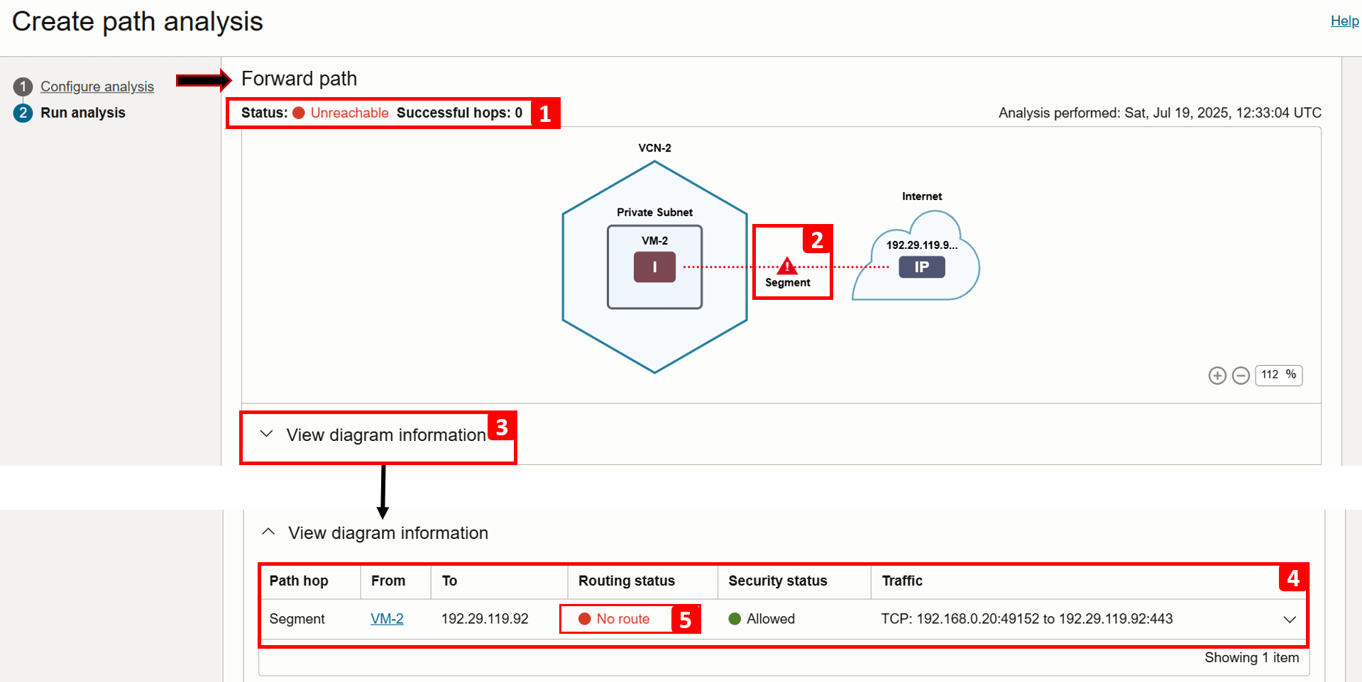
- Expand the same segment for more information.
- There is no routing configured to send traffic over the internet, to fix that, we need to add a rule to the
VM-2subnet route table (Default Route Table for VCN-2), make a note of it, as we will review it in the next tasks. At this point, we have identified the source of the problem. - Note that security is Allowed.
- (3.a) Egress traffic is allowed, no issues here.
- (3.b) Ingress traffic is not relevant in this case, as the scenario focuses only on outbound traffic.
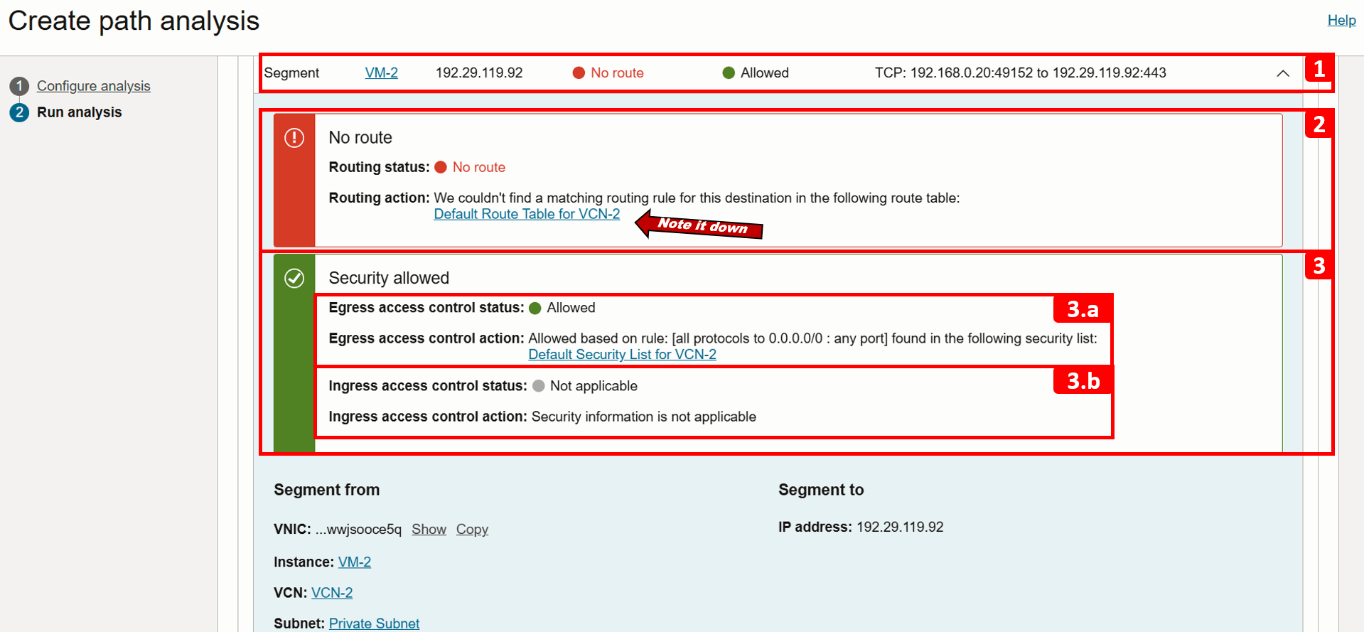
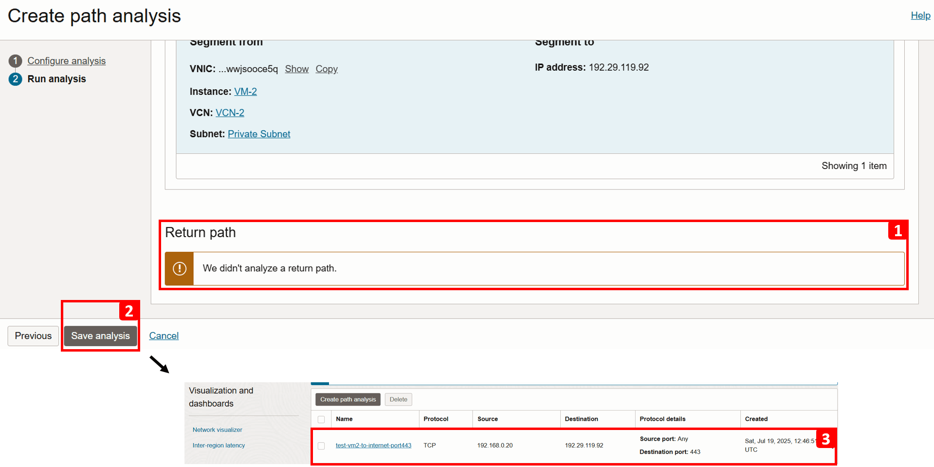
- The return path is not analyzed because the forward path check failed.
- Click Save analysis.
- You can revisit and rerun the analysis anytime. We will run it again later in this tutorial after fixing the issue.
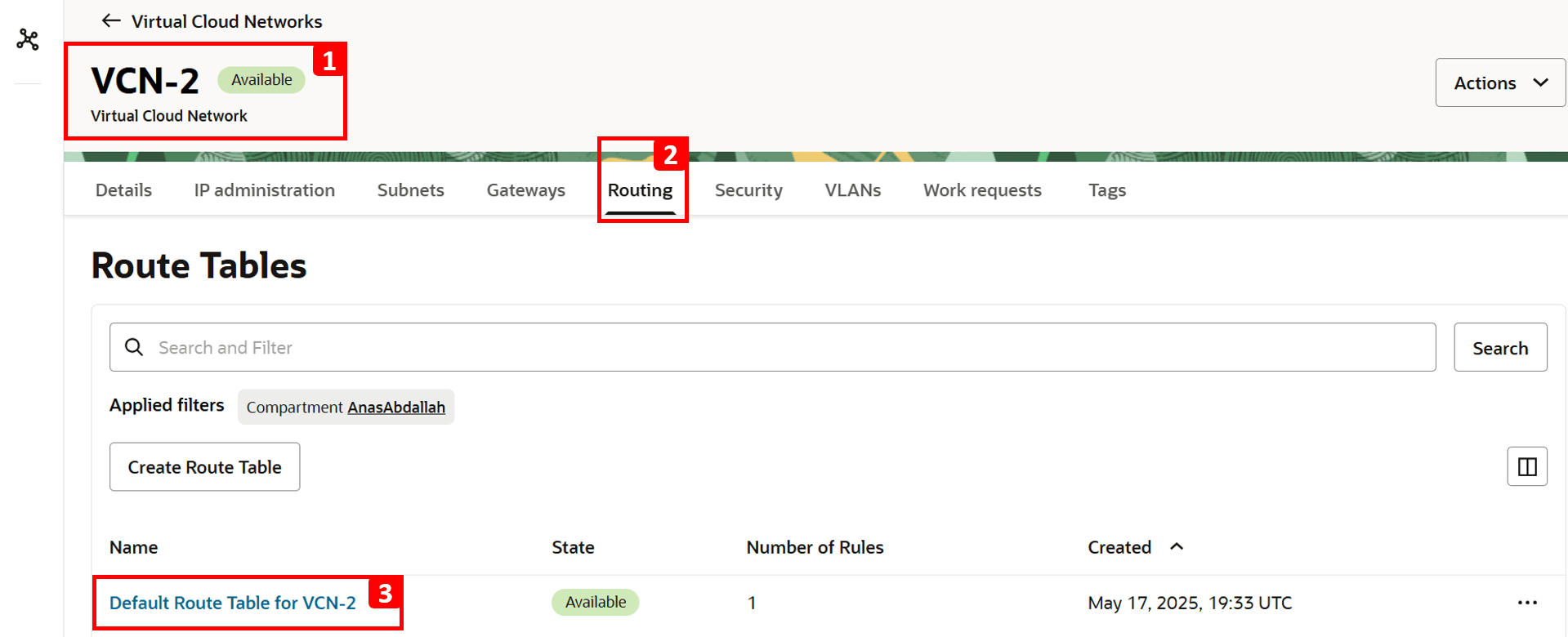
- Navigate to VCN-2, where the source VM is located.
- Click Routing.
- Click Default Route Table for VCN-2.
Note: Route tables operate at the subnet level, meaning any rules defined in the table apply to all resources within that subnet. Route tables can also be associated with specific VNICs or IP addresses as well using Per-Resource Routing. However, this is not relevant to our tutorial. For more information, see Per-resource Routing.
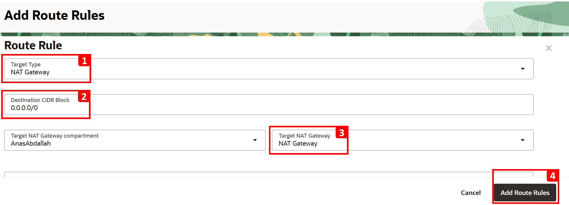
- Click Route Rules.
- Currently, there is only one route rule configured, to route traffic to
VCN-1. - To enable internet access, click Add Route Rules.

- Select NAT Gateway as Target Type.
- Enter
0.0.0.0/0as Destination CIDR Block. - Select NAT Gateway created earlier.
- Click Add Route Rules.
- The analysis shows that
-
Log in to
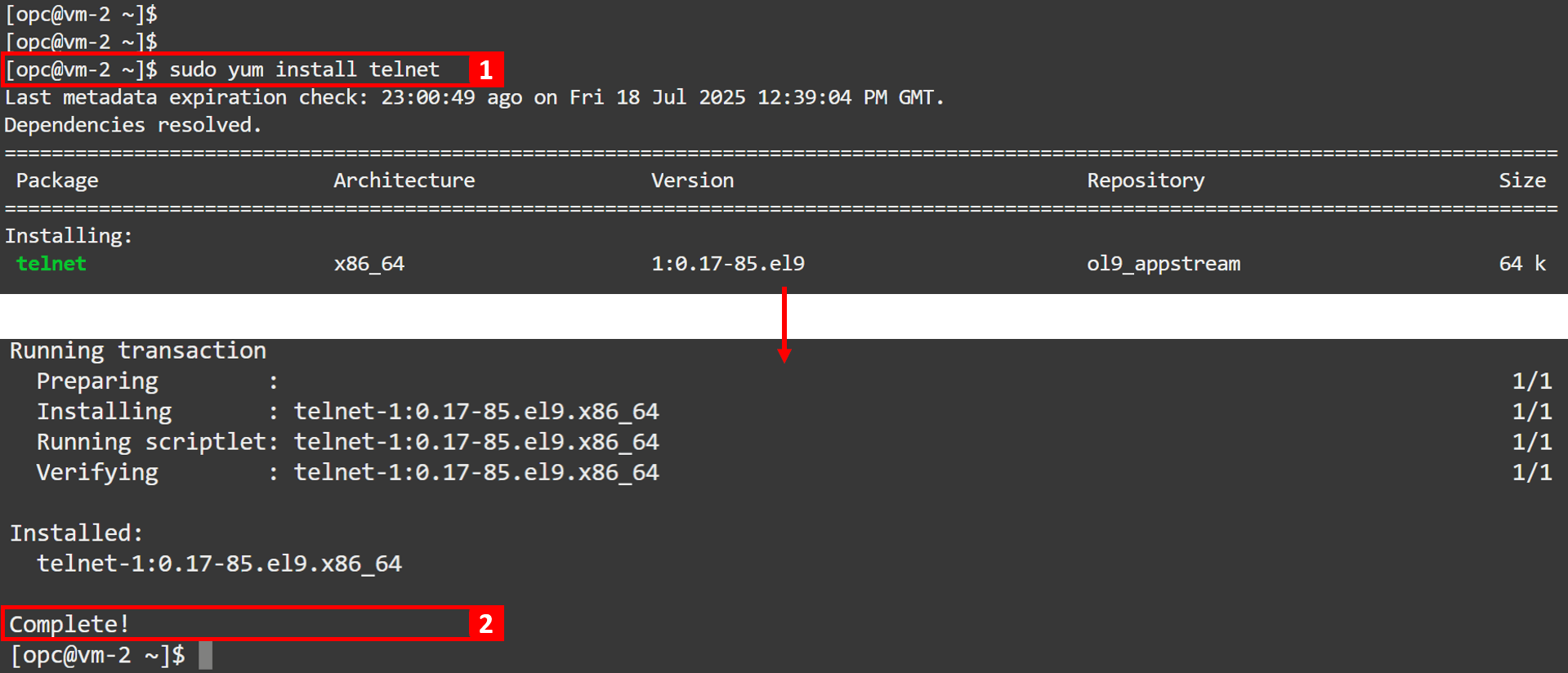
VM-2and try to installtelnetagain.-
Run the following command.
sudo yum install telnet -
Installation is Complete!.
-
-
Go back to the analysis to perform another run and verify that the issue is fixed.

-
Click Analyze.

-
Wait for the analysis to finish.

-
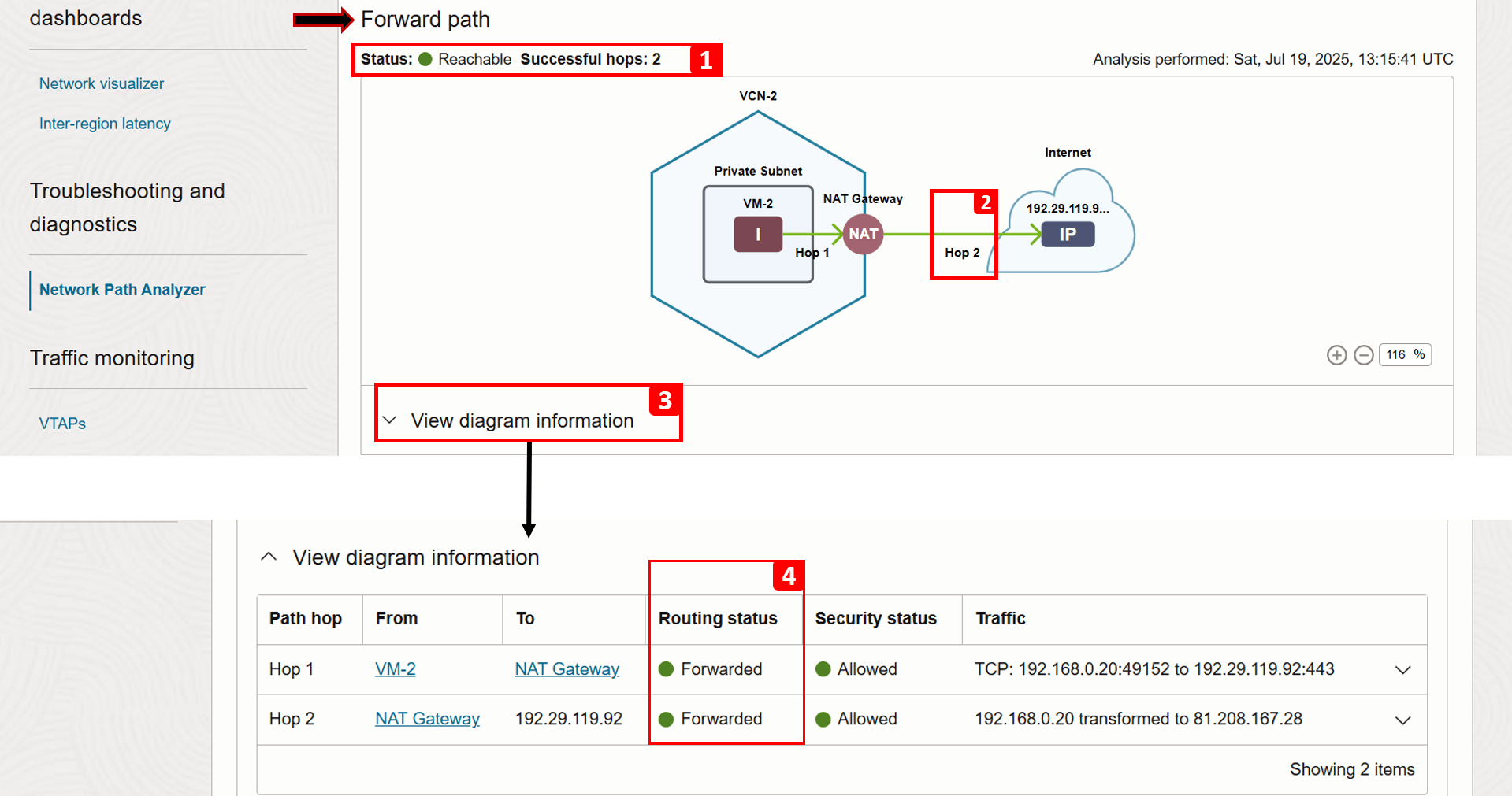
Analysis is complete. Let us check the Forward path result.
- The status now shows Reachable.
- Hop 2 is now successful because we added a route rule sending traffic to the NAT gateway.
- Click View diagram information.
- You can see that the routing status for hop 2 is now Forwarded (previously, it was No route).
-
Verifying the return path, we can see it is successful as well.

Task 4: Analyze VCN Flow Logs
VCN Flow Logs offer an additional layer of visibility into traffic behavior. This service allows you to drill-down into the actual traffic hitting each VNIC, indicating whether it was accepted or rejected based on security list and NSG rules, helping you troubleshoot security-related issues.
Beyond troubleshooting, VCN Flow Logs are crucial for monitoring network activity, capturing source/destination IPs, ports, protocols, and timestamps, providing the detailed telemetry needed for audits and security investigations as well.
Example
We will use the following architecture as our example.
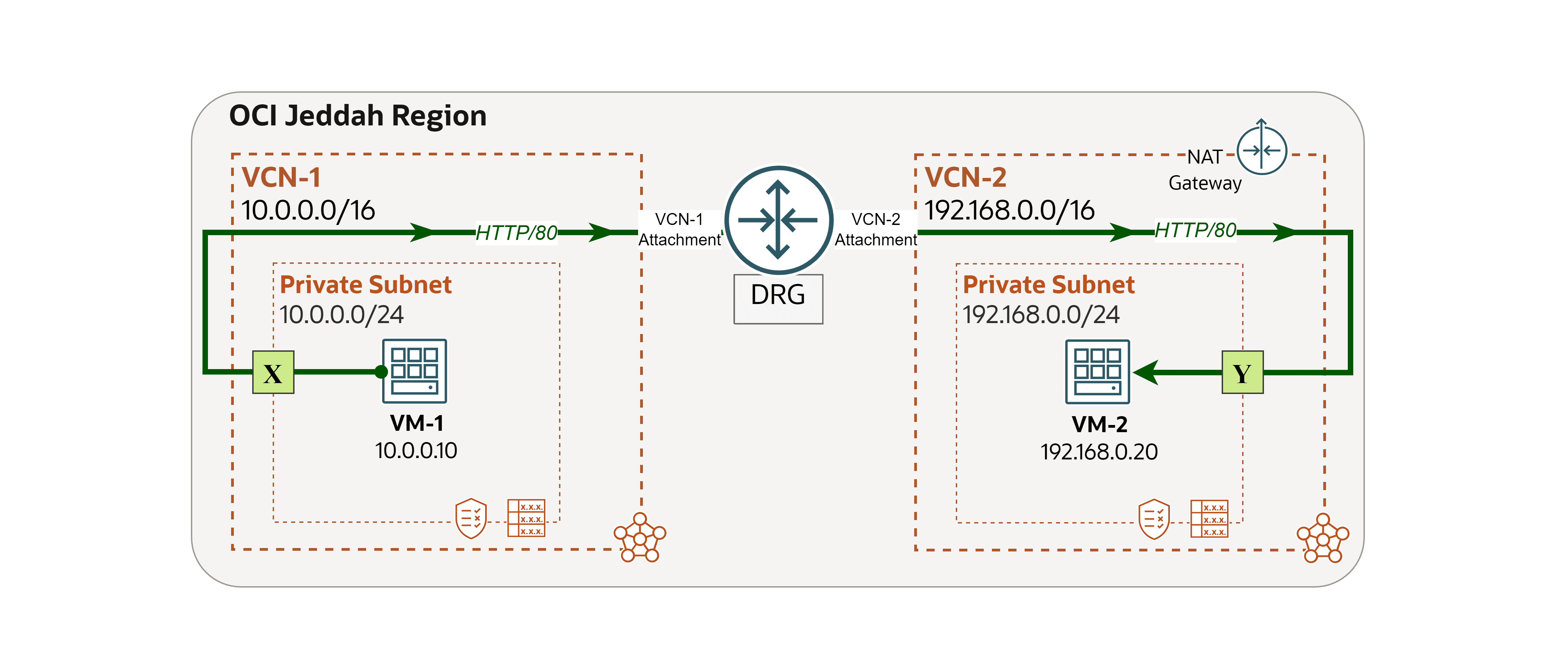
Note: In this example, we focus only on logging at point Y, where the destination is located. However, you can apply the same steps to enable and analyze logs at point X (the source of the traffic) to gain additional visibility into the overall traffic flow.
We encountered a network issue and we will use VCN Flow Logs to trace and address the root cause.
Issue: VM-1 cannot access a website hosted on VM-2.
-
Log in to
VM-2and run the following command to check if the website is running locally.curl localhost
-
Log in to
VM-1and run the same command to test connectivity to VM-2.curl 192.168.0.20You will see that the request fails. In the next steps, we will use
VCN-2flow logs to investigate the cause.
-
Now, let us enable the logs. We will begin by creating a Capture Filter, which is a simple rule set used in OCI to determine which network traffic should be captured for logging or mirrored to Virtual Test Access Points (VTAPs).
- Log in to the OCI Console and make sure you are in the right region.
- Click the hamburger menu (≡) from the upper left corner.
- Click Networking.
- Click Capture filters.

-
Click Create capture filter.

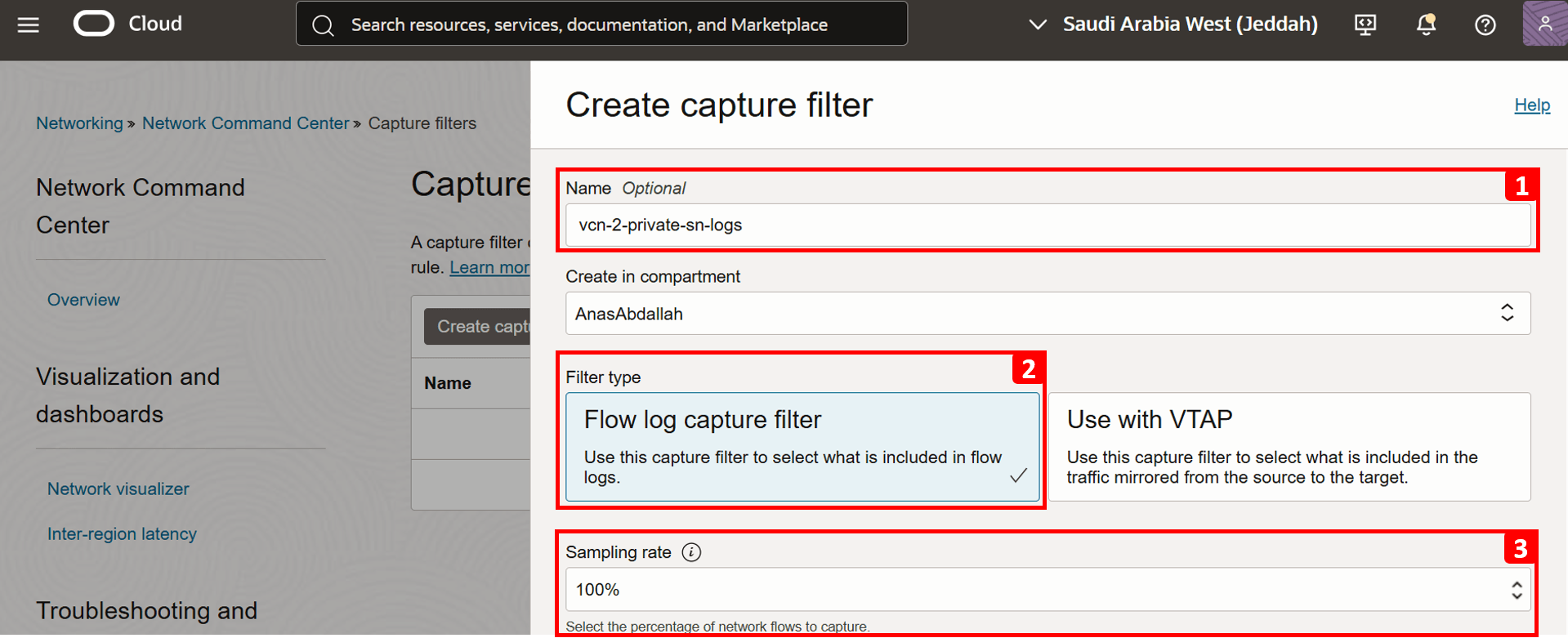
- Enter
vcn-2-private-sn-logsas Name. - Select Flow log capture filter as Filter type.
- Set the Sampling rate to 100%. This defines the percentage of network flows to capture, in this case, we want to log all traffic.
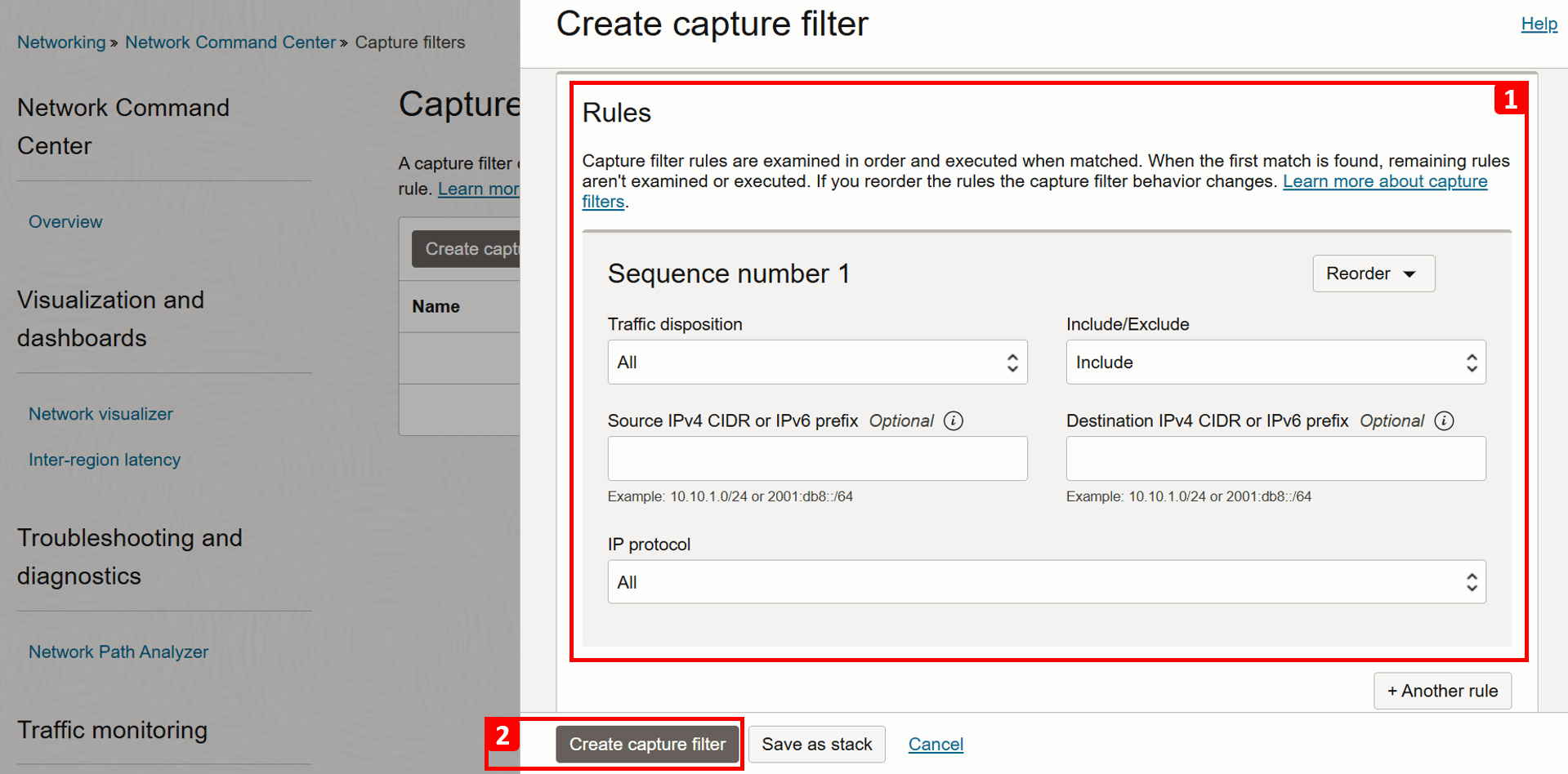
- Leave all other settings at their default values.
- Click Create capture filter.
- Enter
-
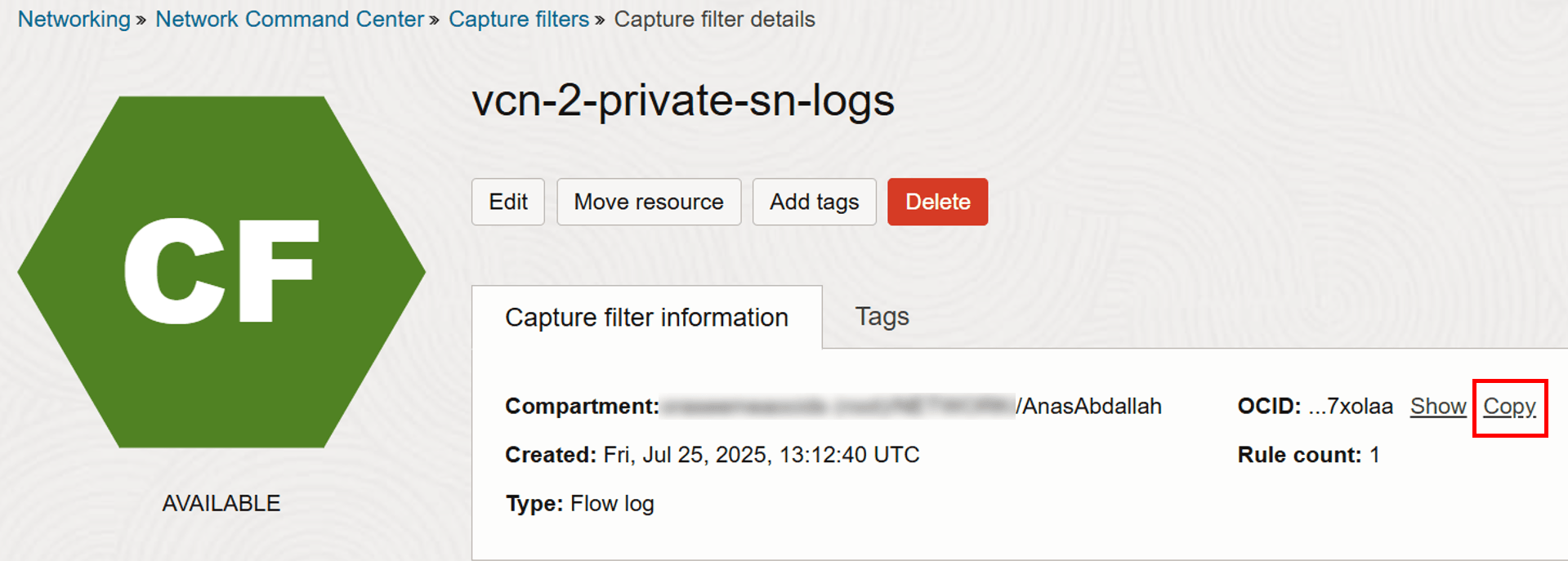
Once the capture filter is created, click Copy to copy its OCID, as you will need it in the next steps.
-
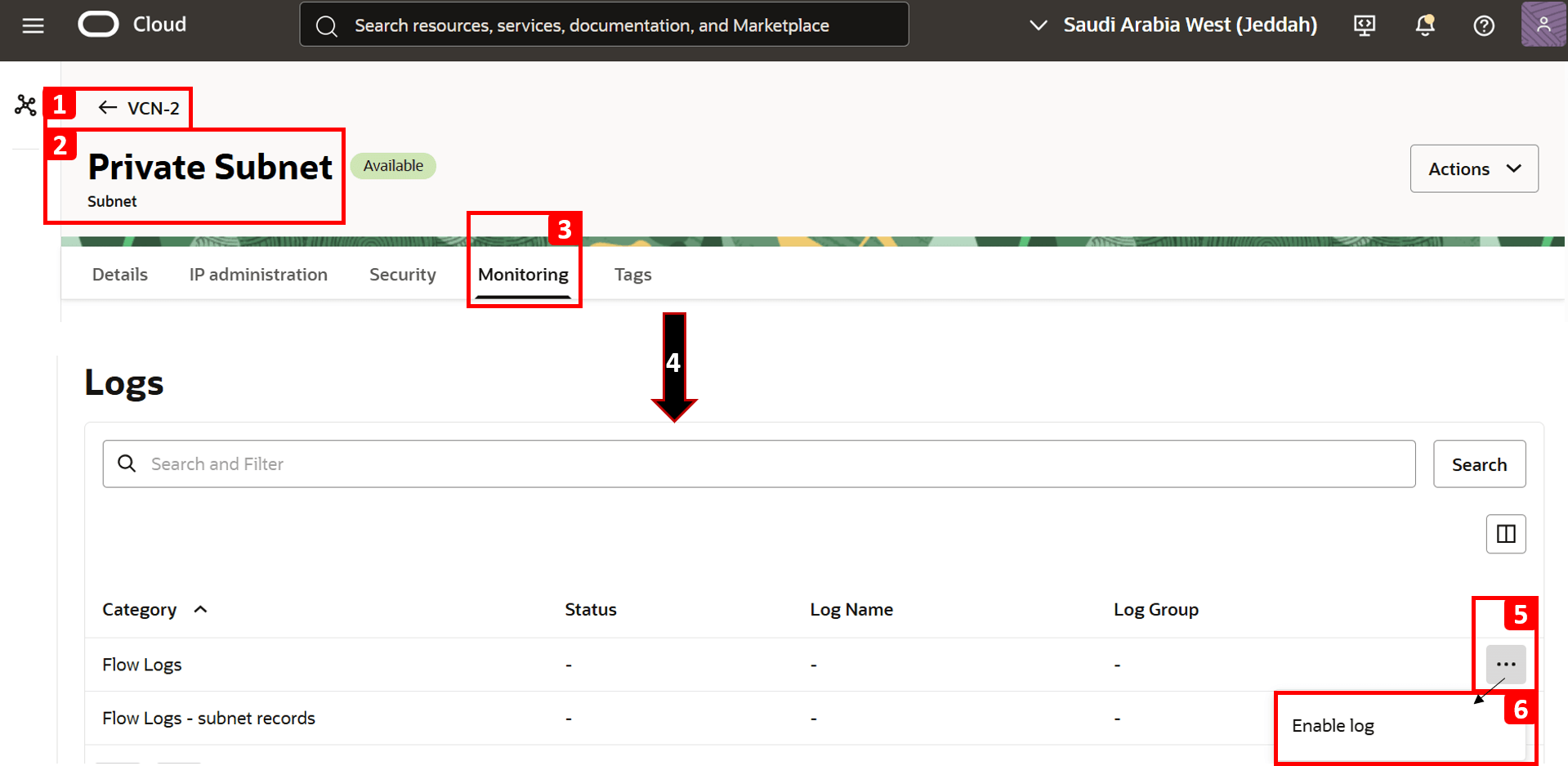
Now, we are ready to enable the logs.
- Navigate to
VCN-2. - Open Private Subnet, where
VM-2resides. - Click Monitoring.
- Scroll down to the Logs section.
- Click the three dots (•••) next to the Flow Logs category.
- Click Enable log.
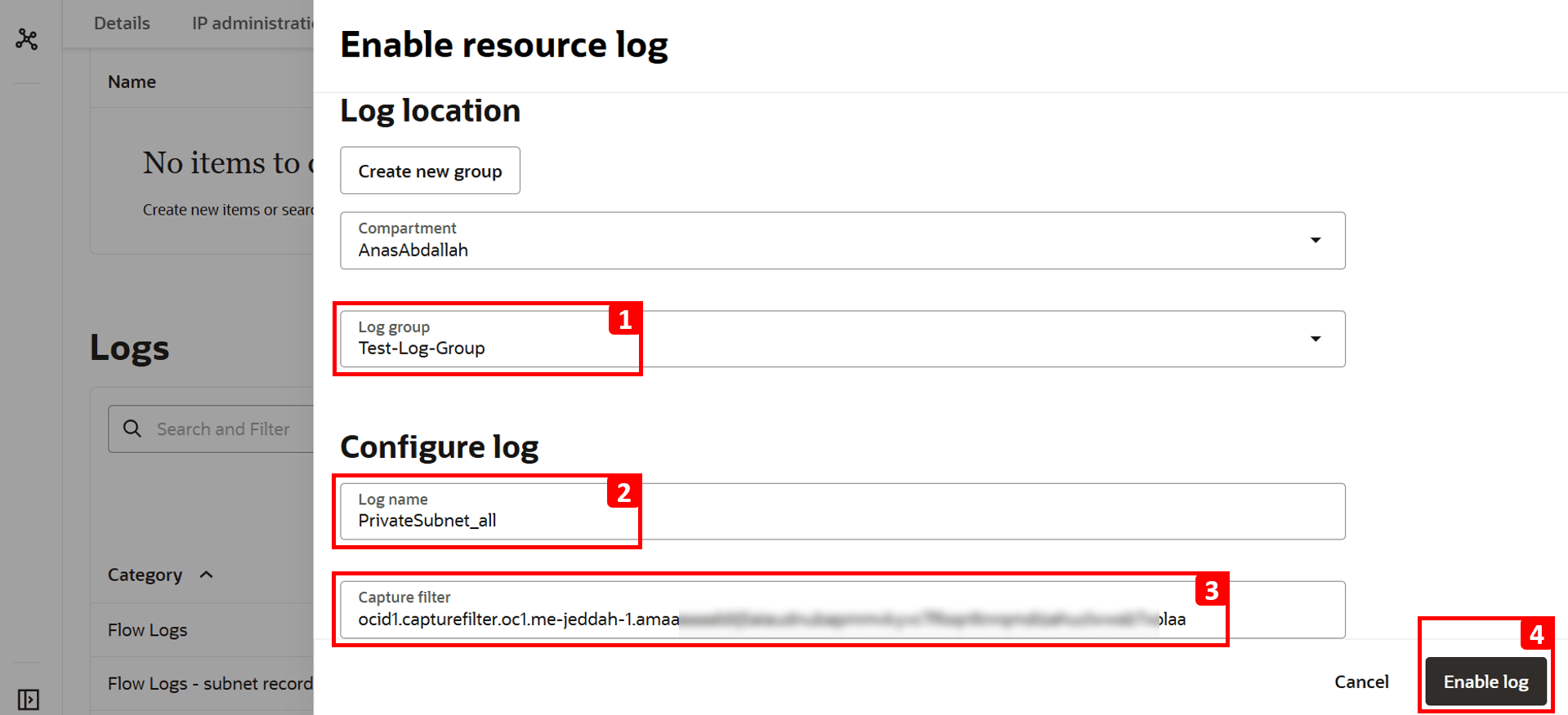
- Select Log Group. If you do not have one already, create a new log group.
- Log name is filled automatically.
- Paste the Capture filter OCID copied earlier.
- Click Enable log.
- Navigate to
-
Flow logs are now Active.

-
Repeat the same test to generate traffic by running the following command in
VM-1.curl 192.168.0.20
-
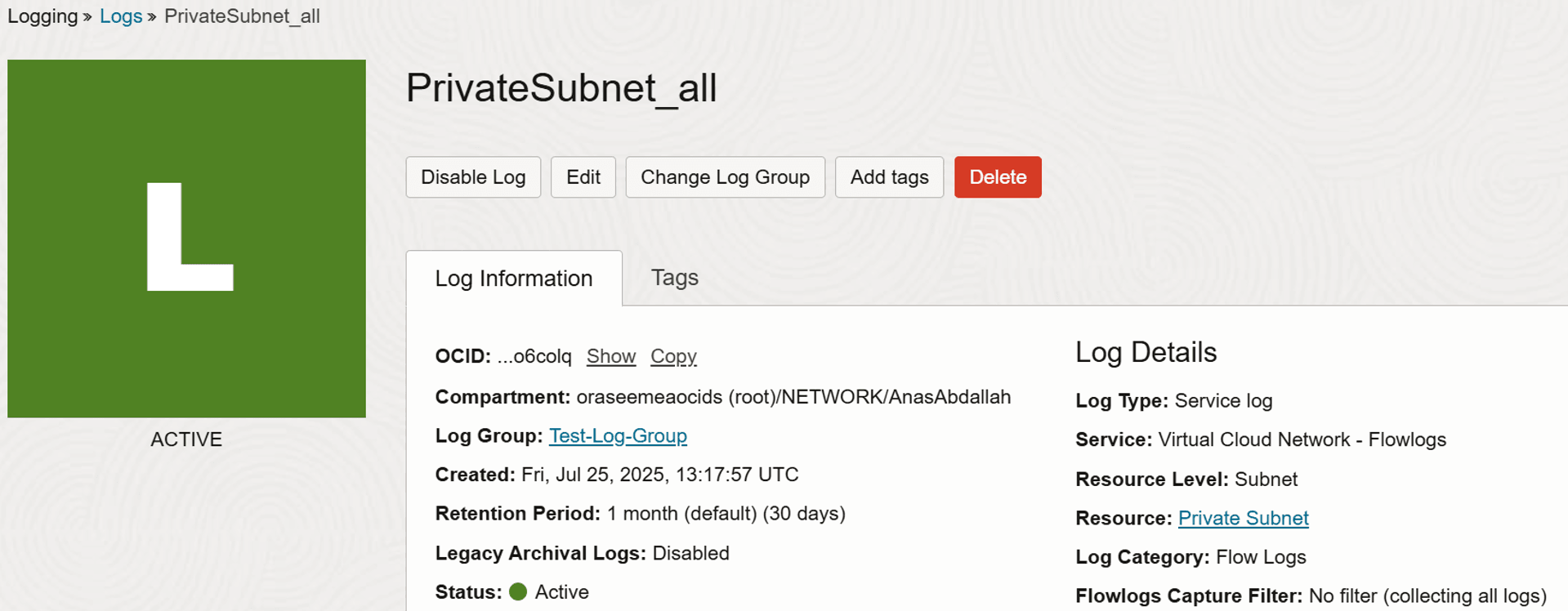
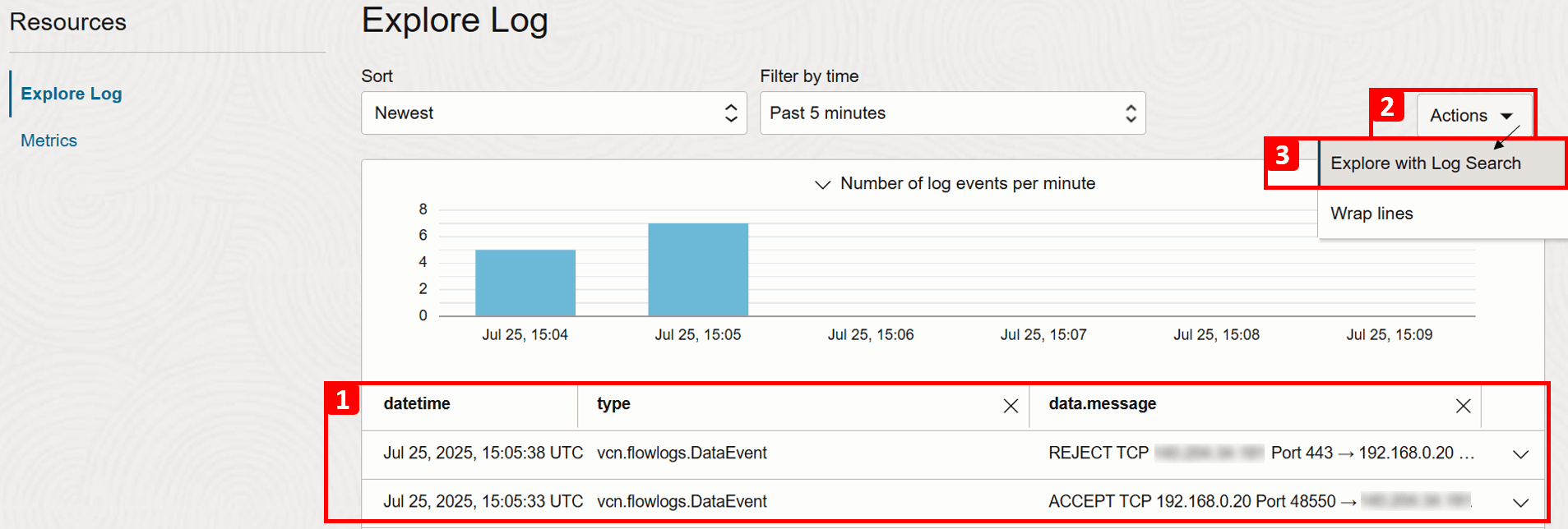
Return to the Logs section and click Log Name created earlier.

- Scroll down and you will see logs showing traffic entering or leaving the network.
- Click Actions.
- Click Explore with Log Search to apply advanced filters and narrow down the log results.
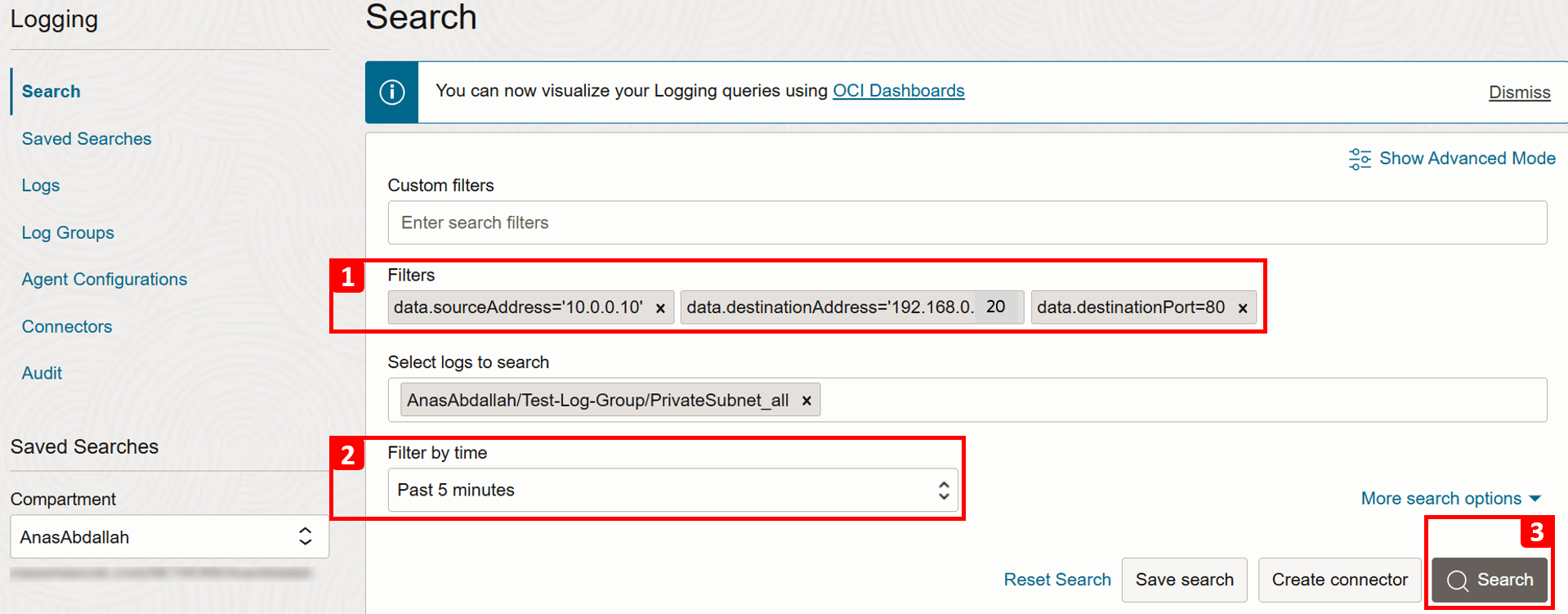
- Apply the following Filters to match our test connection.
- Source IP (
VM-1):data.sourceAddress = '10.0.0.10'. - Destination IP (VM-2):
data.destinationAddress = '192.168.0.20'. - Destination Port (HTTP):
data.destinationPort = 80.
- Source IP (
- Adjust the time range in Filter by time if needed, or leave it as the default Past 5 minutes.
- Click Search.
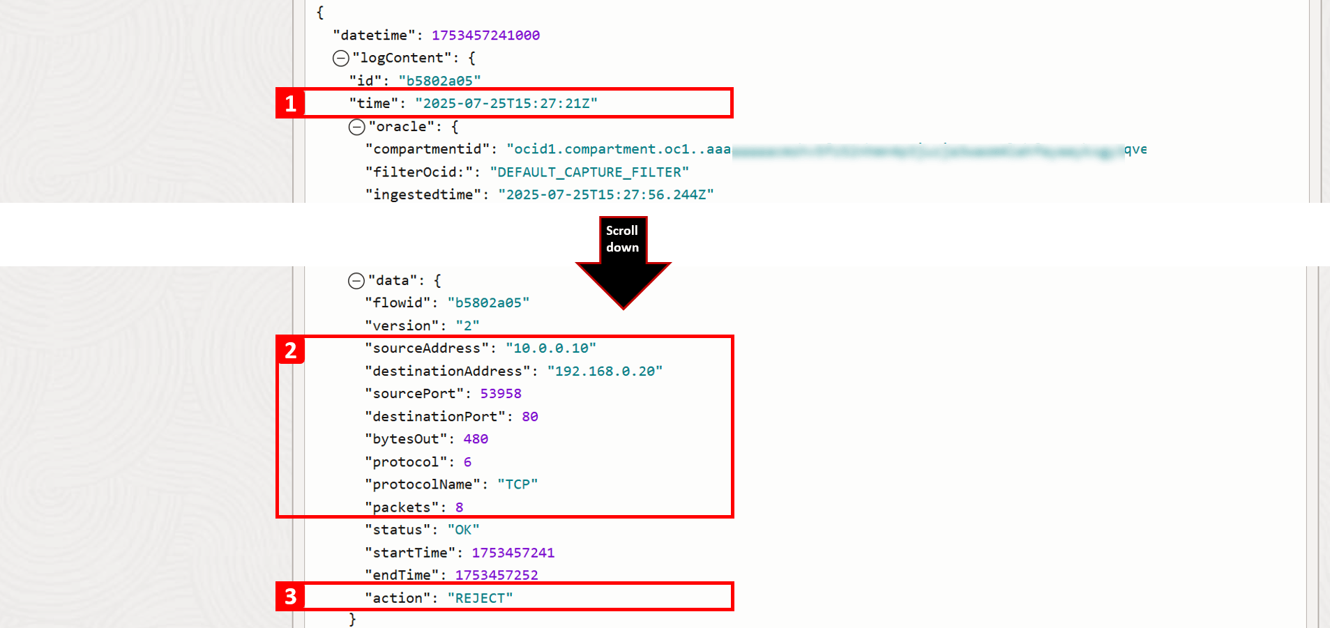
- Review the results that match your search criteria.
- Expand the record details.

-
For this particular record, you can view detailed information about this traffic flow. Key fields to note include:
- Timestamp: The exact date and time the traffic reached the subnet.
- Connection details: Such as source IP address, destination IP address, and port number.
- Action: Shows how the traffic was handled; in this case, it was REJECT. This confirms the root cause of the issue, there is no security rule in place to allow HTTP traffic to
VM-2.
-
In order to allow HTTP traffic to reach
VM-2, you have two options:- Security List: Applied at the subnet level, which means that all VNICs in a subnet are subject to the same set of security lists.
- NSG: Applied at the resource level (VNIC level).
-
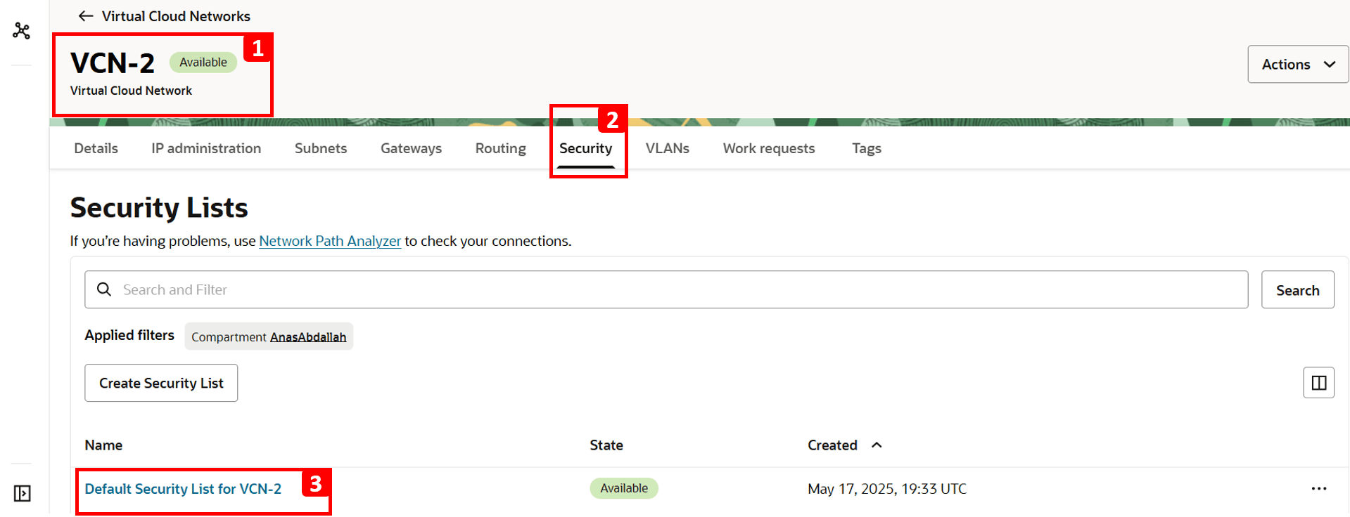
Here, we are going to allow it from the default security list which is already associated with the
VM-2subnet.- Navigate to
VCN-2, where the destination VM is located. - Click Security.
- Click Default Security List for VCN-2.
- Click Security rules.
- The table shows which traffic is allowed. Everything else including HTTP is denied by default since there is no rule to allow it. That is why
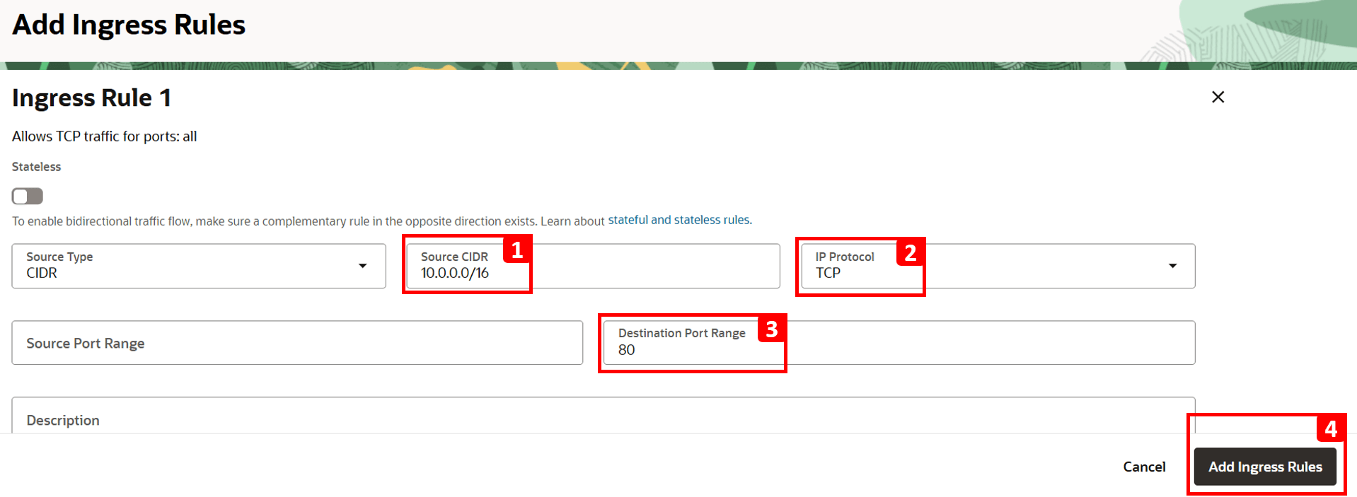
VM-1cannot access the website hosted onVM-2. - To fix this, click Add Ingress Rules.

- Enter
10.0.0.0/16as Source CIDR (this is the CIDR forVCN-1). - Select TCP as IP Protocol.
- Set 80 as Destination Port.
- Click Add Ingress Rules.
- Navigate to
-
Log in to
VM-1and run the same command to test connectivity toVM-2.curl 192.168.0.20You should now see that the website is reachable.

-
Return to the logs and repeat the same steps as before to perform a new search.
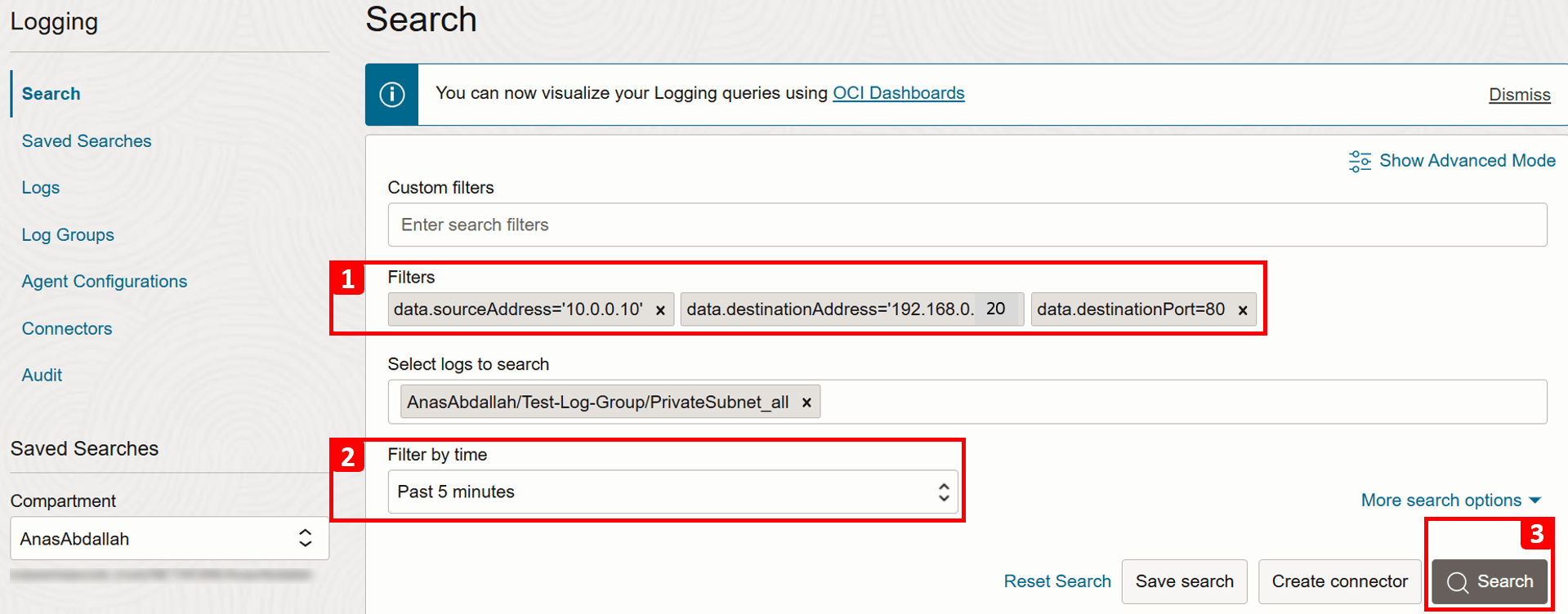
- Apply the following Filters to match our test connection.
- Source IP (
VM-1):data.sourceAddress = '10.0.0.10'. - Destination IP (
VM-2):data.destinationAddress = '192.168.0.20'. - Destination Port (HTTP):
data.destinationPort = 80.
- Source IP (
- Adjust the time range if needed, or leave it as the default (Past 5 minutes).
- Click Search.
- Review the results that match your search criteria.
- Expand the record details.

- Apply the following Filters to match our test connection.
-
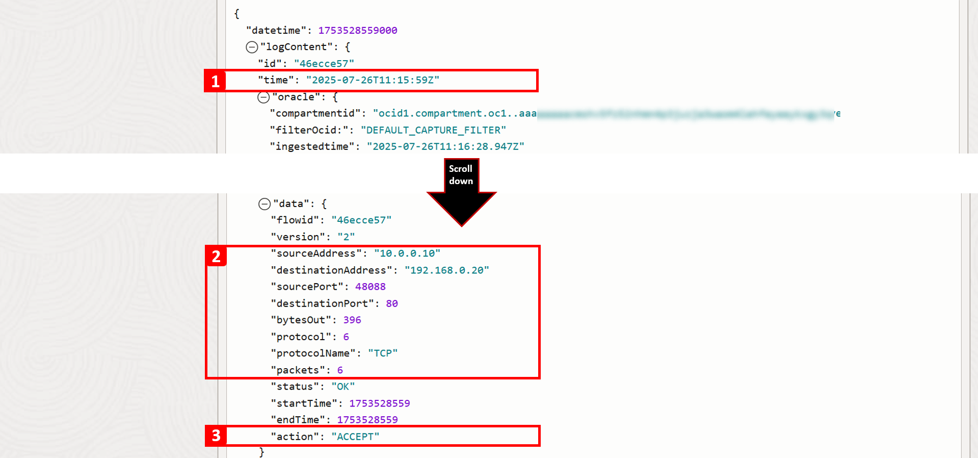
For this particular record, you can view detailed information about this traffic flow. Key fields to note include:
- Timestamp: The exact date and time the traffic reached the subnet.
- Connection details: Such as source IP, destination IP, and port number.
- Action: Shows how the traffic was handled. After resolving the issue, you should now see that the traffic is ACCEPT.
Next Steps
We explored how to troubleshoot fundamental networking issues in OCI by examining architecture, routing, and security configurations. These core checks help resolve most common connectivity problems. The next tutorial will focus on advanced scenarios and more real-world use cases.
Acknowledgments
- Authors - Anas Abdallah (Cloud Networking Specialist), Sachin Sharma (Cloud Networking Specialist)
More Learning Resources
Explore other labs on docs.oracle.com/learn or access more free learning content on the Oracle Learning YouTube channel. Additionally, visit education.oracle.com/learning-explorer to become an Oracle Learning Explorer.
For product documentation, visit Oracle Help Center.
Troubleshoot Basic Network Issues in Oracle Cloud Infrastructure
G40501-01