6.1 Using Geofences for Location-based Analytics
A geo fence is a virtual boundary in a real world geographical area. This virtual boundary can be used to find the object's position or location, with respect to the geo fence.
For example, the object position can be:
-
Near to geo fence
-
Exit geo fence
-
Based on Stay Duration in geo fence
-
Enters geo fence
-
Present inside geo fence
6.1.1 Selecting a Tile Layer
Tile layer is the base map that provides immediate geographic context. Tiles are stored in the map tile server. These tile layers contains huge amount of data pertaining to:
-
Roads, railways, waterways, etc.
-
Restaurants, shops, stations, ATMs, and more
-
Walking and cycling paths
-
Buildings, campuses, etc.
Oracle GoldenGate Stream Analytics supports four types of tile layers.
6.1.1.1 Elocation Tile Layer
Elocation tile layer is an Oracle tile layer.
To apply the Elocation Tile Layer:
-
Click the user name in the top right corner of the screen.
-
Click Preferences. The Preferences page opens.
-
Click Map.
-
Under Tile Layer, choose Elocation Tile Layer option from the drop-down list.
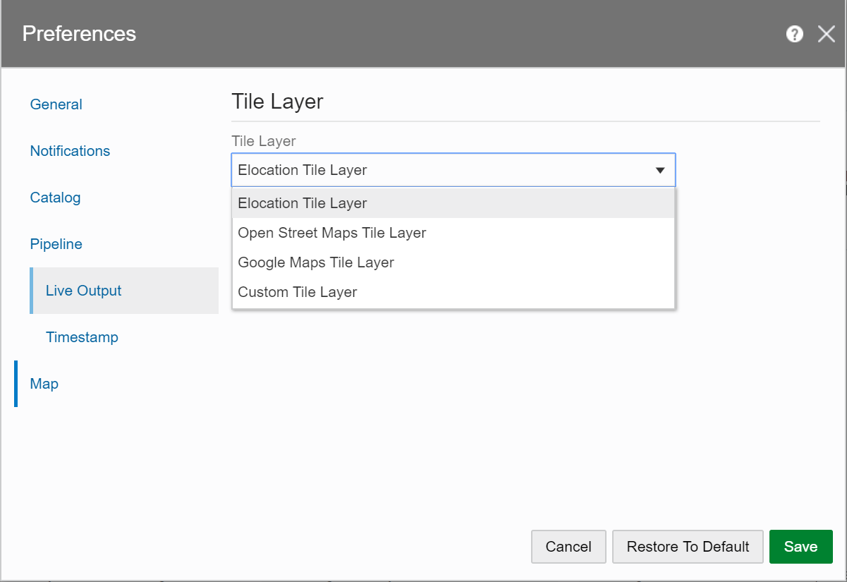
Description of the illustration elocationtilelayeroptions.png -
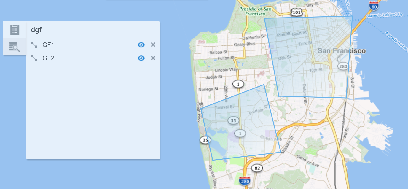
Click Save. The map looks like this:
6.1.1.2 Open Street Maps Tile Layer
Open Street Maps tile layer is a free map.
To apply the Open Street Maps Tile Layer:
-
Click the user name in the top right corner of the screen.
-
Click Preferences. The Preferences page opens.
-
Click Map.
-
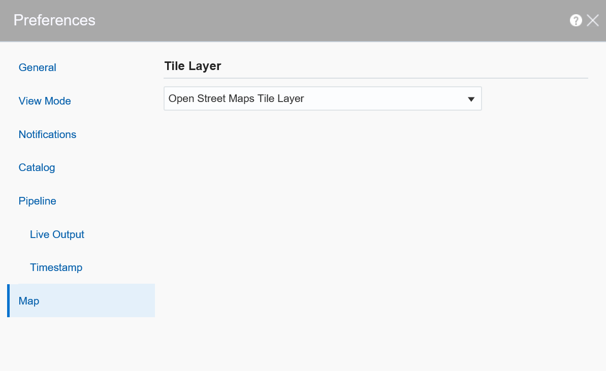
Under Tile Layer, choose Open Street Maps Tile Layer option from the drop-down list.
-
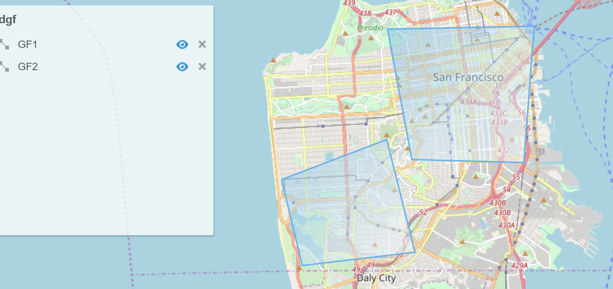
Click Save. The map looks like this:
6.1.1.3 Google Maps Tile Layer
Oracle Stream Analytics has added the support for Google tile layer which displays Google maps in Spatial patterns and visualizations.
To apply the Google Tile Layer:
-
Click the user name in the top right corner of the screen.
-
Click Preferences. The Preferences page opens.
-
Click Map.
-
Under Tile Layer, choose Google Maps Tile Layer option from the drop-down list.
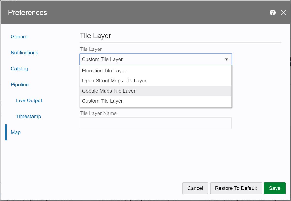
- Provide details for the following fields:
- Lib URL — the Google maps javascript lib url.
Note:
If you do not provide the Lib Url, Oracle maps uses the default Lib Url:
- Authentication Type:
- API key — API key for authentication which you can get from Google. The URL would look like this: https://maps.googleapis.com/maps/api/js?key=YOUR_API_KEY&callback=initMap.
- Client ID — your client ID which identifies you as a Maps API for Business customer
- Lib URL — the Google maps javascript lib url.
-
Click Save.
Note:
To use Google maps tile layer, the usage of the maps must meet the terms of service defined by Google (http://code.google.com/apis/maps/faq.html#tos).6.1.1.4 Custom Tile Layer
Oracle Maps, by default, supports Elocation tile layer which has limited zoom levels. Oracle Stream Analytics now allows you to customize the zoom levels for a tile layer, in specific cases where you need a detailed, higher zoom view of confined spaces such as, restaurants, airports, etc.
To apply the Custom Tile Layer:
-
Click the user name in the top right corner of the screen.
-
Click Preferences. The Preferences page opens.
-
Click Map.
-
Under Tile Layer, choose Custom Tile Layer option from the drop-down list.
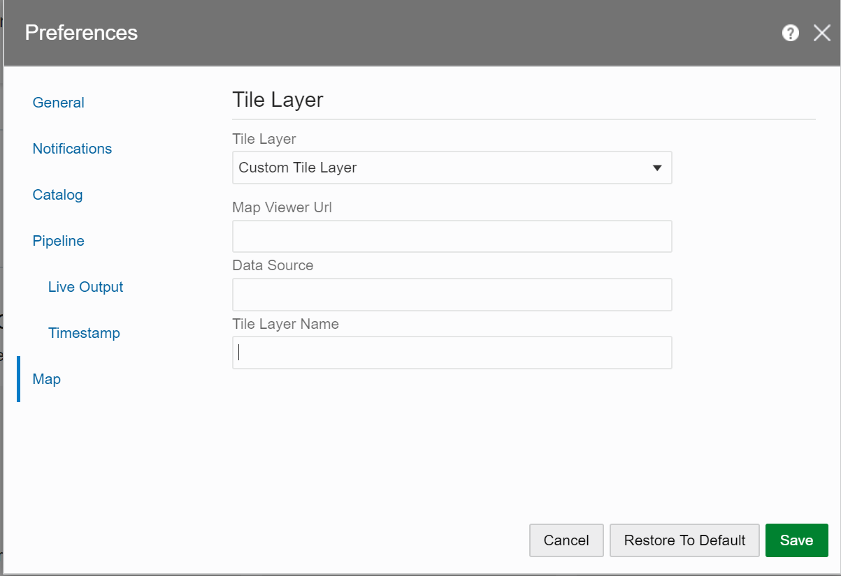
- Provide details for the following fields:
- Map Viewer Url — http://yourmapviewer => another address where you have an Oracle map viewer running
- Data Source — a connection to a database where you define your style. It should be an OSA data source, or a custom one which allows to define our maps via mapbuilder.
- Tile Layer Name — name of the defined tile layer
-
Click Save. The map looks like this:
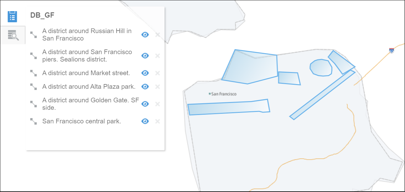
Note:
Once you have modified the global parameters to customize the tile layer, the map is updated to use the custom tile layer. These customizations, will then be applied to all geofences.6.1.2 Managing Geofences using the Map Editor
You can create, edit, and update manual geofence using the built-in map editor. Only polygon geo fences are allowed.
6.1.2.1 Creating a Geo Fence
To create a manual geo fence:
-
On the Catalog page, click Create New Item and select Geo Fence from the drop-down list.
- On the Type Properties screen, enter the following details:
- Name
- Description
- Tags
- Geo Fence Type: Select Manually Created Geo Fence from the drop-down list.
-
Click Save.
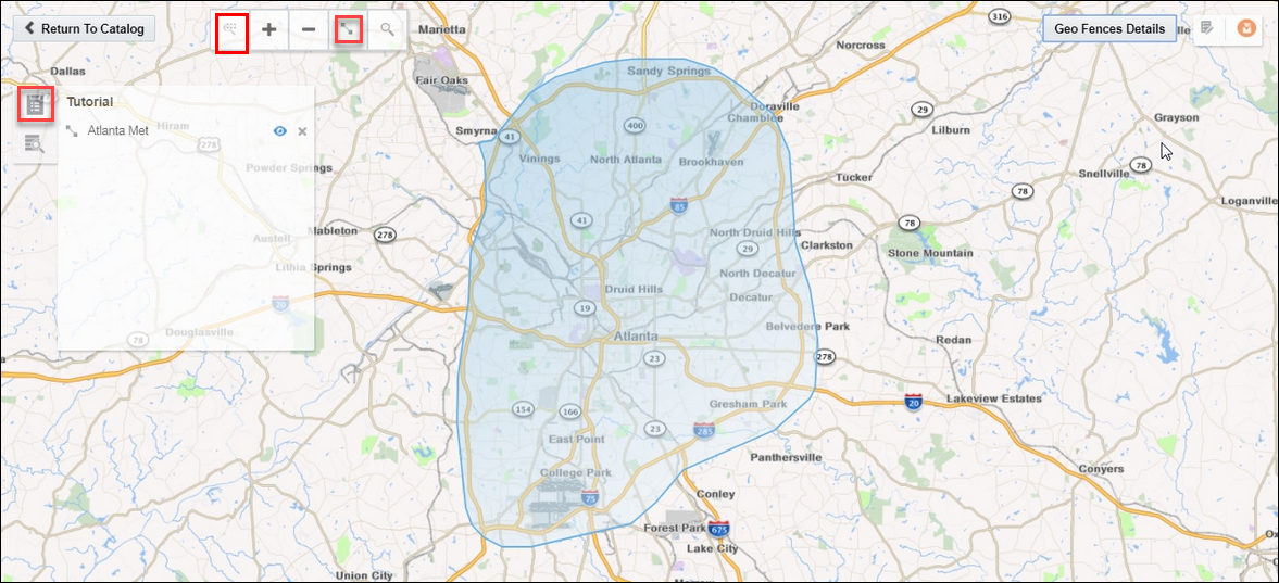
In the Geo Fence Editor:- You can create the geo fence.
-
Navigate through the map using the zoom icons
-
Zoom a specific area on the map, using the Marquee Zoom tool. Mark an area using the marquee zoom and that area in map is zoomed.
-
Mark the area around a region to create a geo fence, using the Polygon Tool.
- Save the changes made to your geofence.
6.1.3 Importing a Geofence from a Database
To import a geo fence from a database:
-
On the Catalog page, Create New Item and then select Geo Fence from the drop-down list.
- On the Type Properties screen, enter the following details:
- Name
- Description
- Tags
- Geo Fence Type: Select Geo Fence from Database from the drop-down list.
- Click Next.
- On the Geo Fence Details screen, select a Connection.
- Click Next.
- On the Shape screen, select a database table from the drop-down list. Only the database tables that contain
SDO Geometrytype fields are available in the drop-down list.You can also define or change the key fields on this screen.
-
Click Save.
You can see all the geo fences contained in the selected database.
Note:
You cannot edit or update database-based geo fences.6.1.4 Using Spatial Patterns in Pipeline Stages
Spatial patterns enables analysis of streams that contain geolocation data. Use them to determine how events relate to predefined geo fences in your maps.
6.1.4.1 Clearing Objects Outside a Geo Fence
Use the Geo Filter pattern to filter out objects that are not inside the Geofence.
For example, if users move from one geographical location to another, you can send promotional messages to the users when they are inside a specified geo fence.
To use this pattern, provide suitable values for the following parameters:
-
Geo Fence: Select a geo fence to analyze.
-
Latitude: Select a field containing the latitude value.
-
Longitude: Select a field containing the longitude value.
-
Object Key: Select a field that uniquely identifies the object. This field is the partitioning criteria and is also the unique object identifier.
-
Coordinate System: Enter the default value 8307. This is the only value supported.
The outgoing shape displays Status and PlaceName as two extra columns in the output along with the incoming shape, where Status is Inside if the object is inside geo fence (else the event is not considered) and PlaceName is the name of geo fence with which status is being evaluated.
6.1.4.2 Tracking Objects using a Geo Fence
Use the Geo Fence pattern to track object relation with a virtual boundary called geo fence.
Relations can be Enter, Exit, Stay, or Near with respect to a geo fence. For example, you can trigger an alert when an object enters the geo fence. You can also analyze a stream containing geo-location data. It helps in determining how events are related to a polygon in a geo fence.
To use this pattern, provide suitable values for the following parameters:
- Geo Fence: Select a geo fence to analyze.
- Latitude: Select the field containing latitude value.
- Longitude: Select the field containing longitude value.
- Object Key: Select the object key field. This field is used as the partitioning criteria and also used to uniquely identify objects
- Tracking Events: Select the appropriate value.
- Coordinate system: The default and the supported value is 8307.
-
Distance Buffer: This parameter is enabled only if you select Near option in Tracking Events. This field is a buffer for filtering results. Only those events or objects which are within the specified distance from the geo fence are displayed in events table with status as
Near. This value must be less than 10000 kilometers. -
Stay Duration: This parameter is enabled only if you select Stay in Tracking Events. You can specify the stay duration. This duration is a filter for objects inside the geo fence. If an object stays for a duration more than the specified duration, only then the events are considered, else events are filtered out.
The outgoing shape displays Status and PlaceName as two extra columns in the output along with the incoming shape, where Status is one of Enter, Exit, Stay, or Near based on how the object behaves with geo fence. PlaceName is the name of geo fence with which status is being evaluated.
6.1.4.3 Getting Direction of a Moving Object
Use the Direction pattern to get the direction of a moving object.
For example, you can evaluate the direction of a moving truck.
To use this pattern, provide suitable values for the following parameters:
-
Latitude: Select the field containing latitude value.
-
Longitude: Select the field containing longitude value.
-
Object Key: Select field that uniquely identifies object. E.g. Vehicle Id.
-
Coordinate System: The default value is 8307 and this is the only value supported.
Note:
Make sure that you do not use any names for the fields that are already part of the incoming stream.The outgoing shape displays direction as one of the columns, which is of type String along with the incoming shape.
6.1.4.4 Obtaining Geographic Coordinates
Use the Geo Code pattern to get geographic coordinates (like latitude and longitude) for an address or a zip code.
Ensure that you have set the proxy details in System Settings.
To use this pattern, provide suitable values for the following parameters:
-
Name: Select the place name.
-
Street: Select the street name.
-
City: Select the city name.
-
Region: Select the region.
-
Country: Select the country. You can hard code the value such as US for United States and IN for India.
-
Postal Code: Select the zip or postal code.
The output from the pattern are the latitude and longitude corresponding to the input.
6.1.4.5 Calculating Distance between Objects in a Stream
Use the Interaction: Single Stream pattern to get interaction of an object with every other object in a stream.
For example, you can see if a set of sailing ships are too close to each other.
To use this pattern, provide suitable values for the following parameters:
-
Geometry: Select the field that contains the shape of the object and is of type
SDO_GEOMETRY. -
Object Key: Select the field used to uniquely identify an object and is used for partitioning of data where supported.
-
Coordinate System: The default value is 8307 and this is the only value supported.
The outgoing shape contains two more fields along with the incoming shape: isInteract and distance. isInteract is trueif two shapes interact with each other, i.e., any or some portion of the two objects overlap. distance between them is 0, if no overlapping is observed; isInteract is false and distance is shown between those two objects as a positive number.
6.1.4.6 Calculating Distance between Objects in Two Streams
Use the Interaction: Two Stream pattern to get interaction of an object in one stream with objects in another stream. Two shapes are said to interact with each other if any part of the shape overlaps. If two shapes interact, the distance between them is zero.
To use this pattern, provide suitable values for the following parameters:
-
Geometry: Select a suitable value for geometry.
-
Object Key: Select the object key.
-
Event Stream 2: Select the second event stream.
-
Geometry: Select a value for geometry within the second stream.
-
Object Key: Select the object key within the second stream.
-
Coordinate System: The default value is 8307 and this is the only value supported.
The outgoing shape contains two additional fields along with the incoming shape: isInteract and distance. isInteract is trueif two shapes interact with each other, i.e., any or some portion of the two objects overlap. distance between them is 0, if no overlapping is observed; isInteract is false and distance is shown between those two objects as a positive number.
6.1.4.7 Creating Geo Fence
Use the Point to Polygon pattern to create a Geo Fence using the default coordinate system, given the latitude, longitude, width, and length.
For example, if you know the length and breadth of a group of a fleet of ships, you can get the shape of a ship using the position coordinates, where the coordinates keep changing as the ship moves.
To use this pattern, provide suitable values for the following parameters:
-
Latitude: Select the field containing latitude value.
-
Longitude: Select the field containing the longitude value.
-
Object Key: Select a suitable value for the object key.
-
Length: Select field that contains the length of the object.
-
Width: Select a field that contains the width of the object.
-
Coordinate System: The default value is 8307 and this is the only value supported.
-
Buffer: Enter a positive value to be used as the geometry buffer.
The outgoing shape contains derived shape (Rectangle/Polygon of type SDO_Geometry) of an event based on its coordinate (latitude,longitude) and dimension (length, width).
6.1.4.8 Monitoring Proximity between Objects in a Stream
Use the Proximity: Single Stream pattern to get proximity of each object with every other object in a stream.
For example, if there is stream of flying airplanes and the distance buffer is 1000 meters. You can raise an alert as the two planes come into a proximity of 1000 meters or less.
To use this pattern, provide suitable values for the following parameters:
-
Latitude: Select field that contains the latitude value.
-
Longitude: Select field that contains the longitude value.
-
Object Key: Select field that uniquely identifies the object in the stream.
-
Coordinate System: The default value is 8307 and this is the only value supported.
-
Distance Buffer: Enter a proximity value for the distance buffer. Proximity of objects will be output only when they are within the specified distance buffer. Select an appropriate unit for the distance. This value must be less than 10000 kilometers.
The outgoing shape displays distance as another column, which is the distance between two object under consideration along with the incoming shape.
6.1.4.9 Monitoring Proximity between Objects in Two Streams
Use the Proximity: Two Stream pattern to determine the proximity between object in stream 1 with all other objects in stream 2.
The distance buffer acts as a filter in this pattern stage. For example, if there is a driver and passenger stream, you can get the proximity of each passenger with every other driver using a filter criteria of within a distance of 1 km.
To use this pattern, provide suitable values for the following parameters:
-
Latitude: Select field containing latitude value from stream 1.
-
Longitude: Select field containing longitude value from stream 1.
-
Object Key: Select field that uniquely identifies object in stream 1.
-
Event Stream 2: Select the second event stream.
-
Latitude: Select field containing latitude value from stream 2.
-
Longitude: Select field containing longitude value from stream 2.
-
Object Key: Select field that uniquely identifies object in stream 2.
-
Coordinate System: The default value is 8307 and this is the only value supported.
-
Distance Buffer: Enter a proximity value for the distance buffer. This field acts as a filter criteria of two objects and the objects that do not fall in this distance (distance between them is more than chosen distance buffer) are filtered from result set. This value must be less than 10000 kilometers.
Note:
When a pipeline with this pattern has a database reference with cache enabled, the pattern does not display any output in the live output stream.The outgoing shape displays distance as another column, which is the distance between two object under consideration along with the incoming shape.
6.1.4.10 Obtaining the Proximity of an Object from a Geo Fence
Use the Proximity: Stream with Geo Fence pattern to get proximity of an object with a virtual boundary or geo fence.
For example, if you have certain stores in the city of California, you can send promotional messages as soon as the customer comes into a proximity of 1000 meters from any of the stores.
To use this pattern, provide suitable values for the following parameters:
-
Geo Fence: Select a geo fence that you like to analyze.
-
Latitude: Select the field containing latitude value.
-
Longitude: Select the field containing longitude value.
-
Object Key: Select the field that uniquely identifies object. Example, Vehicle Id.
-
Coordinate System: The default value is 8307 and this is the only value supported.
-
Distance Buffer: Enter a proximity value for the distance buffer. This field acts as a filter criteria for events and the events that do not fall in this distance (distance between them is more than chosen distance buffer) are filtered from result set. This value must be less than 10000 kilometers.
The outgoing shape displays distance as another column, which is the distance between the object and geo fence under consideration along with the incoming shape.
6.1.4.11 Finding Nearest Place using the Geographical Coordinates
Use the Reverse Geo Code: Near By pattern to obtain nearest place for the specified geographical coordinates.
Ensure that you have set the proxy details in System Settings.
To use this pattern, provide suitable values for the following parameters:
-
Latitude: Select the latitude.
-
Longitude: Select the longitude.
-
Object Key: Select the object key.
-
Coordinate system: The default value is 8307 and this is the only value supported.
The outgoing shape displays PlaceName as an additional column along with the incoming shape. This column is the nearest place for specified longitude and latitude.
6.1.4.12 Finding Nearest Place Details using the Geographical Coordinates
Use the Reverse Geo Code: Near By Place pattern to obtain the near by location with granular information like city, country, street etc. for the specified latitude and longitude.
Ensure that you have set the proxy details in System Settings.
To use this pattern, provide suitable values for the following parameters:
-
Latitude: Select a field containing the latitude value.
-
Longitude: Select a field containing the longitude value.
-
Object Key: Select a field that uniquely identifies the object.
-
Coordinate system: The default value is 8307 and this is the only value supported.
The outgoing shape displays additional columns for place corresponding to the coordinates (latitude,longitude)- houseNumber, street, city, region, country, and postal code.
6.1.4.13 Determining Average Speed
Use the Spatial: Speed pattern to determine the average speed using all data points from a time window. This pattern uses the default slide value. For example, to analyze the average speed of a car.
To use this pattern, provide suitable values for the following parameters:
-
Latitude: Select field name that contains the latitude value.
-
Longitude: Select field name that contains the longitude value.
-
Object Key: Select a suitable value for the object key. Example of object key is Vehicle ID, or anything that uniquely differentiates the moving object.
-
Coordinate System: The default value is 8307 and this is the only value supported.
-
Window Range: Select a time range over which the speed is being calculated for an event. For example, if
window range=5 secondsand object key isvehicle ID, then all the events with samevehicle IDreceived over last 5 seconds are used to calculate the average speed of that event.
The outgoing shape contains speed as an added field along with the incoming fields. This is a numeric field, but the speed is measured in miles per hour.
