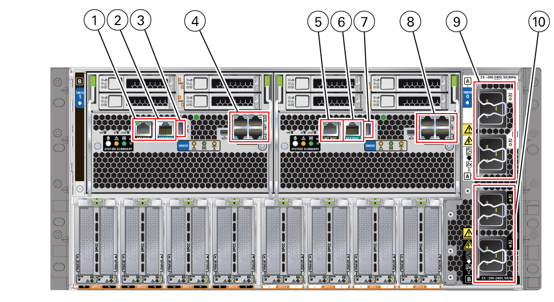
Back Panel Connector Locations
The following illustration shows and describes the locations of the back panel connectors. Use this information to set up the server, so that you can access diagnostic tools and manage the server during service.
The following figure shows the locations of the server back panel connectors and ports.

| Callout | Description | System/SMOD | Available On |
|---|---|---|---|
|
1 |
Net management port (NET MGT) |
System B – SMOD1 |
Dual 4-socket systems only |
|
2 |
Serial management port (SER MGT) |
System B – SMOD1 |
Dual 4-socket systems only |
|
3 |
USB 3.0 port |
System B – SMOD1 |
Dual 4-socket systems only |
|
4 |
|
System B – SMOD1 |
Dual 4-socket and single 8-socket systems |
|
5 |
Net management port (NET MGT) |
System A – SMOD0 |
All systems |
|
6 |
Serial management port (SER MGT) |
System A – SMOD0 |
All systems |
|
7 |
USB 3.0 port |
System A – SMOD0 |
All systems |
|
8 |
NET0, NET1, NET2, and NET3 ports on all systems |
System A – SMOD0 |
All systems |
|
9 |
Power connectors 2 and 3 |
System A – SMOD0 |
Always connect all four power supplies. Connect to 200-240 VAC only. |
|
10 |
Power connectors 0 and 1 |
System B –SMOD1 |
Always connect all four power supplies. Connect to 200-240 VAC only. |