Install the Midplane Assembly

Use this procedure to install the midplane assembly.

This procedure requires removing the server from the rack. Removing all front and back components lessens the weight of the server.

This is a cold-service procedure. Power down the system and disconnect all power cables before removing the server access panels.

Caution:

Hazardous voltage. Possibility of electrical shock if the power cables are connected to the server when accessing the midplane and bus bar assembly.

Caution:

The midplane assembly should be removed and replaced only by authorized Oracle Service personnel.

Since the midplane contains both A- and B-side Primary FRU containers, when the midplane needs to be replaced, Oracle Service personnel need to manually reprogram the FRU containers into FRUPROM0 and FRUPROM1.

This procedure requires a Phillips screwdriver and a mechanical lift. Do not lift the server manually. Use a mechanical lift instead.
  1. Position the cables so the connectors are hanging outside of the server chassis' side access opening.

    The cables inside the chassis should lie flat, so they are not damaged during the installation of the replacement midplane assembly.

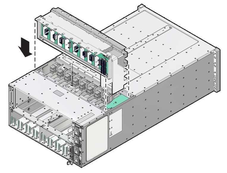
  2. Align and position the replacement midplane assembly in the opening in the top of the server.
  3. Carefully lower the midplane assembly into the server until the top of the assembly is flush with the top of the server.

    Take care not to damage the cables and connectors when lowering the midplane assembly into the server.


    Image showing the midplane assembly lifted out of the server.
  4. Connect the five cables to the connectors on the back of the midplane assembly.

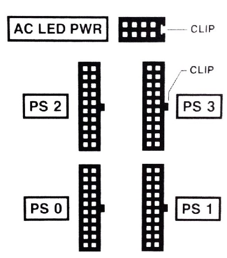
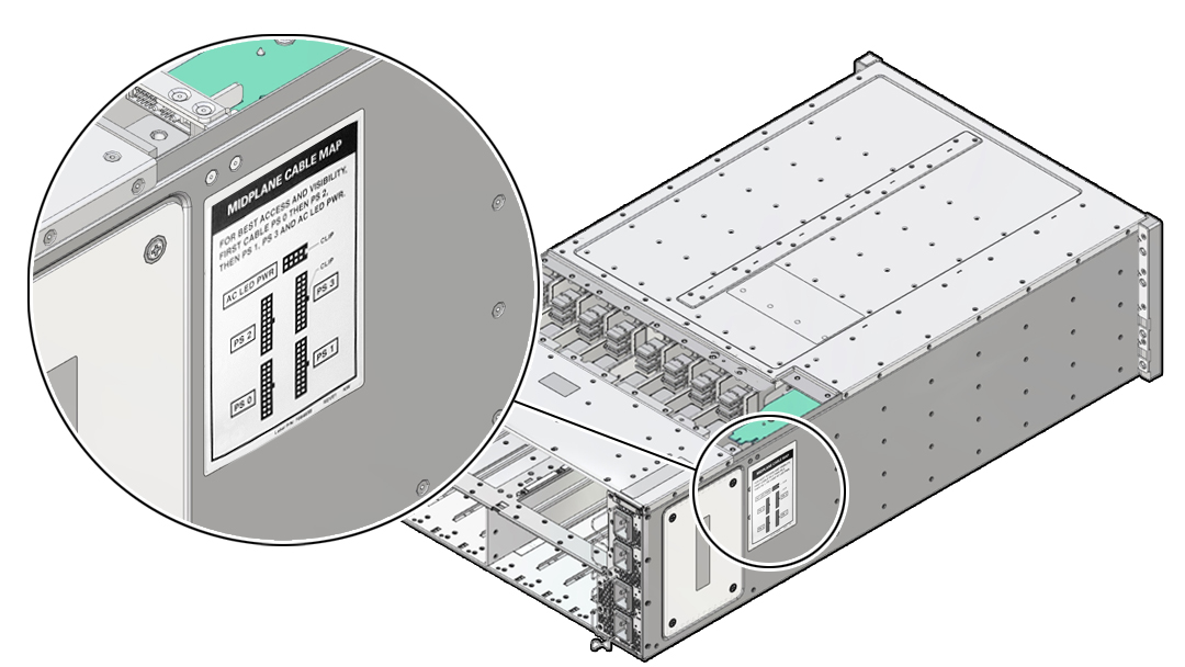
    Ensure that the connectors are positioned correctly, so the key (protrusion) on the side of the connector is aligned with the notch in the connector on the midplane assembly. For best access and visibility, first attach the cable labeled PS 0, then PS 2, followed by PS 1, and finally PS 3. Attach the cable for the AC power indicator board last.


    Image showing side panel label.

    The following illustration shows the label.


    Image showing side panel label
  5. Position the side access cover at the access opening, ensuring that the four captive screws are aligned with the holes in the side of the chassis.
  6. To secure the side access cover to the chassis, tighten the four captive screws.
  7. Install the black plastic insert over the top of the midplane assembly.

    Ensure that the orientation of the insert is correct. The insert is fitted to the opening using tabs and flaps.

  8. Align the top access cover with the opening in the top of the chassis.
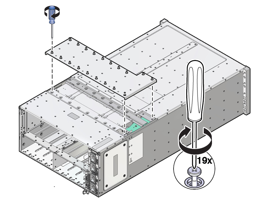
  9. To secure the top access cover to the chassis, tighten the 19 captive screws.

    Image showing the midplane assembly lifted out of the server.
  10. Install the server chassis in the rack.

    Refer to Installing the Server Into a Rack in Oracle Server X8-8 Installation Guide at Oracle Server X8-8 Documentation.

  11. Replace components at the front of the server:
    1. Install the CMODs.
    2. Install both fan frames.
    3. Install all eight fan modules FM0-7.
    4. Install the FIM.
    5. Install the four power supplies PS0-3.
  12. Replace components at the back of the server:
    1. Install both SMODs.
    2. Install all eight DPCCs.

      See Install a DPCC.

      For slot designations, see Replaceable Components.

    3. Attach cables to their respective connectors and ports at back panel of the server.

      Install data cables (DPCC and SMOD) before attaching AC power cables to the AC inlets.

  13. Prepare the server for operation.
  14. Update the TLI FRUPROM data containers.

    Oracle service personnel needs to manually reprogram the FRU containers into FRUPROM0 and FRUPROM1.