Server Boot Process and Normal Operating State Indicators
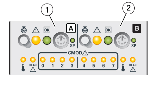
A normal server boot process involves System A (SMOD0) or System B (SMOD1) service processor SP OK indicator and System OK indicator. The following illustration shows SMOD0 System A (callout 1) and SMOD1 System B (callout 2).

| Call Out | System | Activity |
|---|---|---|
|
1 |
System A SMOD0 |
|
|
2 |
System B SMOD1 |
|
The following table describes the indicator activity during a normal boot sequence.
| System Condition | SP Indicator | Power OK Indicator |
|---|---|---|
|
AC power applied to server. SP is booting. |
Blinks |
Off |
|
SP is booted and ready to use. Host is off. |
Steady On |
Blinks at single blink rate (quick flash every 3 seconds) |
|
SP is running. Host is booting. |
Steady On |
Blinks at fast rate |
|
SP and host are running. This is the normal operating state of the system. |
Steady On |
Steady On |