Library Cell Addressing Scheme
Cell addressing designates physical location using Library, Rail, Column, Side, Row (L, R,C,S,W). The GUI onlu uses (C, S, W) to address each location.
- Library
- Always 1.
- Rail
- Always 1.
- Column
- Indicates the horizontal location of a storage cell or drive bay
referenced from the center line:
- Positive (+) value indicates right of center line
- Negative (-) value indicates left of center line
- Zero (0) is never used for a column number. The first column to the right of the center line (viewed from the front of the library) is column 1. The first column to the left of the center line is column -1.
Base Module — Contains columns 1 to 6 for storage cells and 1 to 4 for drive cells.
Drive Module — Contains six columns for storage cells and four for drive bays. Column numbering for storage cells continues consecutively from the adjacent module. Column numbering for drive bays uses the storage cell columns that are closest to zero. For example, a Drive Module immediately to the right of the Base Module will contain storage cell columns 7 through 12 and drive columns 7 through 10. A Drive Module immediately to the left of the Base Module will contain storage cell columns -6 through -1 and drive columns -4 through -1.
Cartridge Module — Contains six columns for storage cells. Column numbering continues consecutively from the adjacent module.
Parking Module — Contains three columns for storage cells. The outer most three columns are inactive. Column numbering continues consecutively from the adjacent module.
Access Module — Contains three columns for storage cells. Column numbering continues from the adjacent module.
- Side
-
- Back wall (drive side) = 1 (B in GUI)
- Front wall (CAP side) = 2 (F in GUI)
- Row
- The vertical location of a storage cell, consecutively numbered top down (1 to 52).
Cell Addressing of Tape Drive Bays
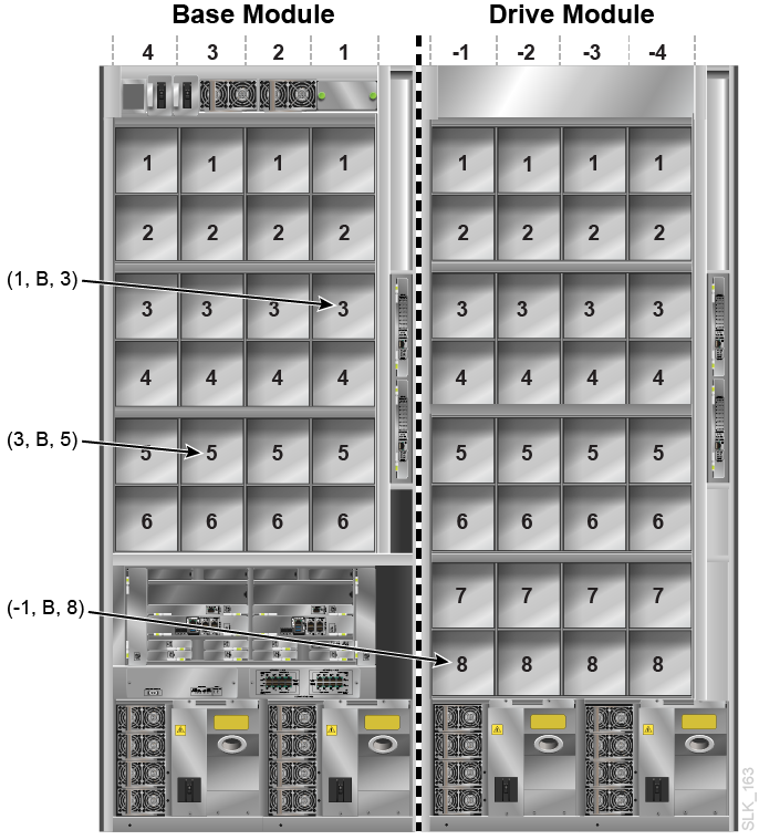
The library addressing distinguishes a drive bay by column and row. The side value is always 1 (shown as B in the GUI).
Figure A-1 Example Library Addressing of Tape Drives (viewed from back of library)

Cell Addressing of Rotational CAP Cell
The CAP cells have a unique addressing scheme.
- Column
-
The CAP column depends on the location of the module containing the CAP. The CAP column value corresponds to the fifth column from the left-side of the module. For example, module number 2 (second module to the right of the Base) will have storage columns 13 through 18 and the rotational CAP column will be 17. Module number -3 (third module to the left of the Base) will have storage cell columns -18 through -13 and the rotational CAP column will be -14.
- Side
-
Always 2 (shown as F in the GUI), since the CAPs are only located on the front of the module.
- Row
-
When addressing a specific cell: the row value is the cell in the CAP magazine (values 1 to 26).
- Example CAP Cell Address
-
For this example, the library has Cartridge Module, Drive Module, Base Module, and all modules have a CAP. The top cell of the Cartridge Module CAP would be (-8, F, 1).