- Oracle ZFS Storage Appliance Cabling Guide, Release OS8.8.x
- Getting Started with Cabling
- Cabling Controllers in a Base Cabinet to Disk Shelves in an Expansion Cabinet
Cabling Controllers in a Base Cabinet to Disk Shelves in an Expansion Cabinet
Use the following procedure to connect controllers in a base cabinet to disk shelves in an expansion cabinet with a 6-meter cable.
- Locate the appropriate cabling diagram for your system in Getting Started with Cabling.
-
In the base cabinet, connect one end of the cable into the appropriate HBA port in the appropriate controller.
Ensure the cable is connected to the correct HBA port. Controller models can differ in regard to vertically oriented or horizontally oriented HBAs, which affects the port order.
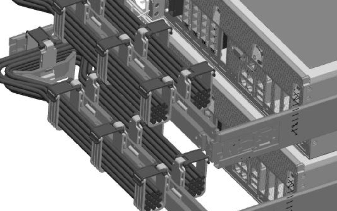
- If the controller has a cable management arm (CMA), route the cable through the CMA, ensuring that there is ample slack for servicing the controller as shown in the following illustration with clustered controllers. If not using a CMA, secure the cable to the rack rail with a cable tie, allowing ample slack for servicing the controller, and so the cable is not bent near its connector.

Note:
Do not route more than 12 copper SAS cables through the CMA. In mixed Oracle Storage Drive Enclosure DE3-24 and Oracle Storage Drive Enclosure DE2-24 disk shelf configurations, up to 4 copper SAS cables can be routed through the CMA. All SAS active optical cables (AOCs) must be routed through the CMA. -
Route the remaining cable so it exits either the top or bottom of the base cabinet and into the corresponding top or bottom entrance of the expansion cabinet.
- Determine the rack exit port (top or bottom). Use a cable tie to attach the cable to the rack hole closest to the rack exit.
- Route the cable into the expansion rack through the appropriate rack cut out. Using a cabling tie, attach the cable to the closest rack hole.
- Routing the cable vertically along the rack rail, use another cable tie to secure the cable close to the disk shelf to which it will be attached.
-
Verify clearance for power supply removal, and then connect the other end of the cable, now in the expansion cabinet, to the appropriate port in the appropriate disk shelf.
Ensure the cable is connected to the correct disk shelf port. Some I/O Modules are oriented upside down in some disk shelf models, which affects the port order.
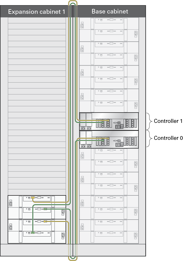
Cabling Controllers in a Base Cabinet to Disk Shelves in an Expansion Cabinet (Oracle ZFS Storage ZS4-4 to Oracle Storage Drive Enclosure DE2-24C shown)

Note:
The illustration above only shows the 6-meter cables connecting from the base cabinet to the expansion cabinet. To cable the rest of the disk shelves, locate the appropriate cabling diagram in the Getting Started with Cabling. -
If there is excessive cable, secure it to the rack rail.
- Create a 12.7-centimeter (5-inch) diameter coil with the excess, allowing ample slack for servicing components and for placing the coil to the side of the disk shelf.
- Secure the coil with a cable tie.
- Slide the coil between the vertical rack rail and the rack side panel, ensuring that the cable tie is facing the rear of the rack.
- Using the cable tie, secure the coil to the rack rail.
- Trim the cable tie excess.
- Repeat steps 2 through 8 to connect the second cable for the disk chain.
-
Repeat this process for any remaining disk shelf chains.
Keep approximately 20.32 centimeters (8 inches) between cable tie-offs on a side.
- Repeat the entire procedure for any additional expansion cabinets.