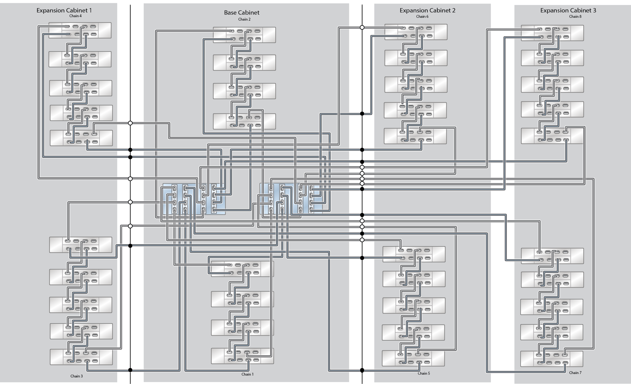
Cabling Tables and Diagrams for Oracle ZFS Storage Appliance Racked System ZS5-4 Capacity Configurations
The following table describes the locations and port connections for two controllers and eight disk shelves in the base cabinet, using 3-meter SAS cables. The first disk shelf is located in RU01, and each disk shelf has two IOMs.
Table 12-2 Base Cabinet: Controller and Disk Shelf Locations and Connections
| FROM | TO | ||||
|---|---|---|---|---|---|
|
RU |
CONTROLLER |
HBA PORT |
RU |
DISK SHELF |
DISK SHELF PORT |
|
20 |
1 |
Slot 3, Port 0 |
1 |
1 |
IOM 1, Port 2 |
|
17 |
0 |
Slot 6, Port 0 |
1 |
1 |
IOM 0, Port 2 |
|
20 |
1 |
Slot 7, Port 0 |
23 |
3 |
IOM 1, Port 2 |
|
17 |
0 |
Slot 9, Port 0 |
23 |
3 |
IOM 0, Port 2 |
|
17 |
0 |
Slot 3, Port 0 |
5, 13 |
2, 6 |
IOM 1, Port 0 |
|
20 |
1 |
Slot 6, Port 0 |
5, 13 |
2, 6 |
IOM 0, Port 0 |
|
17 |
0 |
Slot 7, Port 0 |
27, 35 |
4, 8 |
IOM 1, Port 0 |
|
20 |
1 |
Slot 9, Port 0 |
27, 35 |
4, 8 |
IOM 0, Port 0 |
The following table describes the locations and port connections for 10 disk shelves in Expansion Cabinet 1, using 6-meter SAS cables. The first disk shelf is located in RU01, and each disk shelf has two IOMs. Expansion Cabinet 1 supports disk shelves 9 through 18.
Table 12-3 Expansion Cabinet 1: Controller and Disk Shelf Locations and Connections
| FROM | TO | ||||
|---|---|---|---|---|---|
|
RU |
CONTROLLER |
HBA PORT |
RU |
DISK SHELF |
DISK SHELF PORT |
|
20 |
1 |
Slot 3, Port 1 |
1 |
9 |
IOM 1, Port 2 |
|
17 |
0 |
Slot 6, Port 1 |
1 |
9 |
IOM 0, Port 2 |
|
20 |
1 |
Slot 7, Port 1 |
21 |
11 |
IOM 1, Port 2 |
|
17 |
0 |
Slot 9, Port 1 |
21 |
11 |
IOM 0, Port 2 |
|
17 |
0 |
Slot 3, Port 1 |
5, 9, 13, 17 |
10, 13, 14, 17 |
IOM 1, Port 0 |
|
20 |
1 |
Slot 6, Port 1 |
5, 9, 13, 17 |
10, 13, 14, 17 |
IOM 0, Port 0 |
|
17 |
0 |
Slot 7, Port 1 |
25, 33, 37 |
12, 16, 18 |
IOM 1, Port 0 |
|
20 |
1 |
Slot 9, Port 1 |
25, 33, 37 |
12, 16, 18 |
IOM 0, Port 0 |
The following table describes the locations and port connections for 10 disk shelves in Expansion Cabinet 2, using 6-meter SAS cables. The first disk shelf is located in RU01, and each disk shelf has two IOMs. Expansion Cabinet 2 supports disk shelves 19 through 28.
Table 12-4 Expansion Cabinet 2: Controller and Disk Shelf Locations and Connections
| FROM | TO | ||||
|---|---|---|---|---|---|
|
RU |
CONTROLLER |
HBA PORT |
RU |
DISK SHELF |
DISK SHELF PORT |
|
20 |
1 |
Slot 3, Port 2 |
1 |
19 |
IOM 1, Port 2 |
|
17 |
0 |
Slot 6, Port 2 |
1 |
19 |
IOM 0, Port 2 |
|
20 |
1 |
Slot 7, Port 2 |
21 |
21 |
IOM 1, Port 2 |
|
17 |
0 |
Slot 9, Port 2 |
21 |
21 |
IOM 0, Port 2 |
|
17 |
0 |
Slot 3, Port 2 |
5, 9, 13, 17 |
20, 23, 24, 27 |
IOM 1, Port 0 |
|
20 |
1 |
Slot 6, Port 2 |
5, 9, 13, 17 |
20, 23, 24, 27 |
IOM 0, Port 0 |
|
17 |
0 |
Slot 7, Port 2 |
25, 33, 37 |
22, 26, 28 |
IOM 1, Port 0 |
|
20 |
1 |
Slot 9, Port 2 |
25, 33, 37 |
22, 26, 28 |
IOM 0, Port 0 |
The following table describes the locations and port connections for 10 disk shelves in Expansion Cabinet 3, using 6-meter SAS cables. The first disk shelf is located in RU01, and each disk shelf has two IOMs. Expansion Cabinet 2 supports disk shelves 29 through 38.
Table 12-5 Expansion Cabinet 3: Controller and Disk Shelf Locations and Connections
| FROM | TO | ||||
|---|---|---|---|---|---|
|
RU |
CONTROLLER |
HBA PORT |
RU |
DISK SHELF |
DISK SHELF PORT |
|
20 |
1 |
Slot 3, Port 3 |
1 |
29 |
IOM 1, Port 2 |
|
17 |
0 |
Slot 6, Port 3 |
1 |
29 |
IOM 0, Port 2 |
|
20 |
1 |
Slot 7, Port 3 |
21 |
31 |
IOM 1, Port 2 |
|
17 |
0 |
Slot 9, Port 3 |
21 |
31 |
IOM 0, Port 2 |
|
17 |
0 |
Slot 3, Port 3 |
5, 9, 13, 17 |
30, 33, 34, 37 |
IOM 1, Port 0 |
|
20 |
1 |
Slot 6, Port 3 |
5, 9, 13, 17 |
30, 33, 34, 37 |
IOM 0, Port 0 |
|
17 |
0 |
Slot 7, Port 3 |
25, 33, 37 |
32, 36, 38 |
IOM 1, Port 0 |
|
20 |
1 |
Slot 9, Port 3 |
25, 33, 37 |
32, 36, 38 |
IOM 0, Port 0 |
The following diagrams illustrate how pre-racked systems are cabled, as well as how to expand your system in the future. The legend for each diagram is as follows:
-
A hollow circle indicates the cable connection to the top IOM (IOM 1).
-
A solid circle indicates the cable connection to the bottom IOM (IOM 0).
10 Oracle Storage Drive Enclosure DE3-24C Disk Shelves
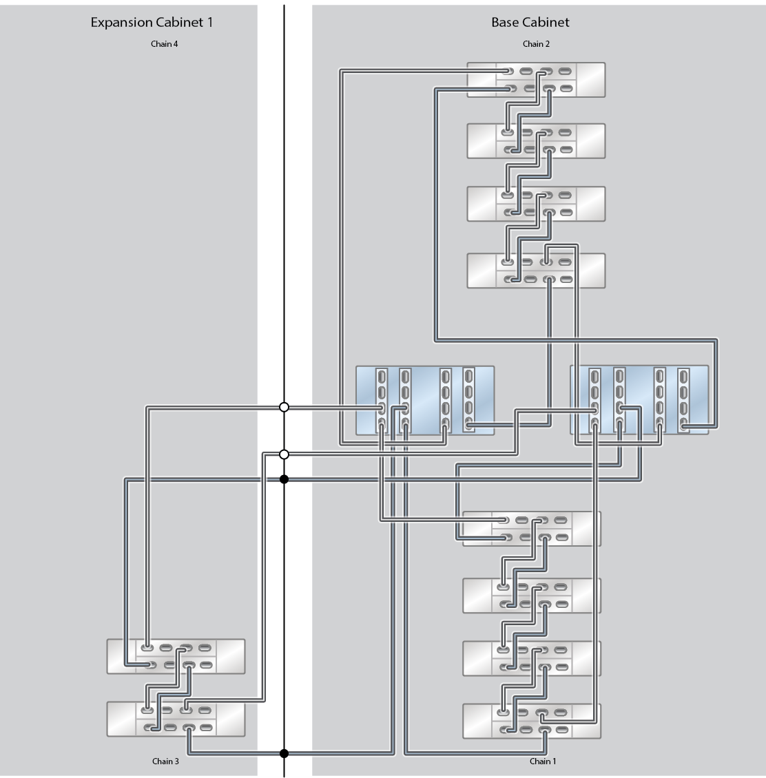
12 Oracle Storage Drive Enclosure DE3-24C Disk Shelves
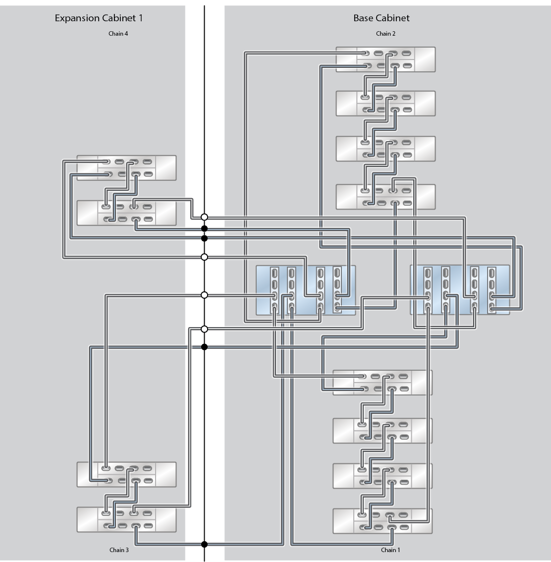
13 Oracle Storage Drive Enclosure DE3-24C Disk Shelves (Half Rack)
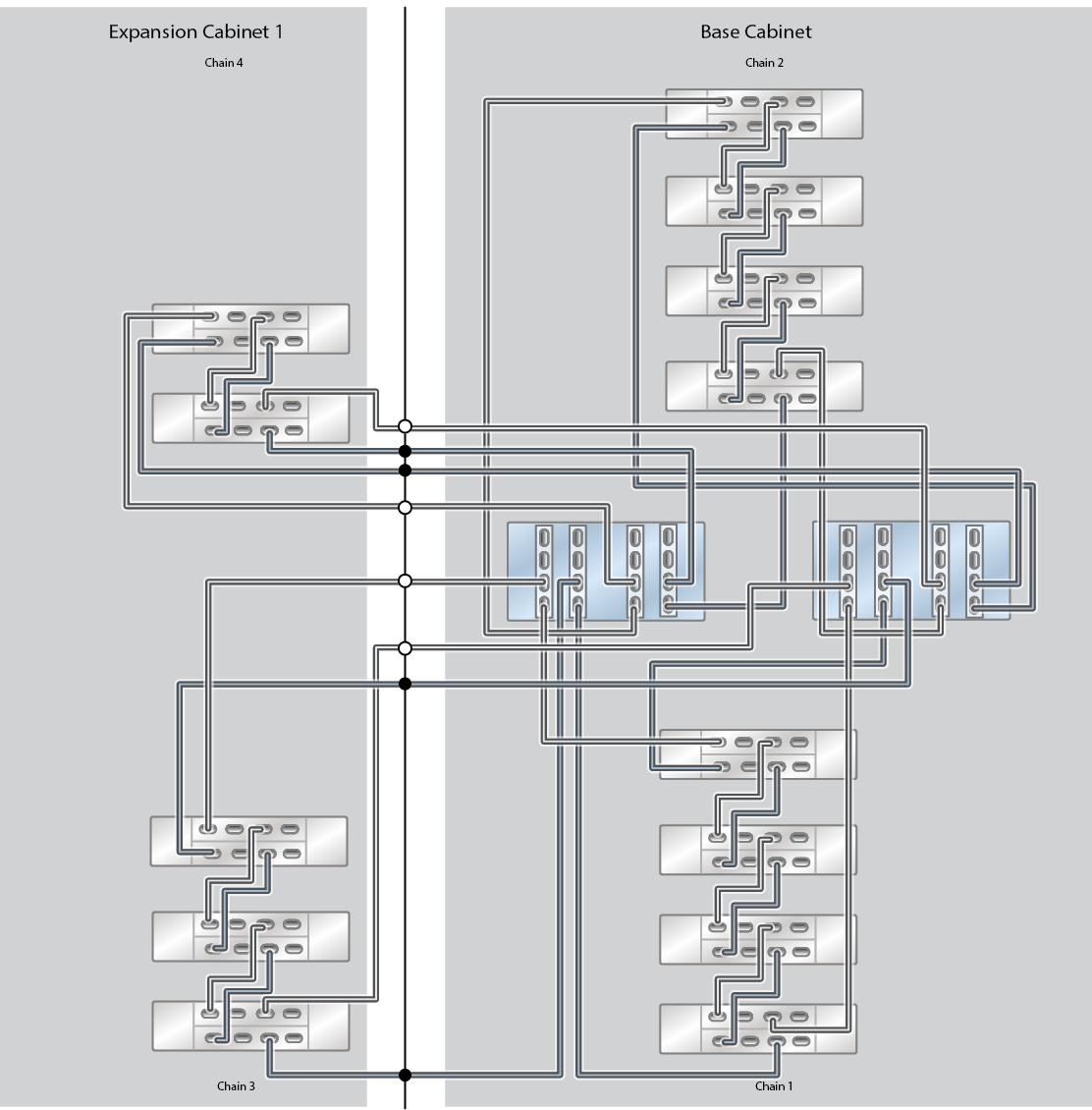
14 Oracle Storage Drive Enclosure DE3-24C Disk Shelves
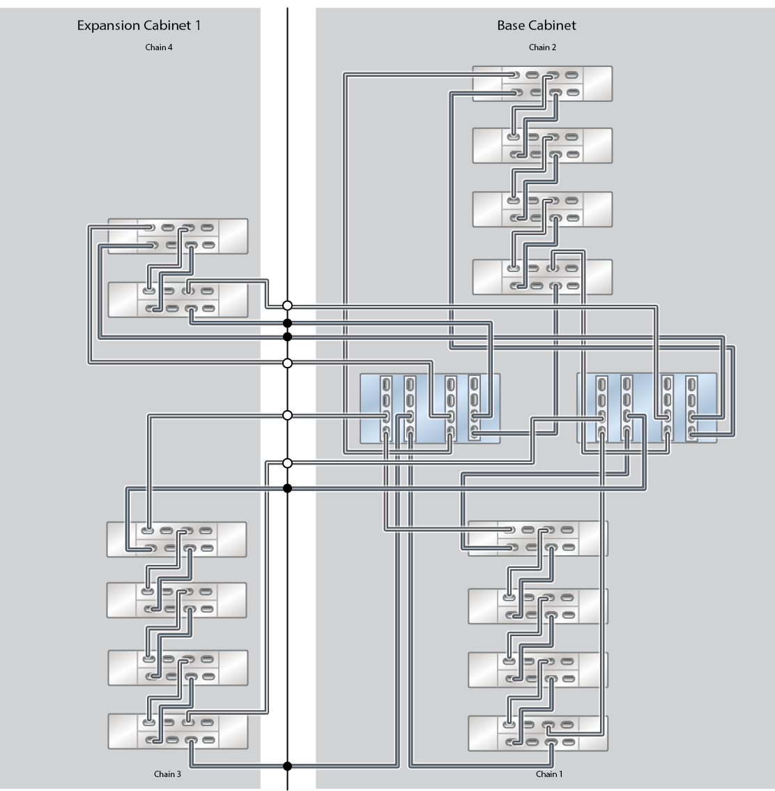
16 Oracle Storage Drive Enclosure DE3-24C Disk Shelves
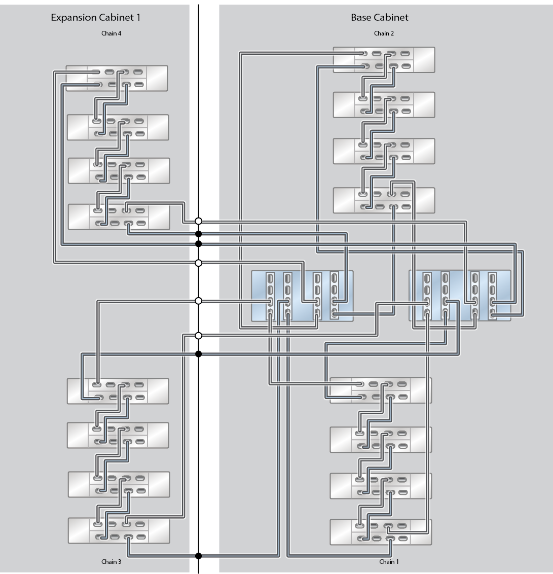
18 Oracle Storage Drive Enclosure DE3-24C Disk Shelves
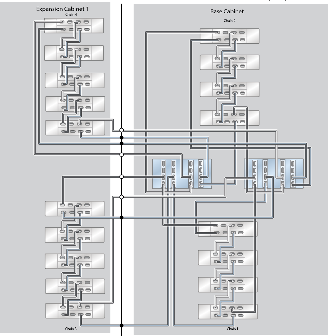
20 Oracle Storage Drive Enclosure DE3-24C Disk Shelves
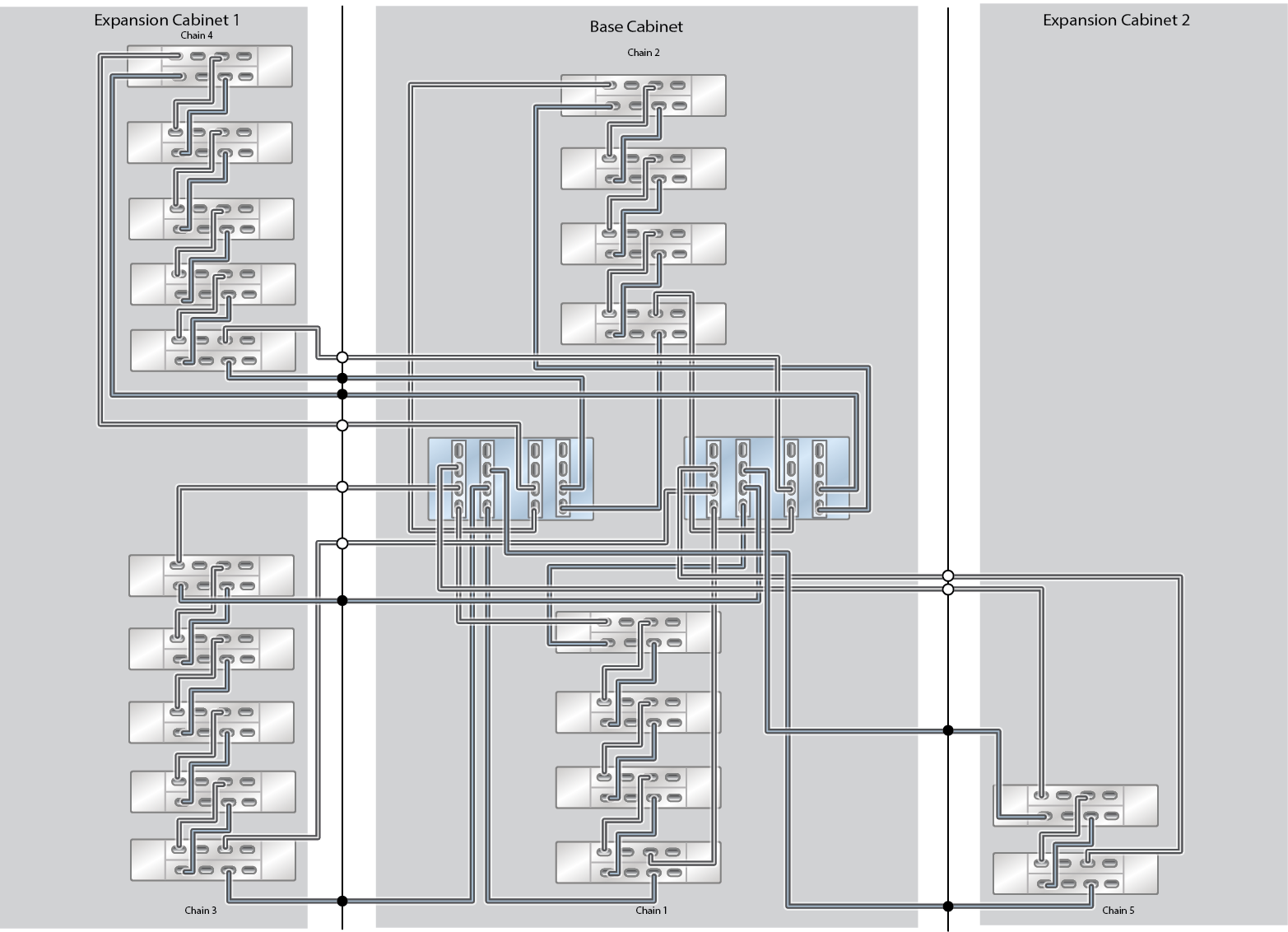
22 Oracle Storage Drive Enclosure DE3-24C Disk Shelves
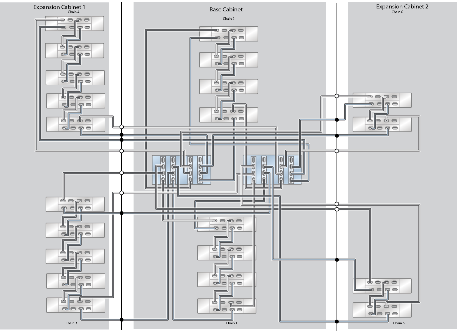
23 Oracle Storage Drive Enclosure DE3-24C Disk Shelves (Half Rack)
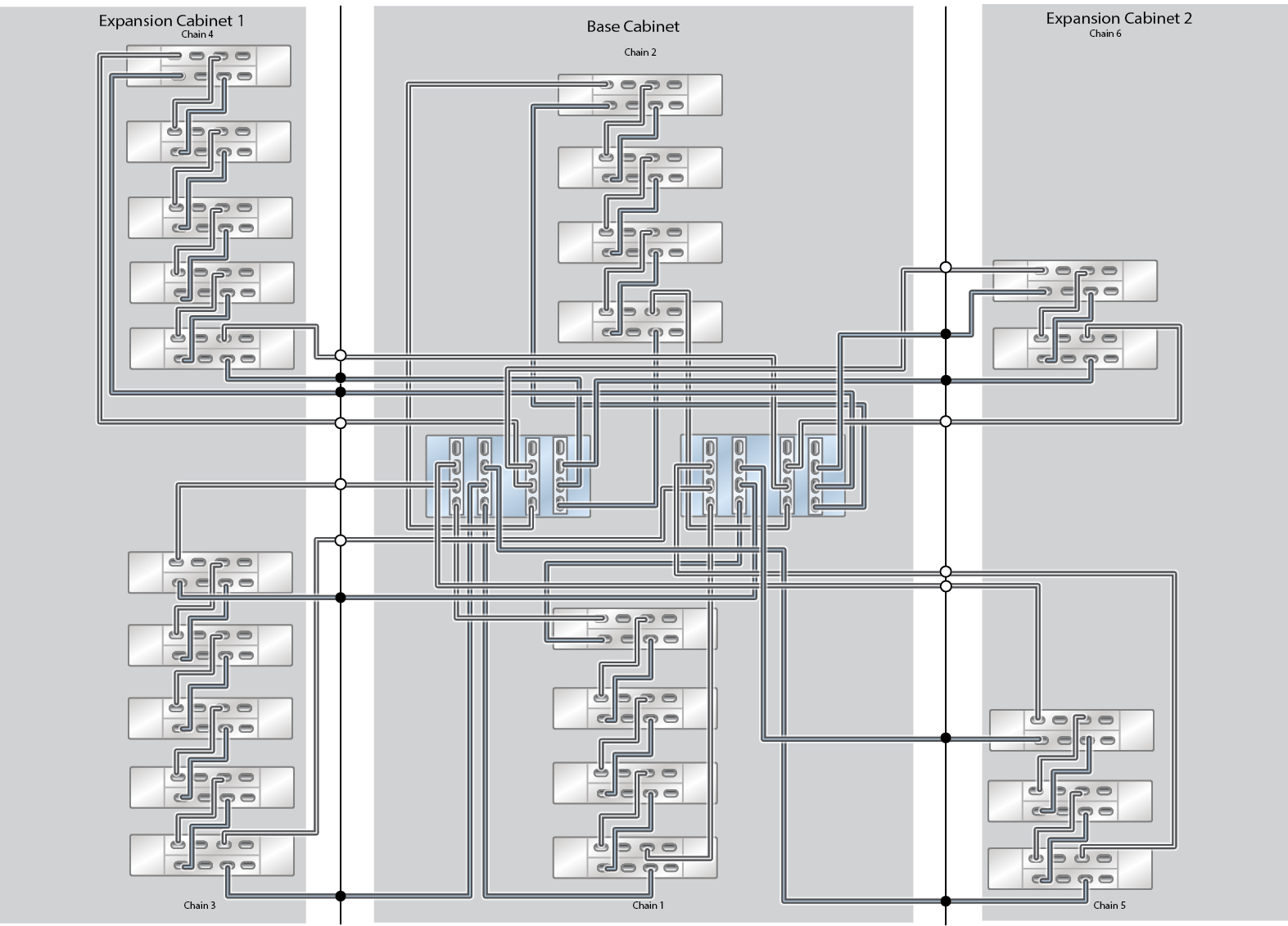
24 Oracle Storage Drive Enclosure DE3-24C Disk Shelves
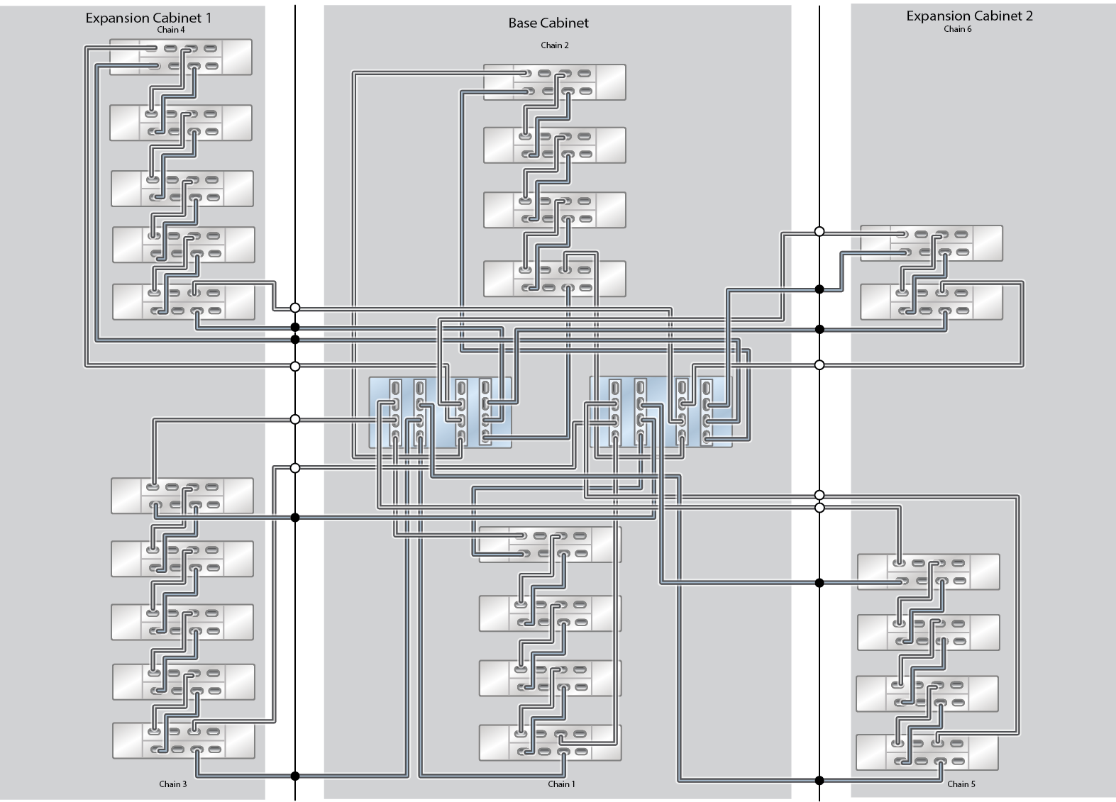
26 Oracle Storage Drive Enclosure DE3-24C Disk Shelves
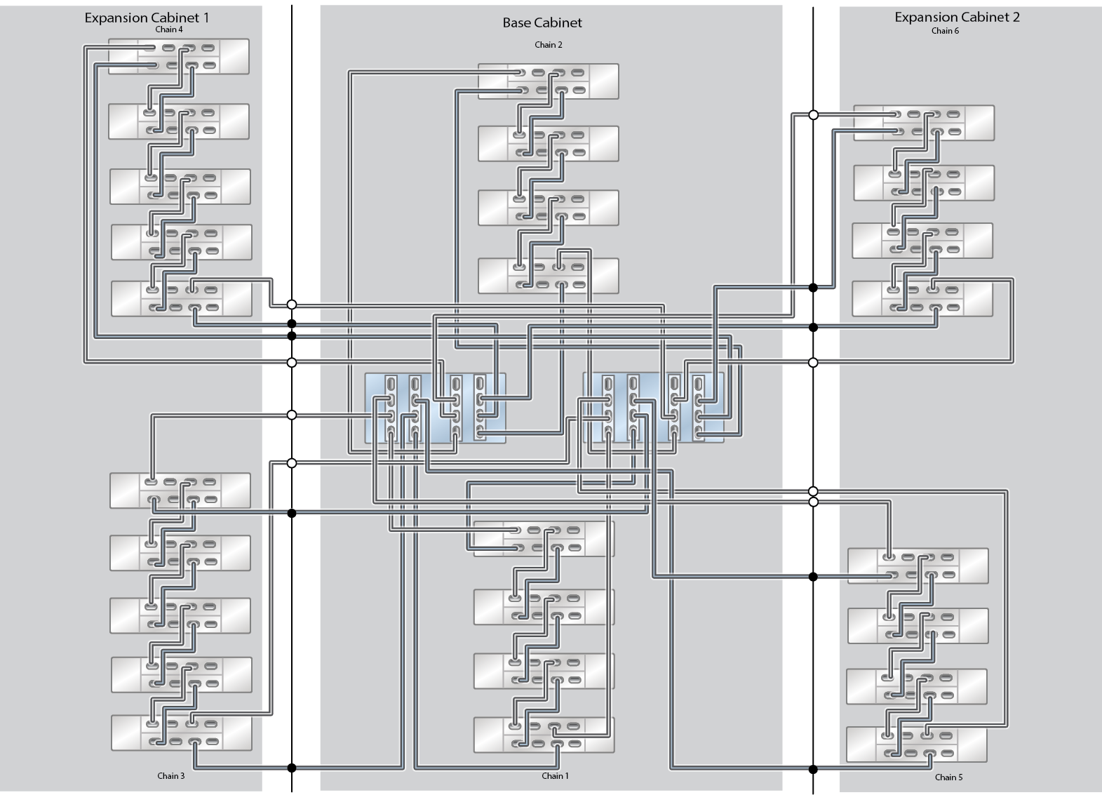
28 Oracle Storage Drive Enclosure DE3-24C Disk Shelves
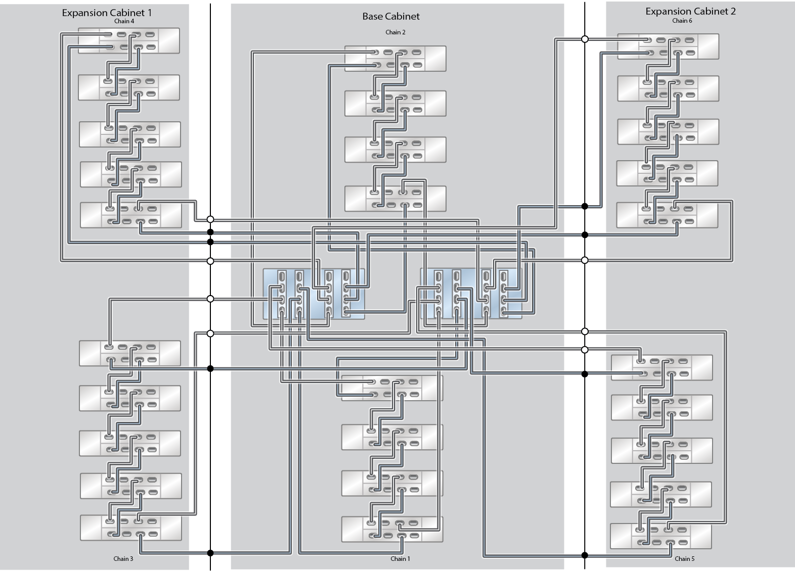
30 Oracle Storage Drive Enclosure DE3-24C Disk Shelves
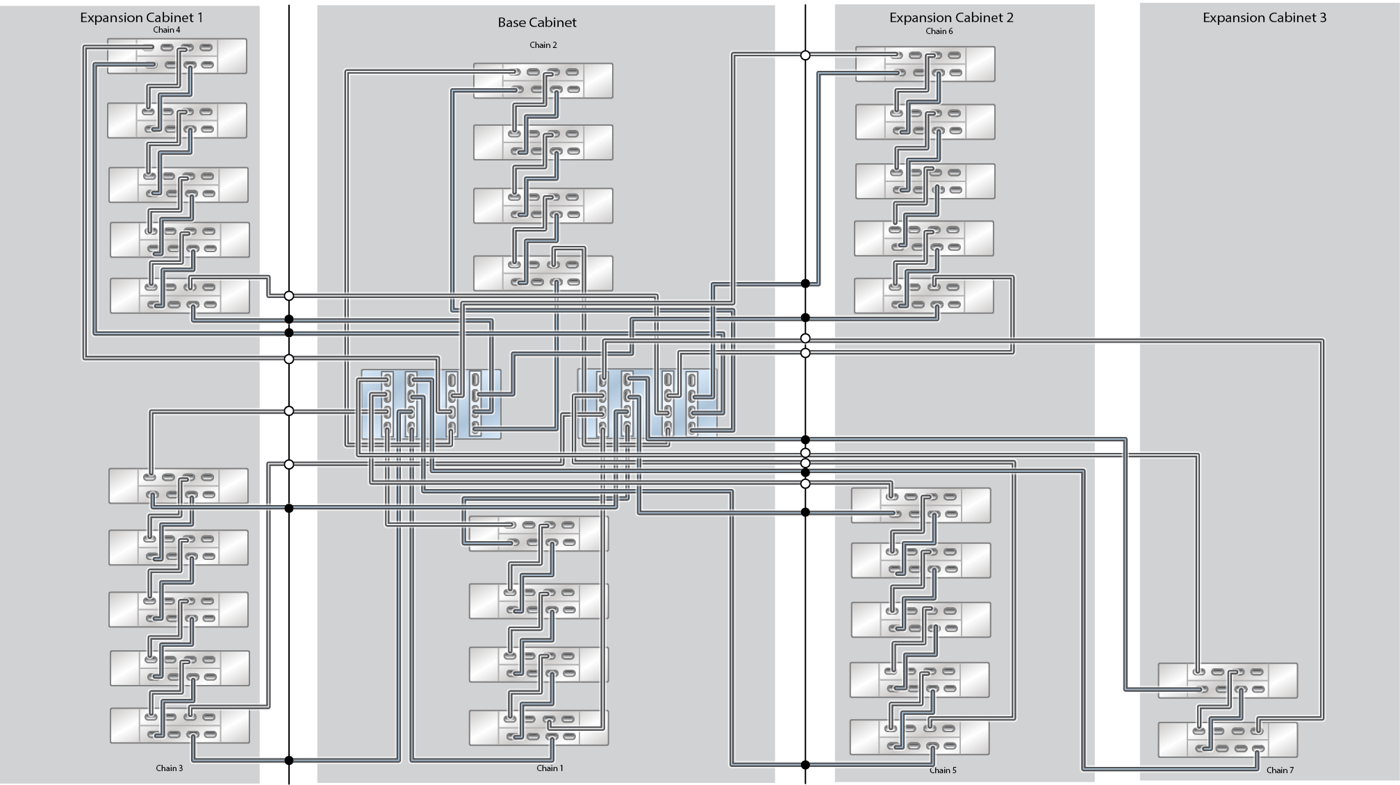
32 Oracle Storage Drive Enclosure DE3-24C Disk Shelves
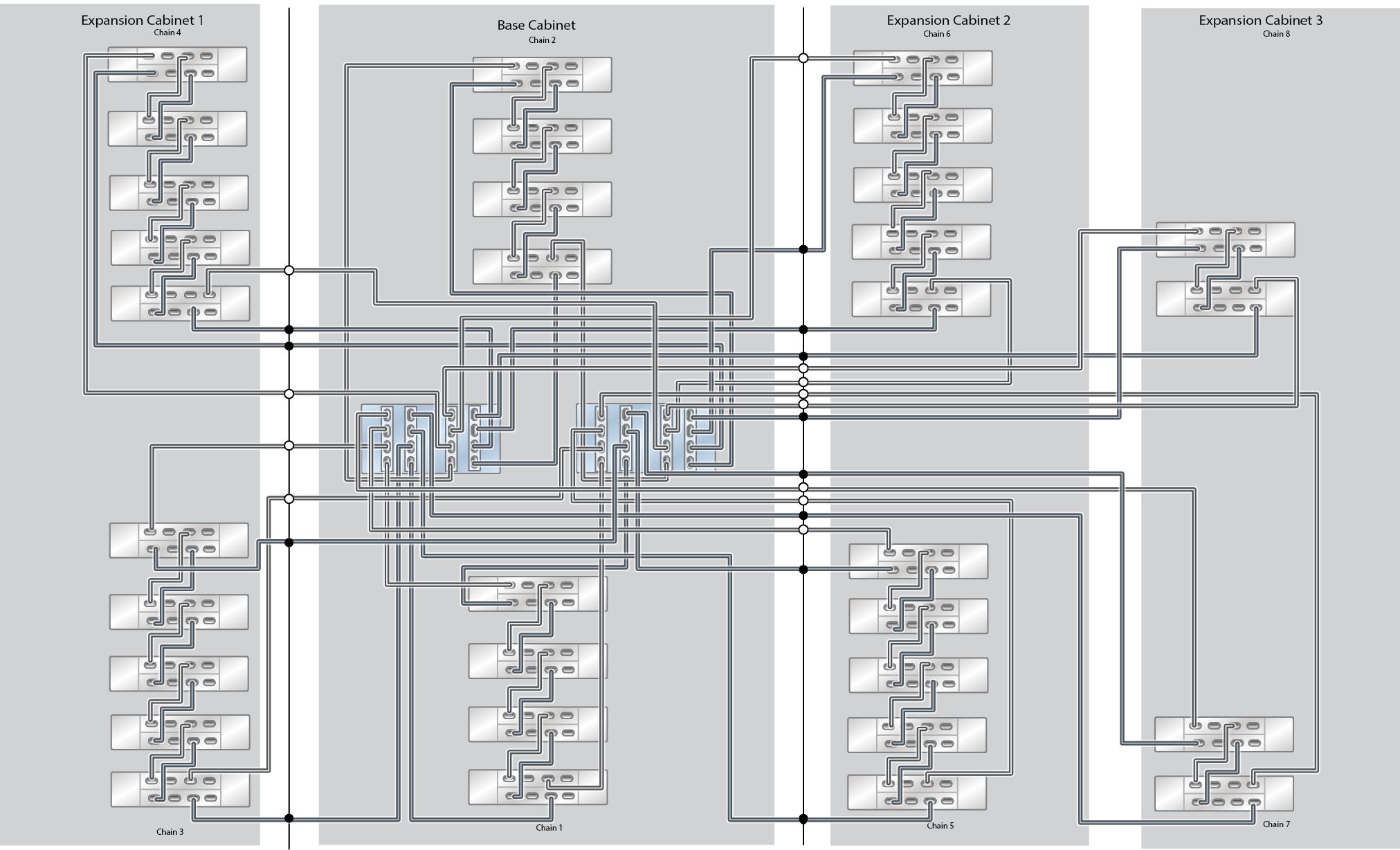
33 Oracle Storage Drive Enclosure DE3-24C Disk Shelves (Half Rack)
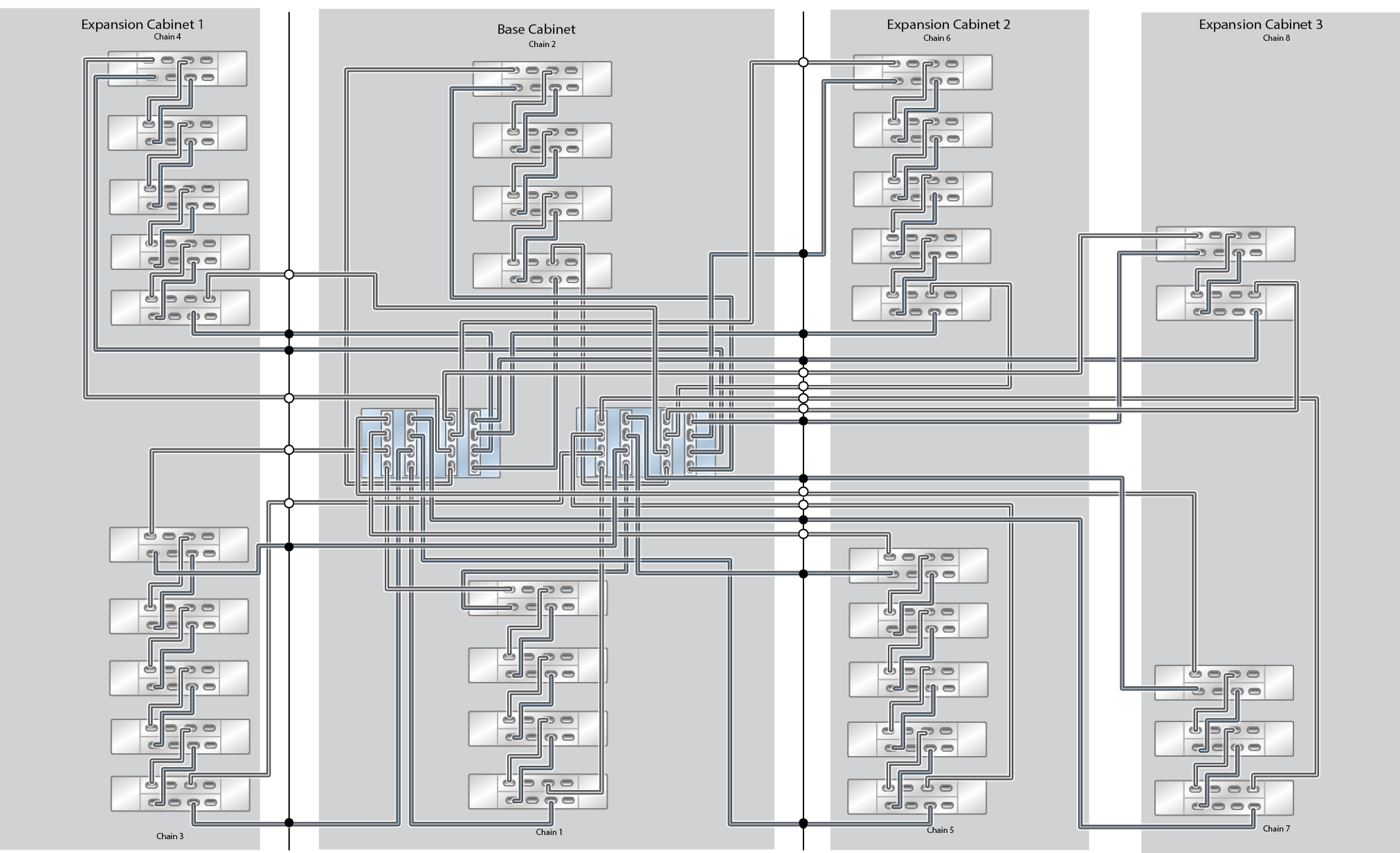
34 Oracle Storage Drive Enclosure DE3-24C Disk Shelves
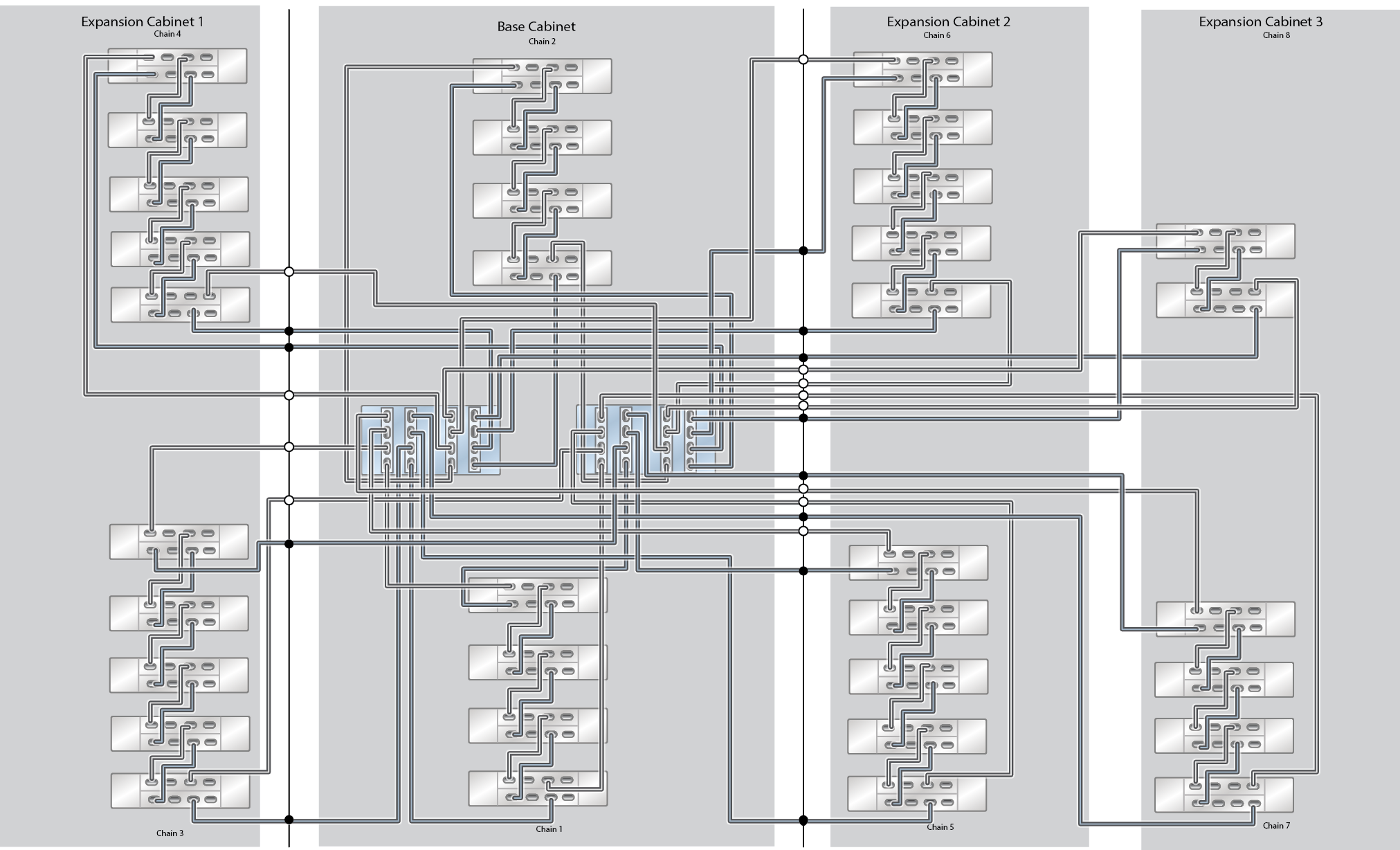
36 Oracle Storage Drive Enclosure DE3-24C Disk Shelves
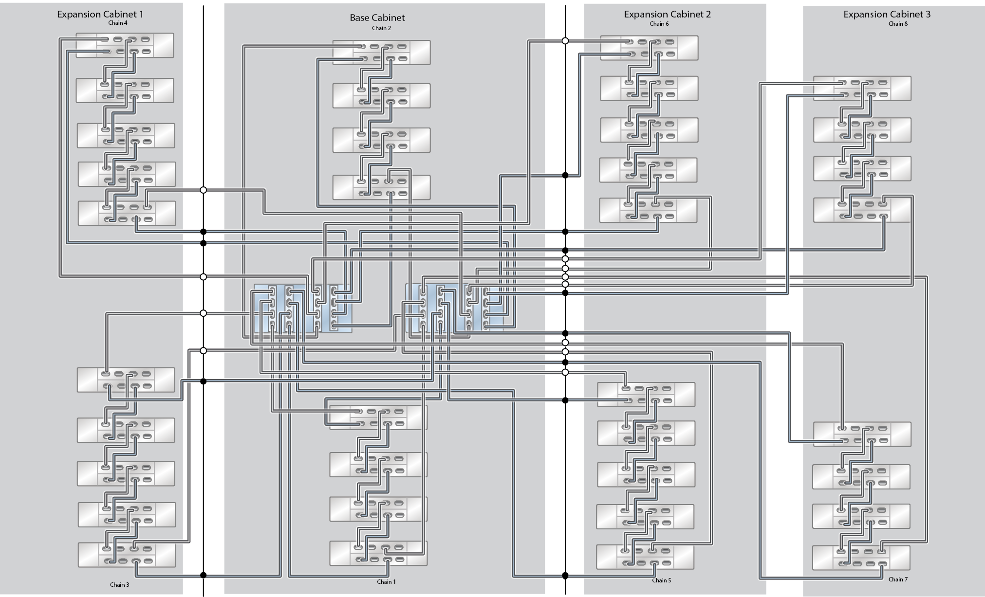
38 Oracle Storage Drive Enclosure DE3-24C Disk Shelves
