3 Configure the Interchange Mapping Utility
This chapter provides information on configuring and mapping the web-based Argus Interchange.
3.1 Navigate to Interchange Mapping
To navigate to the Interchange Mapping menu:
-
Open Argus Console.
-
Go to System Configuration ->Interchange Mapping.
3.2 Message and Acknowledgement Profiles
Argus Interchange Mapping provides the following standard Message and Acknowledgement profiles:
-
ICH-ICSR V2.1 MESSAGE TEMPLATE
-
ICH-ICSR V2.1 MESSAGE TEMPLATE - EMA
-
ICH-ICSR V2.1 MESSAGE TEMPLATE - FDA
-
ICH-ICSR V3.0 MESSAGE TEMPLATE
-
ICH-ICSR V3.0 MESSAGE TEMPLATE - EMA
-
ICH-ICSR V3.0 ACKNOWLEDGMENT TEMPLATE – EMA
-
ICH-ICSR V1.1 ACKNOWLEDGEMENT TEMPLATE
-
ICH-ICSR V1.1 ACKNOWLEDGEMENT TEMPLATE - EMA
-
ICH-ICSR V1.1 ACKNOWLEDGEMENT TEMPLATE - FDA
-
CBER EVAERS V1.0 MESSAGE TEMPLATE
-
CDRH eMDR V1.0 MESSAGE TEMPLATE
Import profiles for EMA & PMDA E2B (R3)
Two new Import profiles for EMA & PMDA E2B (R3) are now available.
-
A new EMA (R3) profile with OOTH Export and Import mappings with all standard features such as Copy, Edit, Print and Audit.
-
A new EMA (R3) acknowledgement with default mappings and with all standard features such as Copy, Edit, Print and Audit.
All conformance rules are added to the OOTB EMA (R3) profile.
Low level Ack generation is supported for EMA (R3) import using physical media.
3.3 Manage Profiles
This section provides information about working with profiles and includes discussions of the following:
-
Defining a Profile
-
Printing a Profile
-
Copying a Profile
-
Deleting a Profile
3.3.1 Define a Profile
This section describes viewing or modifying the rules of a profile in the Interchange Mapping. You can view profile details by selecting a Profile from the Interchange Mapping screen.
On selecting a Profile from the drop-down, the system displays the following information:
-
The tree view structure of ICSR elements
-
The Transmit and Receive tabs
The following notes are displayed at the bottom of the screen:
-
When a profile provided as part of the factory data is selected, * Profile Type is TEMPLATE. All Fields are Read-only.
-
When a custom profile is selected, * Profile Type is User DEFINED. Fields with white background are editable.
3.3.1.1 Use the Transmit Tab
Use the following procedure to view details on the Transmit Tab:
-
Select a profile from the Profile drop-down list.
-
Click Transmit.
The following table lists and describes fields on the Transmit tab:
| Item | Description |
|---|---|
| Adverse Event Database Select Statement | Enables you to enter and view the SQL logic used to extract the value of the selected element of the profile from the AE database. |
| ICSR check checkbox | Indicates whether the selected profile is used in the ICSR check functionality in Argus.
The ICSR check function validates E2B reports based on the validation rules defined for the profiles. Only profiles that have the ICSR checkbox selected are used for validation. |
| Blind in PMDA AE Paper Report | Select this check box if the selected profile must be blind in the PMDA AE Paper Report.
This check box is available only for PMDA E2B R2 Profiles for Japanese user and if the Japanese version is enabled. |
| Configured Transmit Logic | This drop-down lists the descriptive names (alphabetical order) for all the configured Transmit Mapping logic for the particular element across all the HL7 based ICSR profiles. The first value is blank and the last value is (Add New). This drop-down value is available for editing for all custom profiles and is read-only for OOTB Template profile. |
3.3.1.2 Use the Conformance Rules Tab
The Conformance Rules tab is available to the users for the E2B (R3) and PMDA E2B (R3) profiles. The Japanese DTD tab is not available to PMDA E2B (R3).
The tab allows user to configure the following parameters against each ICSR Element node for which data is transmitted (as it is applicable only for E2B export logic). It is available only for the ICSR Element Nodes (except for the Message & Batch Header tags - N) for which data is transmitted and is not available for parent element, as the attributes specific to validations are applicable only at root element level.
This configuration remains un-editable (read only) for all out-of-the-box E2B (R3) based ICSR template profiles (EMA, PMDA) but is allowed to be edited for custom/copied profiles. (The configuration data for out-of-the-box mapping profiles is available with the mapping of that profile).
The Conformance Rules tab data is also copied to the new profile when user copies any existing ICSR profile.
Editing Conformance rules is allowed only for custom profiles.
The following is the Conformance Tab for PMDA profile:
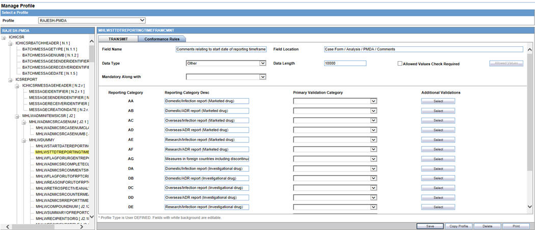
To configure the validations rule against the ICSR element, following fields have been made available to user under the Conformance Rules tab:
| Field | Type | Description |
|---|---|---|
| Field Name / Field Name (J) | Textbox
Length:255 AN |
Field Name/Label of the Case form or Console UI field to which the element's mapping logic corresponds to is specified in this field.
EMA: English PMDA: Japanese For PMDA E2B (R3): Refer Mapping xls > Mapping(Sheet) > UI Field Name(J) |
| Field Location | Textbox
Length:255 AN |
UI Fields Location/path of the Case form or Console UI field to which the element's mapping logic corresponds to is specified in this field.
EMA: English PMDA: Japanese For PMDA E2B (R3): Refer Mapping xls > Mapping (Sheet) > UI Field Name(J) |
| Data Type | Drop-down list | This drop-down list has the following options in the below specified order:
Blank (Default) Country Date/Time E2B Code MedDRA Term/Code MedDRA Version Text For PMDA E2B (R3): Refer Mapping xls > Mapping(Sheet) > PMDA Data Type DTD (R3) |
| Data Length | Textbox
Length: 9 chars |
This text box allows user to enter only Numeric Values
For PMDA E2B (R3): Refer Mapping xls > Mapping(Sheet) > PMDA Length DTD (R3) |
| Mandatory Along with | Drop-down list | This drop-down list contains the DTD_ELEMENT names that are present under the same parent of the selected element (except the selected element itself), with blank as the first and the default option
Format: DTD_ELEMENT(DATA_ELEMENT) Display Order: Same as they are listed in the Element navigation tree on the left For PMDA E2B (R3): Refer Mapping xls > Mapping(Sheet) > Mandatory Along with |
| Allowed Value Check Required | Checkbox | This checkbox is left unchecked by default
For PMDA E2B (R3): Refer Mapping xls > Mapping(Sheet) > Allowed Values |
| Allowed Values | Button | Clicking this button opens up Allowed value configuration Dialog for configuring the allowed values for the selected elements against that profile
This button is enabled only if Allowed Value Check Required checkbox is checked For PMDA E2B (R3): Refer Mapping xls > Mapping (Sheet) > Allowed Values |
| Primary Validation Category | Drop-down list | This drop-down list is available for EMA profiles only.
The following option is listed in the drop-down list in the below specified order: Blank (Default) Mandatory Conditional Mandatory Do not enter Other Fatal Validation Optional |
| Additional Validations | Button | On clicking this button Additional Validation Configuration Dialog opens up, this Dialog enables users to configure the SQL based validations for the element.
This button is available for EMA. |
| PMDA Specific | ||
| Reporting Category | Label | All Reporting Category (R3) Codes (AA, AB, AC, AD, AE, AF, AG, DA, DB, DC, DD, DE, DF, DG, BC, BD) as configured in the Reporting_category (flex code list) are listed here, along with Nullification. |
| Reporting Category Description | Label | Description of the corresponding Reporting Category is listed here. |
| Primary Validation Category | Drop-down list | This drop-down list is available for PMDA profile only.
The following option is listed in the drop-down list in the below specified order: Blank (Default) Mandatory Mandatory for Completion Report Conditional Mandatory for Completion Report Conditional Mandatory Do not Enter Other Fatal Validation Optional For PMDA E2B (R3): Refer Mapping xls > Mapping (Sheet) > Reporting Category wise Conformance |
| Additional Validations | Button | On clicking this button Additional Validation Configuration, the Dialog opens. This Dialog enables users to configure the SQL based validations for the element.
Available button available against each Reporting Category. |
| Save | Button | On clicking the Save button, the changes are committed to Data base and audit logged.
This committing of data includes any changes done in the Allowed Value Configuration and Additional Validation Configuration Dialogs as well. On clicking the Save button, the application logic validates that there exists a Primary category for the ICSR Element
If there exists a row with primary category as blank, the application displays an error message: Please select a Primary Validation category for the element Title: ICSR Validation with OK Button. |
| Button | On clicking the print button, the application prints all the Conformance rule tab data. |
The Allowed Values Configuration Dialog
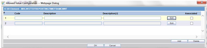
On clicking Allowed Values, the Allowed Values Configuration Dialog (modal Dialog) opens. The Allowed Values Configuration Dialog lets users View, Add, Update, Delete and Associate/De-associate the Codes and Description attribute of the Allowed values for the particular ICSR element for that profile.
Description for fields/buttons on the Allowed Values Configuration Dialog:
Table 3-1 Allowed Values Configuration Dialog fields
|
Code textbox |
This is a textbox where user enters the Code value that is being transmitted in the ICSR report. For example, E2B R3 Codes, ISO code and so on. |
|
Description textbox |
This is a textbox where user enters the description against the Code that is being transmitted in the ICSR report. |
|
Description (J) textbox |
This is a textbox where user enters the Japanese description against the Code that is being transmitted in the ICSR report. This is visible only to J user (when J module is enabled) and only for PMDA Profile |
|
Edit button |
On clicking the edit button, the Code and Description textboxes become enabled for user to edit |
The Additional Validation Configuration Dialog
Clicking Additional Validations displays the Additional Validation Configuration Dialog which lets the user View, Add, Update, Delete, Associate/De-associate, categorize and mark a validation to be Primary for the ICSR element of that profile.
If user marks any validation as Primary, the Associated drop-down list is disabled by default.
On unchecking the Primary Validation checkbox, the Primary validation checkbox for all other validations and the Associate and Validation Category drop-down lists for this particular validation are enabled.
For EMA profiles, the Additional Validation can be configured at the element level, whereas for the PMDA profile the validation can be configured individually against each reporting category for that element.
The OOTB validations are only allowed to be Associate, Disassociate, categorized or marked as primary for the element, and the Edit button always remains disabled for all such OOTB validations.
Description for fields/buttons on the Additional Values Configuration Dialog:
Table 3-2 Additional Values Configuration Dialog fields
|
Message Text area |
In this text area, the user specifies the message that is printed in the validation report in case of a failure validation. |
|
Message (J) Text area |
In this text area, the user specifies the Japanese message that is printed in the validation report in case of a failure validation. This is visible only to J user (when J module is enabled) and only for PMDA Profile. |
|
Validation SQL Text area |
In this text area, the user specifies the SQL condition for the validation that is executed in order to run this particular validation. |
|
Edit button |
On clicking the edit button, the Message and Validation SQL text areas becomes enabled for user to edit. |
|
Associate Drop-down list |
Lets the user associate or de-associate the allowed value for an element for the profile and has the following set of values: (R3) profiles that supports both Export & Import, that is, EMA (R3) a. Blank (Validation not associated with this profile) b. Transmit (Validation only applicable during export) c. Receive (Validation only applicable during Import) d. Transmit & Receive (Validation applicable for both Export & Import) (R3) profiles that support Export but do not support the Import a. Blank (Validation not associated with this profile) b. Transmit (Validation only applicable during export) |
|
Validation Category |
User specifies the category of validation by selecting an option from this drop-down list. |
|
Primary Validation checkbox |
User marks a validation as primary validation against an element for the profile by checking this checkbox. |
|
Add button |
On clicking the Add button, a new row is added to the grid, with Message, Description text areas, Associate drop-down list and Validation Type drop-down list (blank) enabled by default. |
|
Delete button |
Deleted button is disabled by default, and is enabled only if user selects a user created custom validations row in the grid. |
3.3.1.3 Use the Receive Tab
Use the following procedure to view details on the Receive Tab:
-
Select a profile from the Profile drop-down list.
-
Click Receive.
The following table lists and describes the fields on the Receive tab:
| Item | Description |
|---|---|
| Import Mapping Logic: PL/SQL Code | Enables you to enter and view the PL/SQL code to be processed for the selected element of the profile during the import. |
| Enable Post-Save checkbox | Enabled for Template and Custom profiles and is a profile level switch. When this checkbox is marked, then post-save routines are executed while importing an ICSR message. |
| Extended ICSR | Enabled only for Custom profiles and is a profile level switch.
When this checkbox is marked, the profile is considered as an Extended ICSR Profile (ICSR+ Profile). |
| Current Element is part of Primary Key | When this checkbox is marked, this field is treated as part of the Primary key. Values in Primary keys are used for matching data in an existing case while importing Follow-up reports.
Based on the results, either a new record is created or an existing record is updated. |
| Select AE column as a part of Primary Key | Displays the Argus Case Form Database column name to which the current primary key E2B element is mapped.
This relationship compares the E2B element from the incoming follow-up report to the related Case Form database column name value in the target case to identify matching records in repeater sections. |
| Always Import for Initial/Follow-up reports | Governs the default UI behavior of the Import checkbox that appears against each element in the E2B Difference Report screen. If this checkbox is checked for an element, the corresponding checkbox on the E2B Difference Report screen also appears as checked and disabled. By enforcing the behavior of always importing that element, the user cannot uncheck the checkbox on the E2B difference screen. |
| Configured Receive Logic | This drop-down lists the descriptive names (alphabetical order) for all the configured Import Mapping logic for the particular element across all the HL7 based ICSR profiles. The first value is blank and the last value is (Add New). This drop-down value is available for editing for all custom profiles and is read-only for OOTB Template profile. |
3.3.2 Use the Follow-up Receive Tab
A new tab Follow-up Receive, for configuring certain configuration attributes for the ICSR profile that are specific for the Follow-up imports of the ICSR file has been introduced. This tab is available be available for the (R3) based ICSR profiles that support the import (currently applicable for EMA and PMDA (R3)).
To configure the validations rule against the ICSR element, following fields have been made available to user under the Follow-up Receive tab:
| Field | Type | Description |
|---|---|---|
| ICSR Follow-up case identification logic | Text Area | Profile level logic to identify the Follow-up case against the incoming ICSR.
OOTB default logic: Current Argus embedded logic |
| Custom comparison logic | Text Area
Default : Blank |
Profile level option to specify the logic to customize the OOTB PK driven Difference report data such that user can define a PL/SQL block with this section to control the Difference report data that will be further used during the case acceptance.
The order of execution for the Custom logic is that, first all the embedded OOTB system logic to build the comparison data are executed with application of Default deletes, and then once the embedded logic for Difference report execution is completed the configured custom comparison logic is invoked and the result of that custom logic is reflected on the difference report UI and further will be consumed during case data acceptance. The Configured custom logic is executed under the same DB user level access right as application does for import mapping SQL logic. Validate that under the same access right user is able to update, insert and delete the data of the Difference report table. Any changes to the custom logic are audit logged and are supported in the copy profile and print as well. Application provides all the possible Bind variable that this custom logic would require in order to define the business specific logic. |
| PK Element configuration | Download (Button) | This button facilitates the user to configure the PK's for identifying the repeater records in the ICSR file, so that those can be used while building the Difference report such that, if for a repeater record the configured PK elements are same in the incoming ICSR and the ICSR from the Case data then that record shall be treated as the same record.
On clicking of the Download button application will export a CSV file with all the PK's for that profile as per the attached sample. |
| PK Element configuration | Upload (Button) | On clicking the upload button the standard Argus upload dialogue appears
with fowling title and label: Title: ICSR Mapping Utility Label: ICSR PK Element Configuration Allowed File Types: CSV As soon as user uploads the CSV file with the application executes a validation over the uploaded file to in order to validate that the uploaded CSV file is as per the application expectations.
|
|
||
|
3.3.3 Print a Profile
Use the following procedure to print a profile.
-
Select the profile to print from the Profile list.
-
Click Print. This prints a PDF of the selected profile.
3.3.4 Copy a Profile
Note:
The Copy Profile option can be used to create custom ICSR profiles with customized Export / Import mapping logic for any ICSR element. However, any new changes / fixes applied to factory ICSR profiles are not automatically applied on the custom ICSR profiles. Hence, the custom profile logic may get obsolete by any Argus Safety version upgrade which has changes / fixes applied to factory ICSR profiles. In such a scenario, customers should re-create their custom ICSR profile again, by copying the new factory ICSR profile and applying their custom Export / Import mapping logic manually.Use the following procedure to copy a profile.
-
Select the profile to copy from the Profile list.
-
Click Copy Profile, to open the Copy Profile dialog box.
-
Type the profile name in the To Profile field, and click Save.
3.3.5 Delete a Profile
You can only delete profiles created or modified in the Interchange Mapping interface. You cannot delete Template profiles.
Use the following procedure to delete a profile.
-
Select a custom profile to delete from the Profile list. The system enables the Delete button.
-
Click Delete.
-
Click Yes to confirm.
3.4 Compare Profiles
You can compare two DTD profiles to find element-level differences in their Transmit section only. Select a source profile in the left pane and a target profile in the right pane and run the Compare Profiles utility to generate the differences. Compare Profiles also lets you update the SQL statements (at the element level) of the Destination Profile elements with those of the Source Profile.
To compare profiles:
-
On the Argus Interchange Mapping menu, click Compare Profiles.
-
When the system opens the Compare Profiles dialog box, use the items in the Compare Profiles dialog to compare profiles.
-
Enter the data in the files.
3.4.1 Compare Profile Dialog Box Fields
The following table lists and describes the fields on the Compare Profile dialog box.
| Item | Description |
|---|---|
| Source Profile drop-down | Is used for selecting a source profile from the available profiles configured in the system. |
| Destination Profile drop-down | Displays the profiles with the same version and type (message/acknowledgement) as the ones in the Source profile.
Note: The source profile is to be selected before selecting the destination profile. The destination profile is disabled if you have not selected the source profile. |
| Show Difference Only | Displays those nodes that contain different SQL statements between the source and destination profiles when this checkbox is checked. |
| Compare | Compares the differences between the source and destination profiles when this button is clicked.
Note: The elements that are different in the Source and Destination profiles are displayed in a light gray background color. |
| Source Profile pane | Displays the source profile and its elements in a tree structure. When you click on any of the elements, the corresponding SQL statements are displayed on the source profile textbox, which is on the left-corner below the Source Profile pane. |
| Destination Profile pane | Displays the destination profile and its elements in a tree structure. When you click on any of the elements, the corresponding SQL statements are displayed on the Destination profile textbox, which is on the right-corner below the Destination Profile pane. |
| Prints all the SQL statements of the source and the destination profile with differences highlighted.
Note: If there are no differences between the source and destination profiles, the following pop-up message appears: "No differences found and no report is printed." |
|
| Update | Updates the individual SQL statements related to each element. Clicking the Update button also updates SQL statements in the destination profile.
Note: The Update button is enabled when the nodes with different SQL statements are clicked. |
| Update All | Updates all the differences in SQL statements across all the elements between the source and destination profiles.
Note: When a user clicks the Update All button, the following pop-up message appears: "Are you sure you want to update all the SQL statements in Destination Profile with Source Profile?" Clicking Yes updates all the SQL statements whereas clicking No does not update. |
| Close | Closes the Compare Profiles window. |
Note:
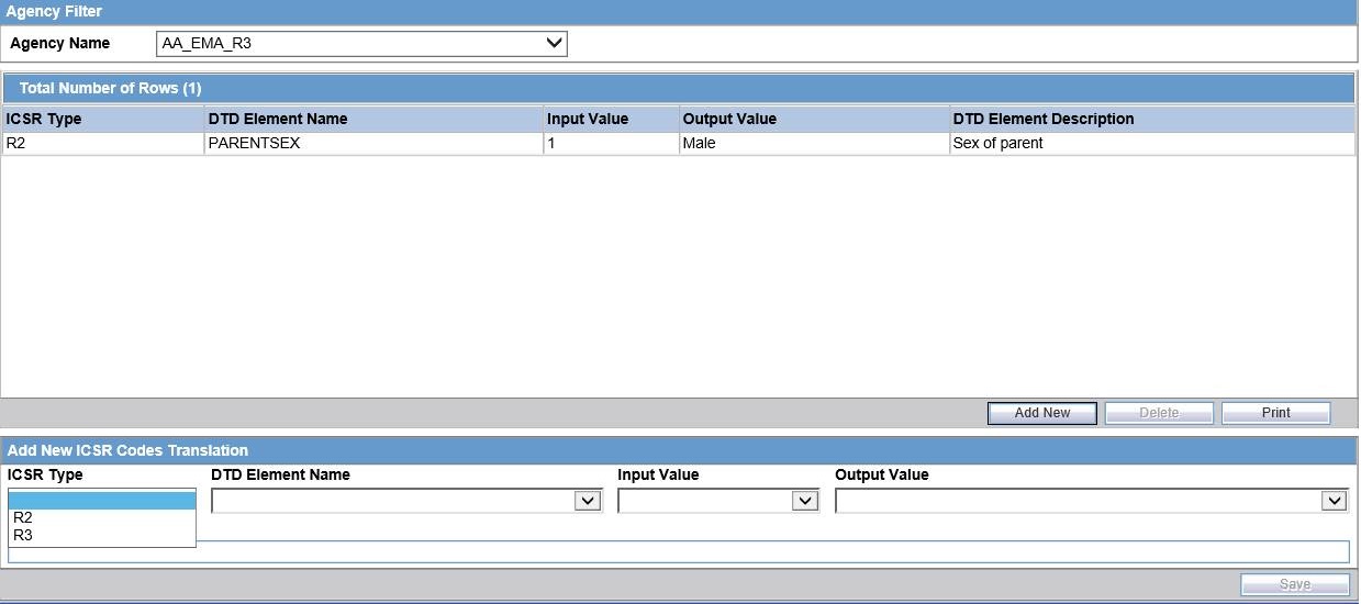
The Update and Update All buttons are never enabled when the profile selected from the Destination Profile is of the type template.3.5 ICSR Codes Translation
ICSR Codes Translation enables you to configure rules to translate the ICSR codes and values in the incoming ICSR reports, which come from different trading partners to preferred values in the AE system during case creation.
Go to Argus Console -> System Configuration -> Interchange Mapping -> ICSR Translation Codes to open the ICSR Code Translation screen.
Note:
Argus Console -> Interchange Mapping -> ICSR Code Translation has been enhanced to list all (R3) elements in addition to the existing elements in the DTD Element Name drop-down list as specified in Codelist Translation column of the Import Mapping xls. The values in this drop-down list are filtered based on what is selected in the newly added ICSR Type drop-down list, that is, if (R2) is selected, then all (R2) elements are listed and if (R3) is selected, all (R3) elements are listed.3.5.1 Configure ICSR Codes Translation
Use the following procedure to configure ICSR Codes Translation.
-
Select the Agency Name from the drop-down list box to display the Elements and their descriptions.
-
Click on the respective field to edit the Element Name, Input Value, Output Value, and Element Description.
-
Click Save to save your changes.
3.5.2 ICSR Codes Translation Fields
The following table lists and describes the fields on the ICSR Codes Translation screen.
| Item | Description |
|---|---|
| Agency Name | Enables the user to select an agency name from the drop-down list box. This drop-down lists the agencies configured with the (R3) profile (that supports the import of ICSRs) under the EDI tab (applicable for PMDA (R3) and EMA (R3) along with the (R2) agencies. |
| # | Displays the serial number. |
| ICSR Type | Enables the user to configure the translation code at the ICSR message type level. It lists two values (R2) (default) and (R3), and is enabled by default when the user creates any new entry to translation configuration. |
| Element Name | Displays the element name. |
| Input Value | Displays the type of input value. |
| Output Value | Displays the type of output value. |
3.6 View the Audit Log
The Audit Log stores changes made to the system from the application. You can also view and filter individual changes.
Use the following procedure to view the Audit Log:
-
On the Argus Interchange Mapping menu, click View Audit Log.
-
When the system opens the Audit Log dialog box, enter the appropriate data in each field and click Search.

Note:
For more information on Audit Log Dialog box fields, see Audit Log Dialog Box Fields. -
When the system displays the search results, double-click a row to view detailed information about the changes made in the Audit Log Detail dialog box.
-
Select an item in the list at the bottom of the Audit Log Details dialog to view details of the old and new values of the selected item.
3.6.1 Audit Log Dialog Box Fields
The following table lists and describes the fields on the Audit Log dialog box.
| Item | Description |
|---|---|
| From | Enter the search start date. |
| To | Enter the search end date. |
| Range | Select a pre-configured date range for the search.
Note: When the Argus Interchange Audit log is invoked, it shows the default range of the last 7 days. |
| User Name | Select a user from the list of users. |
| Prints the current view. | |
| Search | Performs the search. |
3.7 ICSR Extensions
For more details, from the Argus Safety OHC">>Argus Safety OHC page, download the Technical Reference Manuals, and refer to the >Oracle Argus Interchange ICSR Extensibility Guide.