| Oracle® Java ME Embedded Getting Started Guide for the Windows 32 Platform Release 3.2 E35132-01 |
|
 Previous |
 Next |
| Oracle® Java ME Embedded Getting Started Guide for the Windows 32 Platform Release 3.2 E35132-01 |
|
 Previous |
 Next |
The Windows emulation environment provides you with a platform for testing and running IMP-NG IMlet suites without having to install those IMlet suites onto an embedded device. This chapter describes running the emulation environment.
This chapter also shows you how to run the software on a Microsoft Windows system using the emulation environment that is provided in the reference binary. It assumes that you have downloaded the reference binary onto a Windows-based desktop platform.
The first step is to verify your current Java SE Platform. Tools that are provided with the software are based on the Java Platform, Standard Edition (Java SE), Version 7, Update 5. To properly use these tools, you must have a compatible version of the Java Runtime Environment (JRE) installed on your computer and set as the default version.
To check if you have an appropriate version of the Java SE platform installed on your computer, use the java -version command, as shown here:
C:\>java -version
java version "1.7.0_03"
Java(TM) SE Runtime Environment (build 1.7.0_03-b05)
Java HotSpot(TM) Client VM (build 22.1-b02, mixed mode, sharing)
The version number shown in the output should be version 1.7.0_01 or higher.
If you need to install a compatible version of the Java SE platform, you can download it from the following address:
You can find the Java ME Embedded emulator within the bin directory of the Java ME SDK 3.2 installation.
For example, if the Java ME SDK 3.2 is installed in C:\Java_ME_platform_SDK_3.2, then the emulator would be located at: C:\Java_ME_platform_SDK_3.2\bin\emulator.exe
To start the emulator and open an emulator window, enter the following command from the bin directory:
EmulatorDir>emulator.exe -Xdevice:IMPNGPhone1 -Xdescriptor:location_of_jad_file
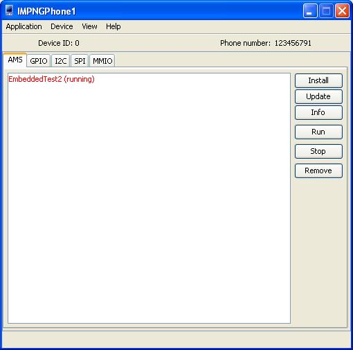
The emulator's main screen appears as shown in Figure 1-1. The first tab in the emulator, AMS (Application Management System), displays which Java ME Embedded applications are installed, including those that are currently running or stopped. You can use the buttons on the right side to install or update additional applications, obtain information about the currently selected application, start or stop an application, or remove (uninstall) an application from the AMS.
The current status of each Java ME Embedded application is shown in the panel on the left side as shown in Figure 1-1.
Figure 1-1 The Java ME Embedded Emulator Screen on Windows
|
Note: You can run the |
If no -Xdevice option is specified, the IMPNGPhone1 device is started by default.
For information on other emulator commands and options, see "Other Common Emulator Commands".
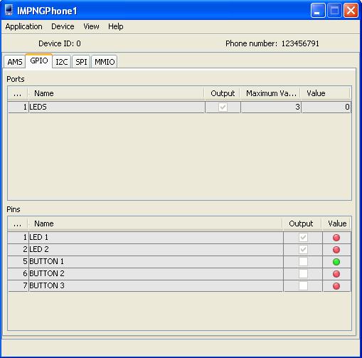
The GPIO tab lists the emulator's current General Purpose I/O (GPIO) pins and ports, and their directional states (input or output). For GPIO pins, the current value is shown as a color-coded circle on the right side: high is colored green, while low is red. For GPIO ports, the maximum and current value is shown. If a GPIO port or pin is named, it is shown in this tab as well.
The GPIO tab is shown in Figure 1-2:
Figure 1-2 Emulator General Purpose I/O (GPIO) Tab
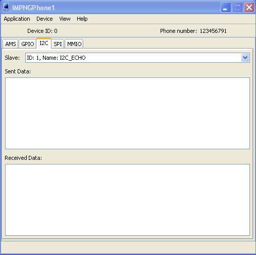
The Inter-Integrated Circuit (I2C) tab emulates a simple peripheral slave device that echoes back any data that is sent to it. Both the sent and received data are shown in their appropriate window panes, as shown in Figure 1-3:
Figure 1-3 Inter-Integrated Circuit (I2C) Tab
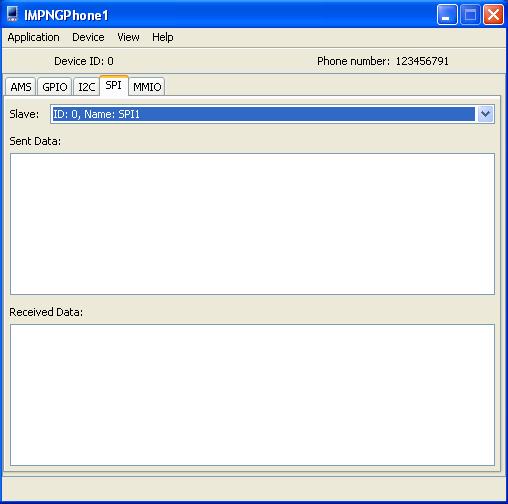
The Serial Peripheral Interface (SPI) tab is similar to the I2C tab. It emulates a simple peripheral slave device that echoes back any data that is sent to it. Both the sent and received data are shown in their appropriate tabs, as shown inFigure 1-4:
Figure 1-4 Serial Peripheral Interface Tab
Finally, the MMIO tab emulates the Memory-Mapped I/O (MMIO) interface bus. The MMIO interface creates four separate devices that can be used for testing: TEST_DEVICE, WDOG_LOG, RTC, and BIG_ENDIAN_DEVICE. Each type of device displays its appropriate block configuration in an information table, as shown in Figure 1-5:
Selecting the Device menu allows the user to configure several items on the device. The Access Points tab allows the user to configure the settings returned by various methods of the Access Point API, including Wi-Fi and carrier networks.
The File Connection tab allows the user to mount external file systems. In addition, the Location tab allows the device to specify the simulated location, orientation, and speed of the device. The SIM 0 and SIM 1 tabs allow the user to specify the hardware values of one of two subscriber identity module (SIM) cards that are typically installed in mobile devices.
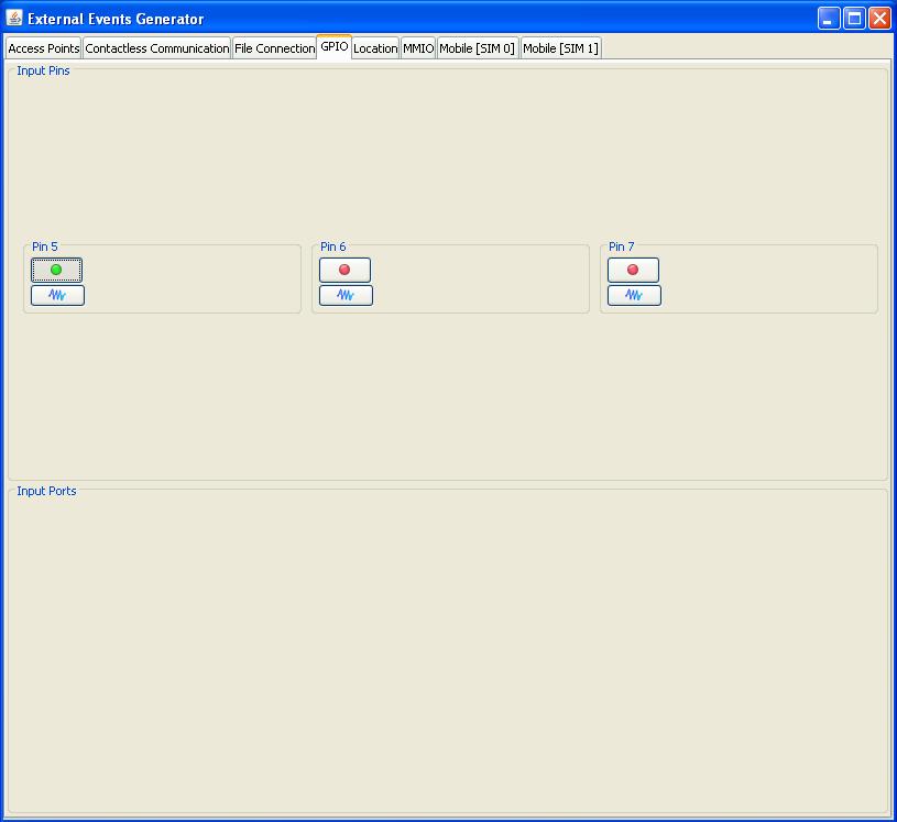
To generate input events for General Purpose I/O (GPIO), select the GPIO menu item under the Device menu. This action raises the External Events Generator window. Here, you can toggle the value of each of the pins from high to low and vice versa, and use a wave generator to simulate a more complex signal to the emulator. The GPIO External Events Generator is shown in Figure 1-6:
Figure 1-6 GPIO Tab of the External Events Generator
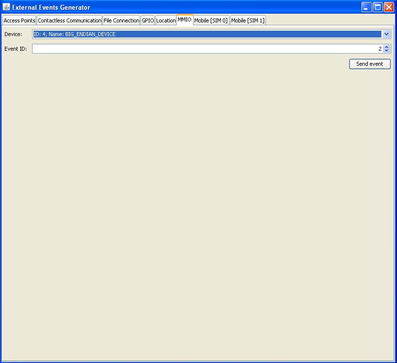
In addition, selecting the MMIO tab of the External Events Generator allows the user to simulate sending input event IDs from one of the four different peripheral device types. This tab is shown in Figure 1-7:
Figure 1-7 MMIO Tab of the External Events Generator
The Device Manager is started the first time the emulator is started. Its purpose is to manage multiple devices and device storage, so that multiple devices can be emulated without overwriting or colliding with each other.
When the Device Manager is started, it stays running as an icon in your system tray. To interact with the Device Manager, right-click the icon to display the Device Manager menu.
The Oracle Java ME Embedded platform comes with a number of sample applications. This section describes how to use demos created specifically for the Oracle Java ME Embedded platform. Because IMP-NG is headless, the only user interface is to observe application status in the emulator's external events generator, or in the Output window (or the console if you execute the demo from the command line).
With the exception of I2CDemo, the sample projects provided with the Oracle Java ME Embedded release can be run on the emulator or on a real device.
Note that in the _policy.txt file of the distribution (typically located in the runtimes/impng/lib directory), the developer may need to add the following entries to avoid security exceptions when running the samples:
To both the domains:
domain: untrusted, unsecured
domain: unidentified_third_party, unsecured
Add the following entry:
allow: device_access
This demo can be run on an IMP-NG emulator using the external events generator:
Click the GPIO tab. This view approximates the device actions.
Choose Device > GPIO to open the external events generator, and click the GPIO tab. A single click on a button turns on LEDs indicating the button pushed and the pin affected. This information is also written to the Output window.
Beneath each pin you can click the blue wave button to open the wave generator. The wave generator simulates the frequency and duration of the signal to the LED.
Press Pin 5 (button 1) to turn on LED 1, press again to turn off LED 1.
Press Pin 6 (button 2) to turn on LED 2, press again to turn off LED 2.
Press Pin 7 (button 3) and check whether PORT 1's output value is 3. Press PIN 7 and check whether PORT 1's output value is 0.
This demo is designed to work with the IMP-NG runtime for Windows 32. It has no user interaction.
Launch the I2C demo.
In the emulator, click the I2C tab.
The demo acquires a slave named I2C_Echo, writes data to the slave, and retrieves it. The demo is successful if the Sent Data and Received Data matches.
This demo can be configured as a server or as a client by editing the application descriptor. You launch two instances of this demo, the first one acts as a server and the second one acts as a client. The client instance attempts to connect to the server instance and if the connection is successful they exchange a message.
Create two instance projects of the NetworkDemoIMPNG sample project.
Right click on the first project and select Properties. In the Platform category choose the device IMPNGPhone1. In the Application Description category set the value of the property Oracle-Demo-Network-Mode to Server and click OK.
Launch the first project. It opens on the emulator IMPNGPhone1 and waits for a connection.
Right click on the second project and select Properties. In the Platform category choose the device IMPNGPhone2. In the Application Description category set the value of the property Oracle-Demo-Network-Mode to Client and click OK.
Launch the second project. It opens on the emulator IMPNGPhone2.
The client attempts to connect to the server. If successful, you see the following in the output tab of the first project (the server):
Connection accepted
Message received - Client messages
The output of the second project (the client) shows the following:
Connected to server localhost on port 5000
Message received - Server String
Follow these steps to run the demo on the IMP-NG emulator:
Create test files and directories inside the emulator's file system:
Documents and Settings\user\javame-sdk\version\work\IMPNGPhone1\appdb\filesystem\root1
Right click on the project and select Properties. In the Platform category choose the device IMPNGPhone1 and click OK.
Launch the project. It runs on IMPNGPhone1.
On the emulator menu, select Device > File Connection to see a list of mounted file systems.
Open a terminal emulator and create a raw connection to localhost on port 5001.
A command line opens where you can browse the emulator's file system. You can use the following commands:
cd - change directory
ls - list information about the FILEs for the current directory)
new - create new file or directory
prop - show properties of a file
rm - remove the file
view -View a file's content
This section provides emulator commands.
|
Note: For a full list of Emulator commands, type: |
To show a list of installed IMlets, use the -Xjam:list subcommand:
EmulatorDir>emulator -Xjam:list
To see a list of all supported devices, use the -Xquery subcommand:
EmulatorDir>emulator -Xquery
To install a JAD over the air (OTA) and execute a IMlet, use the -Xjam:install subcommand:
EmulatorDir>emulator -Xjam:install=<JAD_file_URL>
For example:
EmulatorDir>emulator -Xjam:install=http://www.appstore.com/TestJAD.jad
To run an installed IMlet, use the -Xjam:run subcommand:
EmulatorDir>emulator -Xjam:run=[storage_name | storage_number]
Provide either the storage name or storage number for the IMlet to run. You can get the storage name and storage number from the list of IMlets shown by the -Xjam:list subcommand.
To remove an installed IMlet, use the -Xjam:remove subcommand:
EmulatorDir>emulator -Xjam:remove=[storage_name | storage_number | all]
Provide either the storage name or storage number for the IMlet to remove. To remove all IMlets, use all. You can get the storage name and storage number from the list of IMlets shown by the -Xjam:list subcommand.
To install a JAD file, execute the IMlet locally, and remove the IMlet when completed, use the -Xdescriptor subcommand:
EmulatorDir>emulator -Xdescriptor:<JAD_file_name>
To set an IMlet's security domain, use the -Xdomain subcommand:
EmulatorDir>emulator -Xdomain:<domain_name>
To run in autotest mode, use the -Xautotest subcommand:
EmulatorDir>emulator -Xautotest:<JAD_file_URL>
For example:
EmulatorDir>emulator -Xautotest:http://127.0.0.1:8080/getNextApp.jad