| Oracle® Java ME Embedded Getting Started Guide for the Reference Platform (Keil) Release 3.3.1 E38140-02 |
|
 Previous |
 Next |
| Oracle® Java ME Embedded Getting Started Guide for the Reference Platform (Keil) Release 3.3.1 E38140-02 |
|
 Previous |
 Next |
This appendix describes the proper ID and names for the various peripheral ports and buses for the Keil MCBSTM32F200 embedded board, which are accessible using the Device Access APIs. Note that any IMlet that accesses the Device Access APIs must be digitally signed using a trusted certificate authority. An IMlet that is not signed will encounter an authentication error when attempting to access the Device Access APIs.
The Keil Reference Manual for the MCBSRM32F200 board provides additional technical information about the peripherals accessible via the Device Access APIs.
The following ADC channels are pre-configured.
| DAAPI Peripheral ID | DAAPI Peripheral Name | Mapped To | Configuration |
|---|---|---|---|
|
110 |
ADC1 |
On-board Potentiometer connected to PF9 |
converterNumber = 1 channelNumber = 7 resolution = 12 samplingInterval = 14857 samplingTime = 15000 (ignored) |
The following additional ADC channels are available ad-hoc.
| Mapped To | Converter(s) | Channel | Notes |
|---|---|---|---|
|
PF6 |
2 |
4 |
Not connected |
|
PF7 |
2 |
5 |
Not connected |
|
PF8 |
2 |
6 |
Not connected |
|
PF10 |
2 |
8 |
Not connected |
|
PA3 |
0-2 |
3 |
USBHS (USBHS_EN J2) |
|
PA5 |
0-1 |
5 |
Microphone (M_DATA J5), DAC2 |
|
PA6 |
0-1 |
6 |
Camera (CAM_EN J17) |
|
PB0 |
0-1 |
8 |
USBHS (USBHS_EN J2) |
|
PB1 |
0-1 |
9 |
USBHS (USBHS_EN J2) |
|
PC0 |
0-2 |
11 |
USBHS (USBHS_EN J2) |
|
PF9 |
2 |
7 |
Potentiometer |
Additional notes:
There are 48 total channels. For more information on assigned external pins, see the manufacturer board schematics.
For the converter number, acceptable values range from 0 to 2, which map to ADC1 to ADC3 on the device. For the channel number, acceptable values range from 0 to 15. Note that only one channel may be opened on each converter at a time. Consequently, only three channels may be in operation at any one time.
The internal sampling values range from [14857, 46857]. However, the sampling time is ignored.
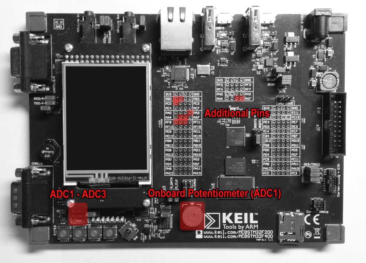
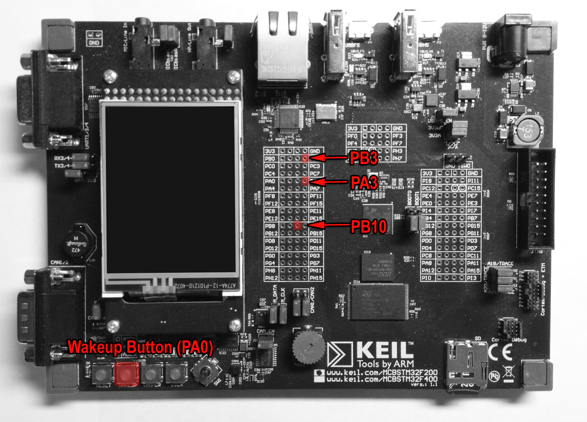
There are four pulse counters on the board. Each has a GPIO pin source: PA0, PB3, PB10, and PA3. Note that each source has only one counter, so the "number" property is not used for the Keil board.
The following pulse counters are pre-configured:
| DAAPI Peripheral ID | DAAPI Peripheral Name | Mapped To | Configuration |
|---|---|---|---|
|
201 |
COUNTER_PA0 |
“WAKEUP” button connected to PA0 |
counterNumber - not supported / ignored type = PulseCounterConfig.TYPE_FALLING_EDGE_ONLY portNumber = 0 pinNumber = 0 |
|
202 |
COUNTER_PB3 |
PB3 |
counterNumber - not supported / ignored type = PulseCounterConfig.TYPE_FALLING_EDGE_ONLY portNumber = 1 pinNumber = 3 |
|
203 |
COUNTER_PB10 |
PB10 |
counterNumber - not supported / ignored type = PulseCounterConfig.TYPE_FALLING_EDGE_ONLY portNumber = 1 pinNumber = 10 |
|
204 |
COUNTER_PA3 |
PA3 |
counterNumber - not supported / ignored type = PulseCounterConfig.TYPE_FALLING_EDGE_ONLY portNumber = 0 pinNumber = 3 |
There are no pulse counters available ad-hoc.
The following DAC devices are pre-configured:
| DAAPI Peripheral ID | DAAPI Peripheral Name | Mapped To | Configuration |
|---|---|---|---|
|
120 |
DAC1 |
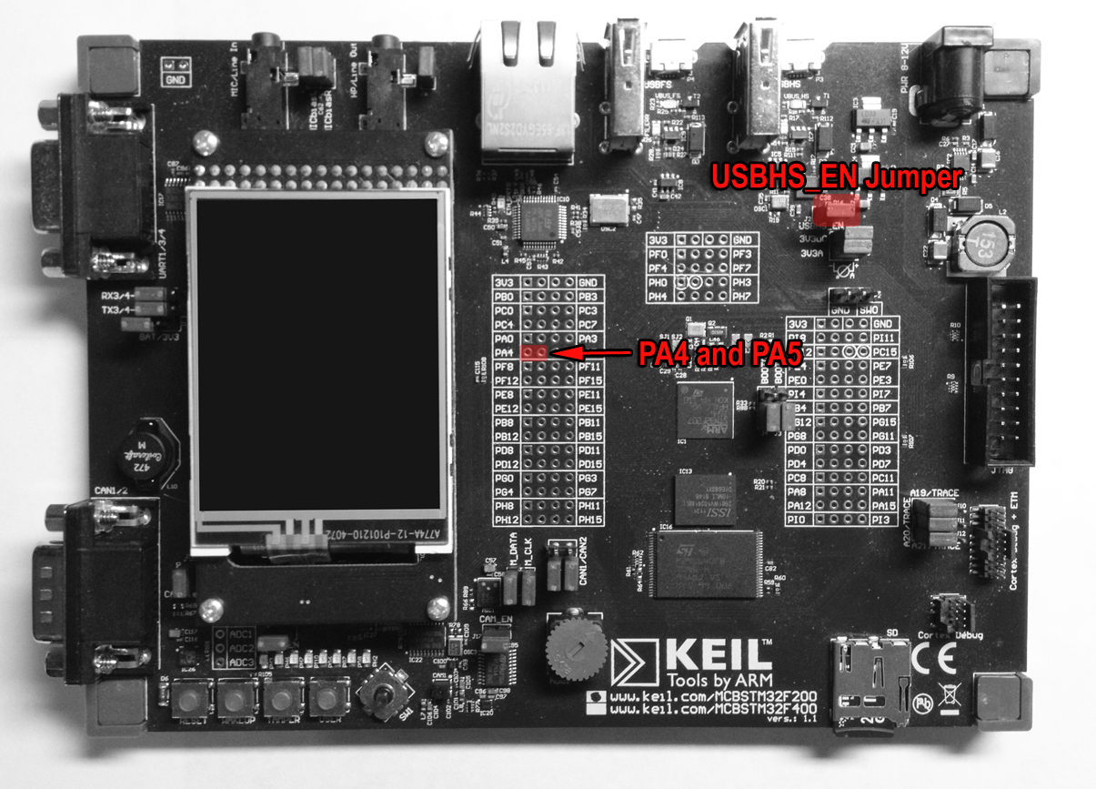
PA4, connected to Analog input 'AINT1A' of CODEC IC11 |
converterNumber = 0 channelNumber = 0 resolution = 12 samplingInterval = 1000 |
|
121 |
DAC2 |
PA5, connected to 'CLK' input of HS USB OTG transceiver IC6. To use DAC2 the IC should be disabled by disconnecting J2 'USBHS_EN' jumper |
converterNumber = 0 channelNumber = 1 resolution = 12 samplingInterval = 1000 |
There are no DAC channels available ad-hoc.
The following GPIO pins are pre-configured:
| DAAPI Peripheral ID | DAAPI Peripheral Name | Mapped To | Configuration |
|---|---|---|---|
|
1 |
LED 1 |
LED PH3 |
portNumber = 7 pinNumber = 3 direction = GPIOPinConfig.DIR_OUTPUT_ONLY mode = GPIOPinConfig.MODE_OUTPUT_PUSH_PULL trigger = GPIOPinConfig.TRIGGER_NONE initValue = false |
|
2 |
LED 2 |
LED PH6 |
portNumber = 7 pinNumber = 6 direction = GPIOPinConfig.DIR_OUTPUT_ONLY mode = GPIOPinConfig.MODE_OUTPUT_PUSH_PULL trigger = GPIOPinConfig.TRIGGER_NONE initValue = false |
|
3 |
LED 3 |
LED PH7 |
portNumber = 7 pinNumber = 7 direction = GPIOPinConfig.DIR_OUTPUT_ONLY mode = GPIOPinConfig.MODE_OUTPUT_PUSH_PULL trigger = GPIOPinConfig.TRIGGER_NONE initValue = false |
|
4 |
LED 4 |
LED PI10 |
portNumber = 8 pinNumber = 10 direction = GPIOPinConfig.DIR_OUTPUT_ONLY mode = GPIOPinConfig.MODE_OUTPUT_PUSH_PULL trigger = GPIOPinConfig.TRIGGER_NONE initValue = false |
|
5 |
WAKEUP_BUTTON or BUTTON 1 |
“WAKEUP” button |
portNumber = 0 pinNumber = 0 direction = GPIOPinConfig.DIR_INPUT_ONLY mode = GPIOPinConfig.MODE_INPUT_PULL_DOWN trigger = GPIOPinConfig.TRIGGER_RISING_EDGE initValue - ignored |
|
6 |
TAMPER_BUTTON or BUTTON 2 |
“TAMPER” button |
portNumber = 2 pinNumber = 13 direction = GPIOPinConfig.DIR_INPUT_ONLY mode = GPIOPinConfig.MODE_INPUT_PULL_UP trigger = GPIOPinConfig.TRIGGER_FALLING_EDGE initValue - ignored |
|
7 |
USER_BUTTON or BUTTON 3 |
“USER” button |
portNumber = 6 pinNumber = 15 direction = GPIOPinConfig.DIR_INPUT_ONLY mode = GPIOPinConfig.MODE_INPUT_PULL_UP trigger = GPIOPinConfig.TRIGGER_FALLING_EDGE initValue - ignored |
|
WARNING: The information in this appendix is presented in addition to the board schematics provided by the manufacturer. Be sure to familiarize yourself with the manufacturer's documentation for all of the GPIO pins. Failure to do so can result in damaged peripherals or even a damaged embedded board. |
The following GPIO pins are available ad-hoc. Note that some GPIO pins are used at the system level, so opening those pins may affect board behavior.
Accepted port numbers are PA=0, PB=1, PC=2, PD=3, PE=4, PF=5, PG=6, PH=7, PI=8.
Accepted pins number are from 0 to 15.
Depending on the board, PB0 and PB1 may be unused.
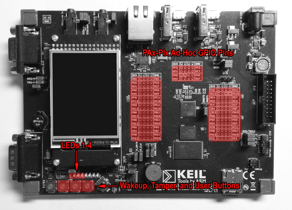
The following GPIO ports are pre-configured:
| DAAPI Peripheral ID | DAAPI Peripheral Name | Mapped To | Configuration |
|---|---|---|---|
|
8 |
LEDS |
PH3, PH6, PH7, PI10 |
direction = GPIOPortonfig.DIR_OUTPUT_ONLY initValue = 0 mode of pins = GPIOPinConfig.MODE_OUTPUT_PUSH_PULL |
The following GPIO ports are available ad-hoc:
All combinations of available pins
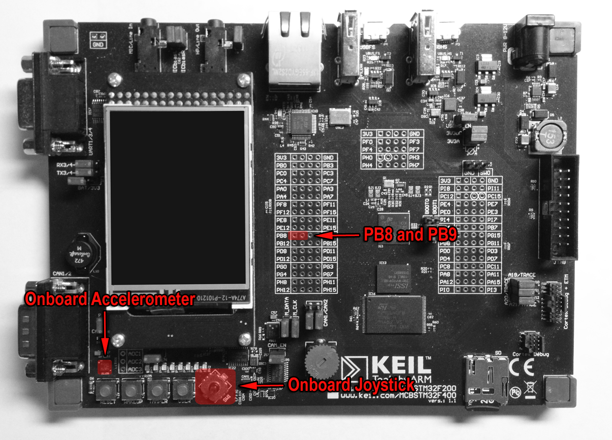
The following I2C devices are pre-configured:
| DAAPI Peripheral ID | DAAPI Peripheral Name | Mapped To | Configuration |
|---|---|---|---|
|
50 |
I2C_JOYSTICK |
On-board Joystick connected via I2C bus |
busNumber = 0 address = 68 clockFrequency = 100000 |
|
51 |
LIS3DH |
LIS3DH MEMS motion sensor(On-board 3-axis accelerometer connected via I2C bus) |
busNumber = 0 address = 24 clockFrequency = 100000 |
The following I2C devices are available ad-hoc using connectors PB8 and PB9:
Any address on bus 0
The following MMIO peripherals are available:
| DAAPI Peripheral ID | DAAPI Peripheral Name | Mapped To | Configuration |
|---|---|---|---|
|
10 |
TEST_DEVICE |
byteOrdering = Peripheral.LITTLE_ENDIAN |
|
|
1001 |
WDOGLOG |
byteOrdering = Peripheral.LITTLE_ENDIAN |
|
|
999 |
RTC |
byteOrdering = Peripheral.LITTLE_ENDIAN |
The MMIO raw memories are shown here:
| DAAPI Peripheral ID | Name | Address | Type and Size |
|---|---|---|---|
|
10 |
BYTE |
0x2001FE00 |
byte 1 |
|
10 |
SHORT |
0x2001FE04 |
short 2 |
|
10 |
INT |
0x2001FE08 |
int 4 |
|
10 |
BLOCK |
0x2001FE20 |
block 256 |
|
1001 |
WDOG_LOG |
0x607F0000 |
block 65536 |
|
999 |
WPR |
0x40002824 |
int 4 |
|
999 |
CR |
0x40002808 |
int 4 |
|
999 |
DR |
0x40002804 |
int 4 |
|
999 |
TR |
0x40002800 |
int 4 |
|
999 |
ISR |
0x4000280C |
int 4 |
Note that the addresses [0x2001FE00 - 20020000) are part of the external RAM reserved for MMIO, and any type will be allowed. In addition, the addresses [0x40000000 - 0x50060C00) and [0xA0000000 - 0xA0001000) are peripheral IO registers. Be sure to check the manufacturer's documentation for actual sizes, type and valid values. With each of the addresses above, the final address is non-inclusive.
There are no devices with event support.
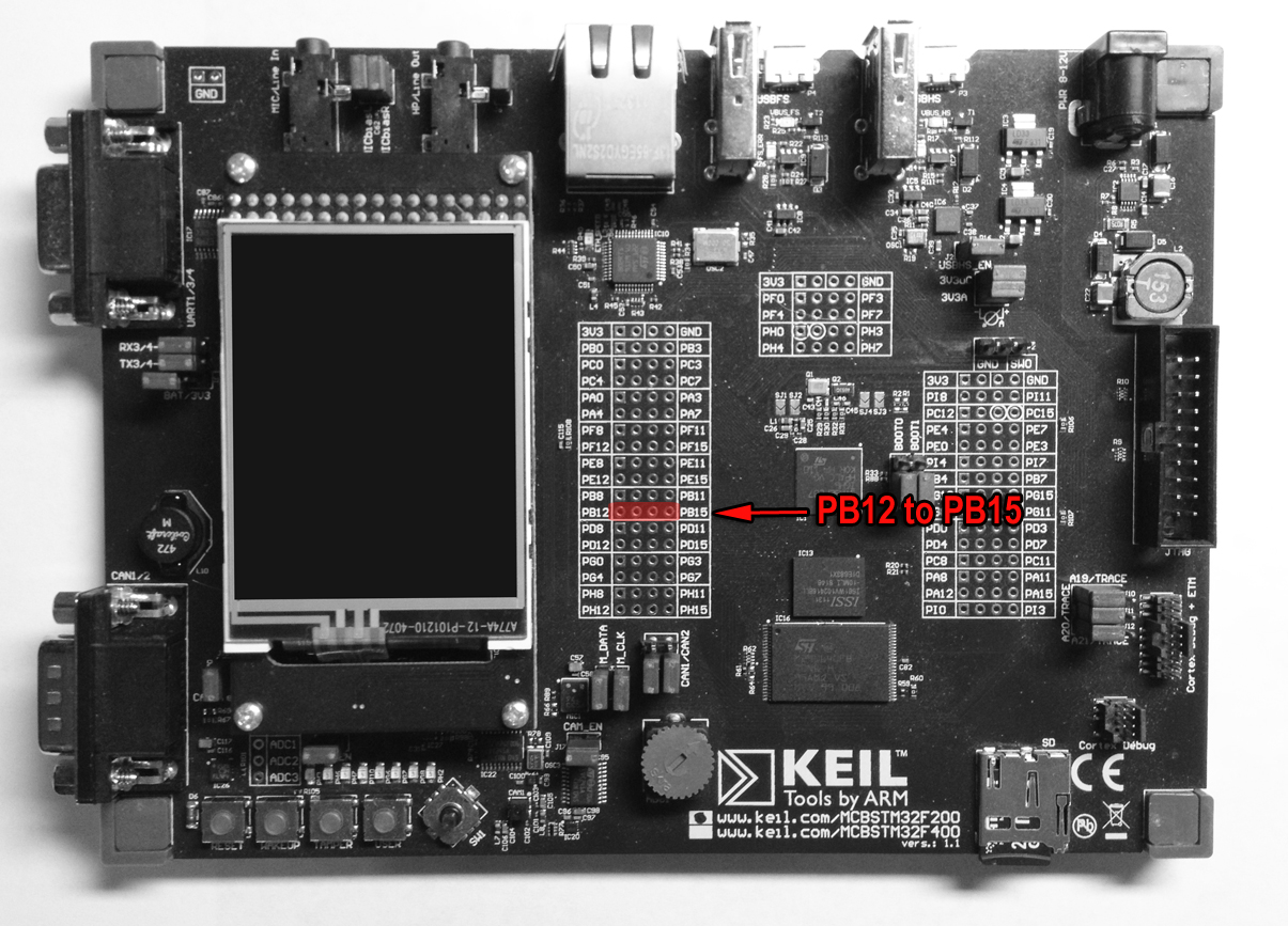
The following SPI devices are pre-configured:
| DAAPI Peripheral ID | DAAPI Peripheral Name | Mapped To | Configuration |
|---|---|---|---|
|
12 |
SPI2_Slave |
MOSI on PB15 MISO on PB14 SCK on PB13 CS on PB12 |
busNumber = 1 address = 0 clockFrequency = 2000000 clockMode = 1 wordLength = 8 bitOrdering = 1 Configuration is tested with external SPI Digital thermometer (DS1722, Dallas Semiconductor) |
The following SPI devices are available ad-hoc:
SPI bus numbers: SPI1 = 0; SPI2 = 1; SPI3 = 2
Clock frequency: 2MHz = 2000000; 25MHz = 25000000; 50MHz = 50000000; 100MHz = 100000000
Clock polarity and phase: 0 = CPOL_Low | CPHA_1Edge; 1 = CPOL_Low | CPHA_2Edge; 2 = CPOL_High | CPHA_1Edge; 3 = CPOL_High | CPHA_2Edge
Bit ordering for data transfers: MSB = 1; LSB = 0
The following UART devices are pre-configured:
| DAAPI Peripheral ID | DAAPI Peripheral Name | Mapped To | Configuration |
|---|---|---|---|
|
14 |
UART |
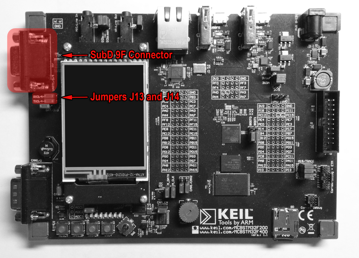
Connected to SubD 9F connector if jumpers J13 and J14 are set to TX3/4 and RX3/4 (for 1.1 boards version only) |
uartNumber = 0 baudRate = 19200 dataBits = UARTConfig.DATABITS_8 or UARTConfig.DATABITS_9 parity = UARTConfig.PARITY_NONE or UARTConfig.PARITY_EVEN or UARTConfig.PARITY_ODD stopBits = UARTConfig.STOPBITS_1 or UARTConfig.STOPBITS_2 flowcontrol = UARTConfig.FLOWCONTROL_NONE |
The are no UART devices available ad-hoc.
The deviceaccess.uart.prefix property in the jwc_prop.ini file may contain a prefix for easy conversion of the UARTConfig.portNumber value to a platform-specific port name. For example, the property may be set to "COM" in a Windows environement, or "UART" in a Keil environment such that appending on a port number will correctly map to the port name.
