| Oracle® Java ME Embedded Getting Started Guide for the Windows Platform Release 3.4 E35132-03 |
|
 Previous |
 Next |
| Oracle® Java ME Embedded Getting Started Guide for the Windows Platform Release 3.4 E35132-03 |
|
 Previous |
 Next |
The Oracle Java ME SDK emulation environment provides you with a platform for testing and running IMP-NG IMlet suites without having to install those IMlet suites onto an embedded device. This chapter describes running the emulation environment.
This chapter continues from For the Eclipse IDE, some small differences may appear. On the whole, the descriptions of the emulator for the NetBeans IDE map closely to the emulator for the Eclipse IDE.
The Oracle Java ME SDK emulator can also be started from the Windows command line and can be run without starting either NetBeans or Eclipse. For more information on using the emulator from the command line, see Appendix B, "Using the Command Line Emulator."
The Oracle Java ME SDK emulator provides several ways to interact with an emulated device (for example, the IMPNGDevice1), as shown in Figure 3-1.
The Application menu (and associated icons) allow you to install and run IMlet suites.
The Tools menu allows you to manage a Landmark Store or file system.
The External Events Generator icon (and Tools menu option) allows you to configure pins, ports, interfaces, and other customizable parts.
The View menu allows you to display log information and other output in a console window.
The Help menu allows you to display context-sensitive help to get more information about the emulator screen and functions.
Figure 3-1 The Oracle Java ME SDK Emulator Toolbar and Menu Items
When the Oracle Java ME SDK emulator starts, it appears with the Application Management System (AMS) tab selected as the default, as shown in Figure 3-2.
Figure 3-2 The Oracle Java ME SDK Emulator (AMS Tab) Default Screen
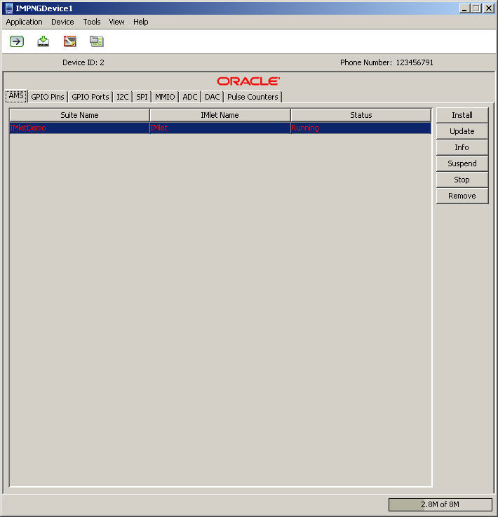
The first tab in the emulator, the AMS tab, displays which Oracle Java ME SDK applications are installed, including those that are currently running or stopped.
You can use the buttons in the AMS tab, as shown in Figure 3-3, to do the following:
Install or update additional applications
Obtain information about a currently-selected application
Start, Stop, or Suspend an application
Remove (uninstall) an application from the AMS
The GPIO tab lists the emulator's current General Purpose I/O (GPIO) pins and their directional state (output). For GPIO pins, the current value is shown as low or high. The GPIO Pins tab is shown in Figure 3-4:
For GPIO ports, the port ID and port Name is shown, along with the port's Maximum Value and current Value., as shown in Figure 3-5.
The Inter-Integrated Circuit (I2C) tab emulates a simple peripheral slave device that echoes back any data that is sent to it. Both the sent and received data are shown in their appropriate window panes, as shown in Figure 3-6:
The Serial Peripheral Interface (SPI) tab is similar to the I2C tab. It emulates a simple peripheral slave device that echoes back any data that is sent to it. Both the sent and received data are shown in their appropriate tabs, as shown in Figure 3-7:
The MMIO tab emulates the Memory-Mapped I/O (MMIO) interface bus. The MMIO interface creates four separate devices that can be used for testing: TEST_DEVICE, WDOGLOG, RTC, and BIG_ENDIAN_DEVICE. Each type of device displays its appropriate block configuration in an information table, as shown in Figure 3-8:
The Audio-to-Digital Converter (ADC) tab displays current Channel information, such as ID, Converter Number, Minimum and Maximum Values, and Sampling Intervals, as shown in Figure 3-9.
The Digital-to-Audio Converter (DAC) tab displays current Channel information, such as Minimum and Maximum Values, Sampling Interval, and Reference Voltage, as shown in Figure 3-10.
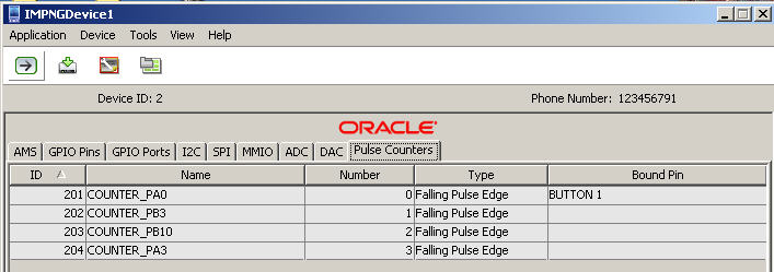
The Pulse Counters tab allows you to send pulse information to as many as four counters. as shown in Figure 3-11. There are four kinds of pulses:
Falling Pulse Edge - Can only be bound to input pins with the Falling Edge trigger.
Rising Pulse Edge - Can only be bound to input pins with the Rising Edge trigger.
Negative Pulse Edge - Can only be bound to input pins with the Both Edges trigger.
Positive Pulse Edge - Can only be bound to input pins with the Both Edges trigger.
Figure 3-11 The Emulator Pulse Counters Tab
The External Events Generator allows you to test the capabilities of your device by simulating events on that device. For example, you can send pulses to a pulse counter or define an access point for network connectivity.
The External Events Generator is started by clicking on the External Events Generator tab, as shown in Figure 3-1, or by selecting Tools --> External Events Generator.
When the External Events Generator is started the default tab is the Audio-to-Digital Converter tab, as shown in Figure 3-12.
Figure 3-12 The External Events Generator ADC Tab

The Audio-to-Digital Converter (ADC) tab allows you to test audio input, as shown in Figure 3-12, including Channel, DAC Input, and minimum and maximum values.
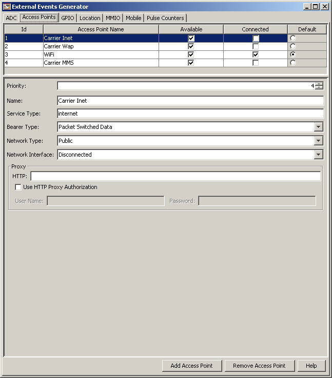
The Access Points tab allows the user to configure the settings returned by various methods of the Access Point API, including Wi-Fi and carrier networks, as shown in Figure 3-13.
Figure 3-13 The External Events Generator Access Points Tab
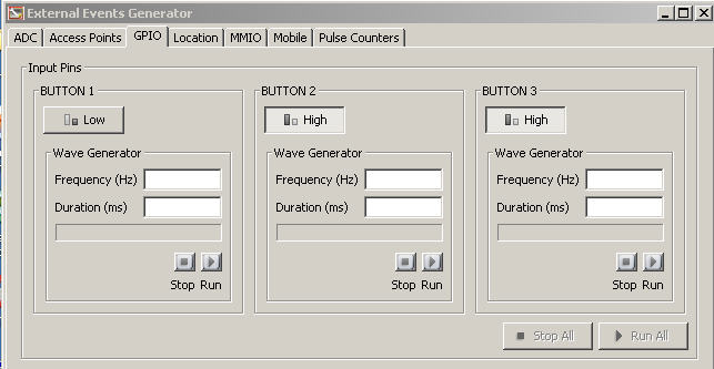
To generate input events for General Purpose I/O (GPIO), select the GPIO menu item under the Device menu. This action raises the External Events Generator window. Here, you can toggle the value of each of the pins from high to low and vice versa, and use a wave generator to simulate a more complex signal to the emulator. The GPIO External Events Generator is shown in Figure 3-14.
Figure 3-14 The External Events Generator GPIO Tab
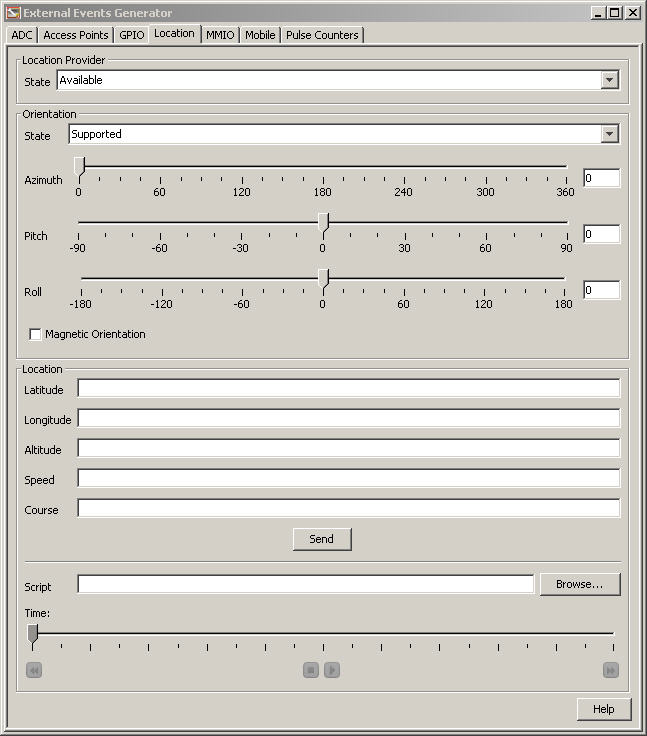
The Location tab allows the device to specify the simulated Location Provider, Orientation, and other settings, such as Latitude, Longitude, Altitude, Speed, and Course, as shown in Figure 3-15.
Figure 3-15 The External Events Generator Location Tab
The MMIO tab of the External Events Generator allows the user to simulate sending input event IDs to one of the four different peripheral device types. This tab is shown in Figure 3-16.
Figure 3-16 The External Events Generator MMIO Tab

|
Note: The External Events Generator Mobile tab is not used by Embedded Applications so it is not documented here. |
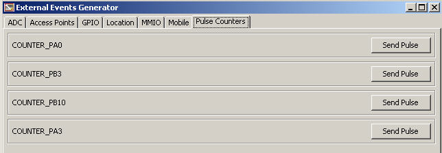
The Pulse Counter tab allows you to send a a sequence of pulses to as many as four pulse counters, as shown in Figure 3-17.
Figure 3-17 The External Events Generator Pulse Counters Tab
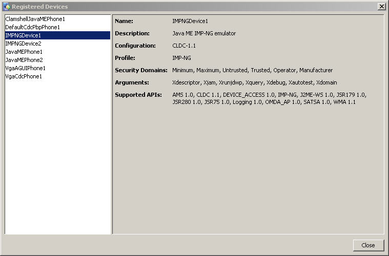
The Device Manager is started the first time the emulator is started. Its purpose is to manage multiple devices and device storage, so that multiple devices can be emulated without overwriting or colliding with each other. The list of registered devices is shown in Figure 3-18.
|
Note: The Oracle Java ME SDK supports many device types, but only two are used by Embedded Applications: IMPNGDevice1 and IMPNGDevice2. |
Figure 3-18 A List of Registered Devices in the Device Manager
When the Device Manager is started, it stays running as an icon in your system tray. To interact with the Device Manager, right-click the icon to display the Device Manager menu.
The Device Manager also allows you to add the IP address of one or more additional devices using the Device Address Manager, as shown in Figure 3-19.