| Oracle® Java ME Embedded Getting Started Guide for the Windows Platform Release 8 EA 2 for NetBeans on Windows E48511-01 |
|
 Previous |
 Next |
| Oracle® Java ME Embedded Getting Started Guide for the Windows Platform Release 8 EA 2 for NetBeans on Windows E48511-01 |
|
 Previous |
 Next |
Beta Draft: 2014-02-15
This chapter describes the Oracle Java ME SDK 8 EA 2 components that allow you to work effectively with devices, including making device connections, creating, configuring, and customizing devices, and detecting external embedded devices.
The Oracle Java ME SDK 8 EA 2 provides three components for working with emulated and external devices in the NetBeans 8.0 Beta IDE:
Device Selector
Device Connections Manager
Custom Device Editor
The Device Connections Manager is started automatically when Oracle Java ME SDK 8 EA 2 is installed. However, its primary usefulness is for external embedded hardware is attached to the Windows 7 PC running
The Device Manager icon is put on your desktop when you first install Oracle Java ME SDK 8 EA 2, as shown in Figure 5-1. It's located in your Windows 7 system tray and can be run without starting the NetBeans 8.0 Beta.
Figure 5-1 The Device Connections Manager Icon
The Device Manager is an Oracle Java ME SDK 8 EA 2 service used to manage both emulators and external devices. The Device Manager automatically detects available devices (including any connected hardware devices) and lists those devices in the Device Selector window.
To use the Device Manager:
If not already running, the Device Manager can be started in two ways:
From NetBeans 8.0 Beta, select Tools > Java ME > Active Device Manager > Oracle Java(TM) ME SDK 8.0 EA
From the Windows command line. Type:
C:\>Java_ME_platform_SDK_8.0_EA\bin\device-manager.exe
When the Device Manager is in the Windows system tray, right-click the icon. This displays the Device Connections Manager menu, as shown in Figure 5-2.
Figure 5-2 The Device Connections Manager Menu

Select Manage Device Connections to display the Device Connections Manager screen, as shown in Figure 5-3.
Figure 5-3 The Device Connections Manager Screen
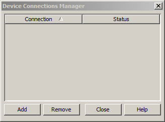
To add a new device connection, click Add. This displays the Add Device Connection box, as shown in Figure 5-4.
Figure 5-4 The Add Device Connection Form
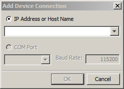
Enter an IP Address or Host Name (for example, localhost). Click OK.
If an embedded hardware device is attached, you can select a COM port for the hardware connection in the Select COM Port field.
If you have an address you no longer want to detect, select the address and click Remove. The device is no longer displayed in the Device Connections Manager.
To see a list of registered devices and their configuration information, right-click the Device Manager icon in the system tray and select Registered Devices, as shown in Figure 5-5.
The Device Selector lists the devices currently available in NetBeans 8.0 Beta, grouped by platform, as shown in Figure 5-6. If the Device Selector is not visible, click on the Device Selector tab, or select Tools > Java ME > Device Selector.
The list in the Device Selector matches the list displayed in the Registered Devices window, as shown in Figure 5-6.
|
Note: The |
The Device Selector can also be launched from the Windows command line. Enter the following:
C:\>Java_ME_platform_SDK_8.0_EA\bin\device-selector.exe
This displays the standalone Device Selector, as shown in Figure 5-7.
Figure 5-7 The Standalone Device Selector

Using the Device Selector, you can view properties information for a platform or a device.
The Properties window is, by default, located on the right side of the NetBeans 8.0 Beta user interface. If the Properties window is not visible, select Windows > IDE Tools >Properties
Instances of similar devices (for example, EmbeddedDevice1 and EmbeddedDevice2) have the same properties and capabilities, but unique names and phone numbers. This makes it easy for you to test communication between devices of the same type.
To view platform properties from the Device Selector, click on the platform name (for example, CLDC, Oracle Java ME SDK 8 EA 2). To view the platform properties in a separate window, right-click the platform node and select Properties. This displays the Platform Properties in a pop-up window, as shown in Figure 5-8.
In the Device Selector window, double-click on a device name (for example, EmbeddedDevice1). The Device Information tab opens in the Main window.
The Device Information window displays details about the device, such as the supported runtime, supported Java ME extensions, supported optional packages, and other capabilities, such as power management or cellular support, as shown in Figure 5-9.
In the Device Selector window, click a device name to display the properties for the device, as shown in Figure 5-10.
In the Device Selector window, right-click a device and select Properties. Any properties shown in gray font cannot be changed. You can adjust the device properties shown in black. Only MEEP options can be adjusted.
This section lists general properties that can be changed.
Remove IMlet Suite in execution mode. If this option is enabled, record stores and other resources created by the IMlet are removed when you exit the IMlet (assuming the IMlet was started in execution mode).
Phone Number. You can set the phone number to any appropriate sequence, considering country codes, area codes, and so forth. If you reset this value, the setting applies to future instances. The number is a base value for the selected device.
Heapsize. The heap is the memory allocated on a device to store your application objects. The Heapsize property is the maximum heap size for the emulator. You can select a new maximum size from the drop down menu.
Memory Limit Per Suite. This property allows you to define how much memory an IMlet suite is allocated upon launch. Unlimited means the IMlet can use as much memory as required to run.
JAM storage size in KB. The amount of space available for applications installed over the air.
Locale. Type in the locale as defined in the ME Embedded Profile specification at:
https://jcp.org/aboutJava/communityprocess/edr/jsr361/index.html
If enabled (checked), the Check boxes for Trace GC (garbage collection), Trace Class Loading, Trace Exceptions, and Trace Method Calls activate tracing for the selected device the next time the emulator is launched. The trace output is displayed at runtime in the user interface Output window.
|
Note: Trace Method Calls returns many messages, and emulator performance can be affected. |
Security and Trust Services (SATSA) provide the ability to define security settings. You can define the hostname of a Java Card emulator, and port numbers for slots 0 and 1.
These properties determine the selection of a location provider. Two providers are offered so that your application can be tested matching the location provider criteria.
If you select a property a short explanation is shown in the description area just below the Properties table. For more information on these values, see the Location API at:
Security properties for a device are set at the time the device is created, using the Client Security Model.
To edit security settings for a specific device in the Device Selector:
Select a device from the list of available devices, for example, EmbeddedDevice1, as shown in Figure 5-11.
Figure 5-11 The Device Selector Screen with a Selected Device
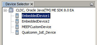
Right click on the selected device to display the device menu. Scroll down and select Edit Security Policy.
This displays the Security Policy screen, as shown in
EmbeddedDevice1 is a Signed device. The specific permissions that are granted to it are defined in the Permissions category. The certificates that verify its signing are listed in the Certificates category.
To edit the EmbeddedDevice1 security settings, do the following:
To add a Client, click Add in the Clients category. This displays the Add Client form, as shown in Figure 5-13. Enter the new Client name and click OK.
To add a Permission, click Add in the Permissions category. This displays the Add Permissions form, as shown in Figure 5-14. Select a permission from the drop down list in the Permission field, enter a Protected Resource Name, and click OK.
To edit a Permission, click Edit in the Permissions category. This displays the Edit Permissions form, as shown in Figure 5-15. Select a permission from the drop down list in the Permission field, and make other edits, for example, to the Actions Requested list, and click OK.
To add a Certificate, click Add in the Certificates category. This displays the Add Certificates form, as shown in Figure 5-16. Enter the certificate information and click OK.
Once you have finished making Security Policy changes, click OK. The next time you start the configured device, your changes will take effect.
Click Remove in any category to remove a Client, Permission, or Certificate, and click OK for it to take effect.
For more detailed information on the Security Client Model, see the Java ME Embedded Profile (MEEP) Specification, at:
https://jcp.org/aboutJava/communityprocess/edr/jsr361/index.html
With the Custom Device Editor you can create your own devices. The appearance of a custom device is generic, but the functionality can be tailored to your own specifications.
Follow these steps to create a custom device in NetBeans 8.0 Beta:
Select Tools > Java ME > Custom Device Editor
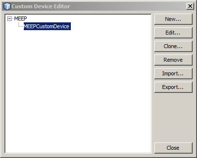
The Custom Device Editor is shown in Figure 5-17. The custom device tree displays platforms and custom devices, if any. For example, the ME Embedded Platform (MEEP).
To run a standalone Custom Device Editor, use the device-editor.exe command from the Windows command line. For example:
C:>Java_ME_platform_SDK_8.0_EA\bin\device-editor.exe
Select a platform and click the New... button. This displays the New Device dialog box, as shown in Figure 5-18.
Change the default Device Configuration or Device Profile to match the specifications for your new device.
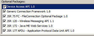
Select Optional Packages. Optional packages provide additional functionality to your device and can be individually selected to correspond to the configuration of your custom device, as shown in Figure 5-19.
Figure 5-19 New Custom Device Optional Packages
Define properties for the interfaces and protocols supported by your custom device, as shown in Figure 5-20. For more information on custom device protocols and property settings, see "Setting Custom Device Properties."
Click OK.
Your device is added to the custom device tree, as shown in Figure 5-21.
Figure 5-21 A Newly-Created Custom Device
Eventually, the newly-added device appears in the Device Selector. You can run projects from the IDE or from the command line for the custom device.
If you do not want a custom device to appear in the Device Selector, you must remove it from the custom device tree.
Once a newly created custom device is added to the Device Selector, the device definition is saved in:
<install_dir>\toolkit-lib\devices
When you create a new embedded device using the Custom Device Editor (Tools > Java ME > Custom Device Editor) you can use the default implementation or create your own custom implementation for the interfaces discussed in this section.
You can set device properties when you first create your custom device. Or, you can define device properties later, by selecting your custom device in the Custom Device Editor, as shown in Figure 5-21, and clicking Edit.
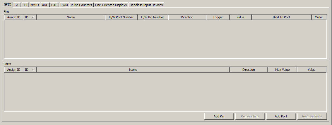
A GPIO port is a platform-defined grouping of GPIO pins that may be configured for output, input, or bidirectional. The custom device GPIO screen is shown in Figure 5-22.
Figure 5-22 The GPIO Custom Device Screen
To add a custom Pin:
Click Add Pin to add a row to the Pins table.
A new row is highlighted in the Pins table. To customize a field in the pin row, double-click in a cell and define the field for your custom device.
For additional pins, click Add Pin again. A second row is added, allowing you to define a second pin for your custom device. Add as many rows as required for the number of pins defined for your custom device.
To add a custom Port:
Click Add Port to add a row to the Ports table.
A new row is highlighted in the Ports table. To customize a field in the port row, double-click in a cell and define the field for your custom device.
For additional ports, click Add Port again. A second row is added, allowing you to define a second port for your custom device. Add as many rows as required for the number of ports defined for your custom device.
To remove a pin, highlight the row for the pin to be removed, and click Remove Pins. To remove a port, highlight the row for the port to be removed, and click Remove Ports.
When your custom device is fully configured, click OK to add it to the Custom Device Editor, as shown in Figure 5-21.
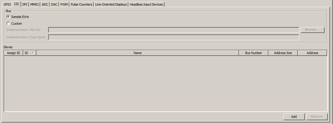
The Inter-Integrated Circuit (I2C) and Serial Peripheral Interface (SPI) are very similar. Each simulates a simple peripheral slave device that echoes back data sent to it. The I2C and SPI custom screens are also very similar, as shown in Figure 5-23.
Figure 5-23 The I2C or SPI Custom Device Screen
To create a custom I2C or SPI interface for your custom device:
Select Sample Echo to select the default bus. Or, select Custom to define your own bus implementation.
If you select Custom:
Supply your bus implementation JAR file and the name of the Java class that implements the bus.
For I2C, the bus is:
com.oracle.jme.toolkit.deviceaccess.i2c.I2CSlaveBus
For SPI, the bus is:
com.oracle.jme.toolkit.deviceaccess.spi.SPISlaveBus
To add Slaves, click Add and specify an ID and Name.
When your I2C or SPI device is defined, click OK. This adds the I2C or SPI implementation to your custom device.
To remove a row, select the row and click Remove.
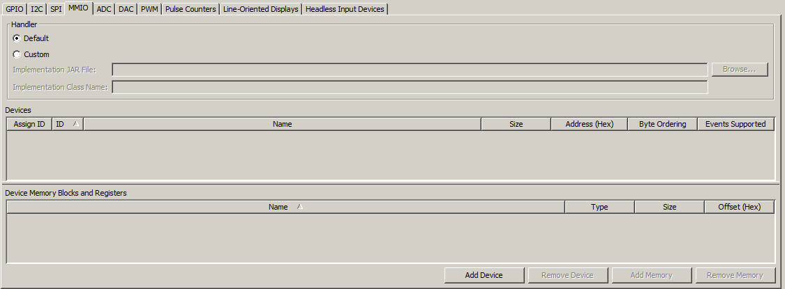
The MMIO tab emulates the Memory-Mapped I/O (MMIO) interface bus. It facilitates input/output between CPU memory and a peripheral device. To define a custom MMIO implementation use the MMIO custom device screen, as shown in Figure 5-24.
Figure 5-24 The MMIO Custom Device Screen
If you want to provide your own MMIO emulation, you must specify a custom handler.
To create a custom MMIO implementation:
Click Default to use the default handler JAR file. If you click Custom, you must specify a custom handler using the following fields:
Implementation JAR File. Supply a JAR file for your implementation.
Implementation Class Name. Supply the name of the Java class that implements com.oracle.jme.toolkit.deviceaccess.mmio.MMIOHandler.
The default handler JAR file is:
installdir\toolkit-lib\devices\Embeddedevice1\code\emulator_deviceaccess_mmio-sample-handler.jar
Click Add Device. This adds a new row to the Devices table.
To define individual settings in a row for your custom device, double-click in a cell to enter a value for that field.
To add memory, click Add Memory. This adds a row to the Device Memory Blocks and Registers table.
When you are satisfied with your custom entries, click OK
To remove a device, select a row and click Remove Device. To remove memory, select a row and click Remove Memory.
Analog to digital conversion takes an analog stream as input and converts it to a sequence of digital numbers. To specify a custom analog-to-digital conversion channel, you must add a channel to the Channels window, as shown in Figure 5-25.
To add a custom ADC channel:
Click Add. This adds a new row to the Channels table.
To define individual settings in a row for your custom device, double-click in a cell to enter a value for that field.
When you are satisfied with your custom entries, click OK
To remove a channel, select a row and click Remove.
Digital conversion takes a sequence of numbers as an input and converts it to an analog stream. To specify a custom digital-to-analog conversion channel, you must add a channel to the Channels window, as shown in Figure 5-25.
To add a custom DAC channel:
Click Add. This adds a new row to the Channels table.
To define individual settings in a row for your custom device, double-click in a cell to enter a value for that field.
When you are satisfied with your custom entries, click OK
To remove a channel, select a row and click Remove.
Pulse width modulation conforms the width of a digital signal based on its duration. To specify a custom pulse width modulation channel, you must add a channel to the Channels window, as shown in Figure 5-27.
To add a custom PWM channel:
Click Add. This adds a new row to the Channels table.
To define individual settings in a row for your custom device, double-click in a cell to enter a value for that field.
Once you are satisfied with your custom entries, click OK
To remove a channel, select a row and click Remove.
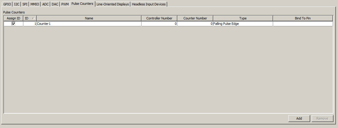
A pulse counter tracks the number of pulses sent to a device. To specify a custom pulse counter, you must add a channel to the Pulse Counters window, as shown in Figure 5-28.
Figure 5-28 The Pulse Counters Custom Device Screen
To add custom Pulse Counter:
Click Add. This adds a new row to the Pulse Counters table.
To define individual settings in a row for your custom device, double-click in a cell to enter a value for that field.
Once you are satisfied with your custom entries, click OK
To remove a channel, select a row and click Remove.
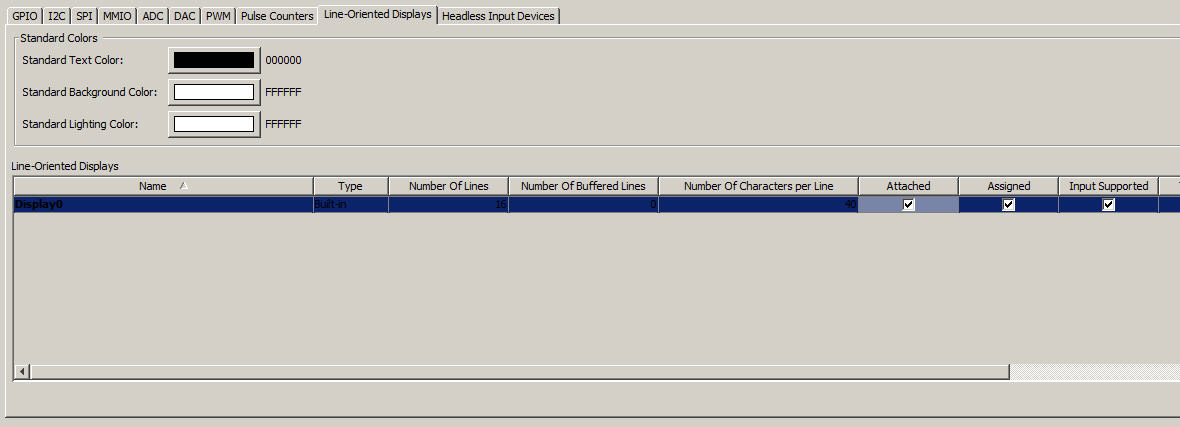
Configuring a line-oriented display allows you to customize a simple user interface in emulation. To customize a line-oriented display, use the Line-Oriented Displays tab in the Custom Device Editor, as show in Figure 5-29.
Figure 5-29 The Line-Oriented Display Custom Device Screen
To configure a new Line-Oriented Display custom device:
Set the following Standard Colors:
Standard Text Color. The default color for text is black (000000 in Hexadecimal). To change the text color, click on the rectangle. This displays the Standard Text Color form, as shown in Figure 5-30.
To set text to a specific color, select the color square from the color map and click OK. Or, click on the following tabs to customize text color based on a variety of sliding-scale color values:
HSV. Allows you to customize Hue, Saturation, and Value fields.
HSL. Allows you to customize Hue, Saturation, and Lightness fields.
RGB. Allows you to customize Red, Green, and Blue fields.
CMYK. Allows you to customize Cyan, Magenta, and Yellow fields.
Standard Background Color. The default background color for is white (FFFFFF in Hexadecimal). To change the background color, click on the rectangle. This displays the Standard Background Color form (same as the Standard Text Color form).
Select a background color and click OK. When the color is changed, the new color value is displayed in Hex.
Standard Lighting Color. The default lighting (highlighting) color is white (FFFFFF in Hexadecimal). To change the lighting color, click on the rectangle. This displays the Standard Lighting Color form (same as the Standard Text Color form).
Select a lighting color and click OK. When the color is changed, the new color value is displayed in Hex.
Click Add. This adds a new row to the Line-Oriented Displays table.
To define individual settings in a row for your custom device, double-click in a cell to enter a value for that field.
|
Note: The Line-Oriented Display Custom Device Screen has many settings that scroll to the right. To fully configure your custom implementation, ensure that all the cells in the new row have been defined. |
Once you are satisfied with your custom entries, click OK
To remove a Line-Oriented Displays, select a row and click Remove.
A headless input device could be buttons, for example, on an embedded hardware device, or other entry devices not connected to a monitor or screen. To add a custom Headless Input Device, do the following:
Click Add. This adds a new row to the Headless Input Devices table.
To define individual settings in a row for your custom device, double-click in a cell to enter a value for that field.
Once you are satisfied with your custom entries, click OK
To remove a channel, select a row and click Remove.
Custom devices should always be managed using the Custom Device Editor. Using the tool ensures that your device can be detected and integrated with the Oracle Java ME SDK 8 EA 2.
New. Select a platform and click New to add a new device.
Edit. Select a device to change, and click Edit.
Clone. Select a device to copy, and click Clone. To prevent confusion, be sure to provide a unique name.
Remove. Select a device to delete and click Remove. This action completely deletes the device.
Import. Select a .zip file created with the Export command and click Import.
Export. Select one or more devices to save, and click Export.
An exported device is stored in a .zip file and saved to any location the user chooses.
The configuration of all peripherals, except UART, can be inspected in the emulator main window. The configuration of UART is defined by the hardware configuration of the COM ports on your Windows 7 PC.
For more information on connecting to a UART Device, see "Connecting to a UART Device."
To open a serial port, such as COM1 or COM2, in Windows you can use the Device Connections Manager. In application code, you can use Connector.open("comm:COM1")
To utilize the Universal Asynchronous Receiver/Transmitter (UART) functionality, you need to create a configuration file as shown here:
javacall\configuration\ojwc\win32\properties_deviceaccess_at.xml
The configuration of the hardware device name for the UART ports on your Windows 7 PC is made up of two settings:
The deviceNumber property of UARTDeviceConfiguration
The system property of device.uart.prefix
For example, if UARTDeviceConfiguration.deviceNumber = 1 and device.uart.prefix = COM, then the hardware device name is COM1.
For an already opened UART, you can add it to the peripheral manager by calling PeripheralManager.open with the configuration object.
The Oracle Java ME SDK 8 EA 2 EmbeddedDevice1 emulator provides support for additional peripherals, ATDevice and Watchdog timers. Use the following configuration settings to open them using the PeripheralManager:
Watchdog Timers. There are two Watchdog timers on the EmbeddedDevice1 emulator with the following configurations:
Device Name: WDG, ID: 30, Hardware Timer's Number: 1
(This is a regular watchdog timer.)
Device Name: WWDG, ID: 31, Hardware Timer's Number: 2
(This is a windowed watchdog timer).
Watchdog timers provide the services to track how your application functions. Because no hardware is available on win32, all running applications are killed when the Watchdog event is fired.
ATDevice. ATDevice is a simple AT commands-based device on the EmbeddedDevice1 emulator that responds "Ok" to any command. It has the following configuration:
Device Name. EMUL, ID: 13, Device Number: 1, Hardware Channel's Number: 1