12 Creating MAF AMX Pages
This chapter describes how to create the MAF Application Mobile XML (MAF AMX) application feature.
This chapter includes the following sections:
12.1 Introduction to the MAF AMX Application Feature
MAF AMX is a subframework within Mobile Application Framework (MAF) that provides a set of UI components that enable you to create an application feature whose behavior is identical on all supported platforms. MAF AMX allows you to use UI components declaratively by dragging them onto a page editor. A typical MAF AMX application feature includes several interconnected pages that can be navigated through various paths.
The MAF AMX Application feature lets you create two kinds of objects that, taken together, perform the function of your application:
-
Views, which perform a function that you define and display information for the user; and
-
Task flows, which define the user's navigation through the different views that you create.
Note:
When developing interfaces for mobile devices, always be aware of the fact that the screen space is very limited. In addition, touchscreen support is not available on some mobile devices.For more information, see the following:
-
Chapter 2, "Getting Started with MAF Application Development"
-
Chapter 14, "Using Bindings and Creating Data Controls in MAF AMX"
Note:
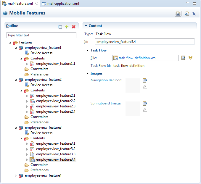
When using the MAF Feature editor to create objects as part of an application, OEPE creates an ID for the object that cannot be changed later.12.2 Creating Task Flows
Task flows allow you to define the navigation between MAF AMX pages. Using your application workspace in OEPE (see Section 2.2, "Creating a MAF Application"), you can start creating the user interface for your MAF AMX application feature by designing task flows. MAF AMX uses navigation cases and rules to define the task flow. These definitions are stored in a file with the default name of task-flow-definition.xml (see Section 12.2.3, "What You May Need to Know About the task-flow-definition.xml File").
A MAF sample application called Navigation (select File > New > MAF Examples, then select Navigation) demonstrates how to use various navigation techniques, such as circular navigation, routers, and so on.
MAF enables you to create MAF AMX application features that have both bounded and unbounded task flows. As described in Section 12.2.12, "What You May Need to Know About Bounded and Unbounded Task Flows," a bounded task flow is also known as a task flow definition and represents the reusable portion of an application. In MAF, bounded task flows have a single entry point and no exit points. They have their own collections of activities and control-flow rules, as well as their own memory scope and managed-bean life span. Other characteristics of bounded task flows include accepting input parameters (see Section 12.2.12.3.1, "Passing Parameters to a Bounded Task Flow") and generating return values (see Section 12.2.12.3.2, "Configuring a Return Value from a Bounded Task Flow").
You use the MAF AMX Task Flow Designer to create bounded task flows for your application feature. This tool includes a diagrammer (see Section 12.2.4, "What You May Need to Know About the MAF Task Flow Diagrammer") in which you build the task flow by dragging and dropping activities and control flows (see Section 12.2.2, "What You May Need to Know About Task Flow Activities and Control Flows") from the Palette. You then define these activities and the transitions between them using the Properties window.
Unless a task flow has already been created, MAF automatically generates a default unbounded task flow (adfc-mobile-config.xml file) when a new MAF AMX page is created.
12.2.1 How to Create a Task Flow
A task flow is composed of the task flow itself and a number of activities with control flow rules between those activities (see Section 12.2.2, "What You May Need to Know About Task Flow Activities and Control Flows"). Typically, the majority of the activities are view activities which represent different pages in the flow. When a method or operation needs to be called (for example, before a page is rendered), you use a method call activity with a control flow case from that activity to the appropriate next activity. When you want to call another task flow, you use a task flow call activity. If the flow requires branching, you use a router activity. At the end of a bounded task flow, you use a return activity which allows the flow to exit and control is sent back to the flow that called this bounded task flow.
You can use the Palette to declaratively create a bounded task flow for your MAF AMX application feature by dragging and placing task flow elements in the flow structure. When you place these elements in relation to one another, OEPE creates the XML metadata needed for navigation to work in your MAF AMX application feature in the task-flow-definition.xml file (default). You can also edit the task flow definition file's source.
To design a task flow, the MAF application must include a View Controller project file (see Chapter 2, "Getting Started with MAF Application Development").
To create a task flow in OEPE, create a bounded task flow from the MAF Features Editor. For more information, see Section 6.2, "How to Define the Application Feature Content as Remote URL or Local HTML."
Additionally, you can manually add elements to the task flow file by directly editing the page in the Source editor. To open the file in the Source editor, click the Source tab.
Note:
When manually editing the task flow file, keep in mind that all the document file names referring to MAF AMX pages, Java Script files, and CSS files are case-sensitive.If special characters (such as an underscore, for example) are used in a file name, you should consult the mobile device specification to verify whether or not the usage of this character is supported.
Once the navigation for your MAF AMX application feature is defined, you can create the pages and add the components that will execute the navigation. For more information about using navigation components on a page, see Section 12.2.6, "How to Define Control Flows."
After you define the task flow for the MAF AMX application feature, you can double-click a view file to access the MAF AMX view. For more information, see Section 12.3, "Creating Views."
12.2.2 What You May Need to Know About Task Flow Activities and Control Flows
A task flow consists of activities and control flow cases that define the transitions between activities.
The MAF Task Flow designer supports activities listed in Table 12-1.
Table 12-1 Task Flow Activities
| Activity | Description |
|---|---|
|
View |
Displays an MAF AMX page. For more information, see Section 12.2.5.1, "Adding View Activities." |
|
Method Call |
Invokes a method (typically a method on a managed bean). You can place a method call activity anywhere in the control flow of an MAF AMX application feature to invoke logic based on control flow rules. For additional information, see Section 12.2.5.3, "Adding Method Call Activities." You can also specify parameters that you pass into a method call that is included in a task flow. These include standard parameters for a method call action in an MAF AMX task flow. When you use the designer to generate a method, it adds the required arguments and type. At runtime, you can define parameters for a method call in a task flow and pass parameters into the method call itself for its usage. For more information, see Part , "How to Add and Use Task Flow Activities." |
|
Router |
Evaluates an Expression Language (EL) expression and returns an outcome based on the value of the expression. These outcomes can then be used to route control to other activities in the task flow. For more information, see Section 12.2.5.2, "Adding Router Activities." |
|
Task Flow Call |
Calls a bounded task flow from either an unbounded or bounded task flow. While a task flow call activity allows you to call a bounded task flow located within the same MAF AMX application feature, you can also call a bounded task flow from a different MAF AMX application feature or from a Feature Archive file (FAR) that has been added to a library. The task flow call activity supports task flow input parameters and return values. For more information, see Section 12.2.5.4, "Adding Task Flow Call Activities." |
|
Task Flow Return |
Identifies the point in an application's control flow where a bounded task flow completes and sends control flow back to the caller. You can use a task flow return only within a bounded task flow. For more information, see Section 12.2.5.5, "Adding Task Flow Return Activities." |
The MAF Task Flow designer supports control flows listed in Table 12-2.
| Control Flow | Description |
|---|---|
|
Control Flow Case |
Identifies how control passes from one activity to the next in the MAF AMX application feature. For more information, see Section 12.2.6.1, "Defining a Control Flow Case." |
|
Wildcard Control Flow Rule |
Represents a control flow case that can originate from any activities whose IDs match a wildcard expression.For more information, see Section 12.2.6.2, "Adding a Wildcard Control Flow Rule." |
12.2.3 What You May Need to Know About the task-flow-definition.xml File
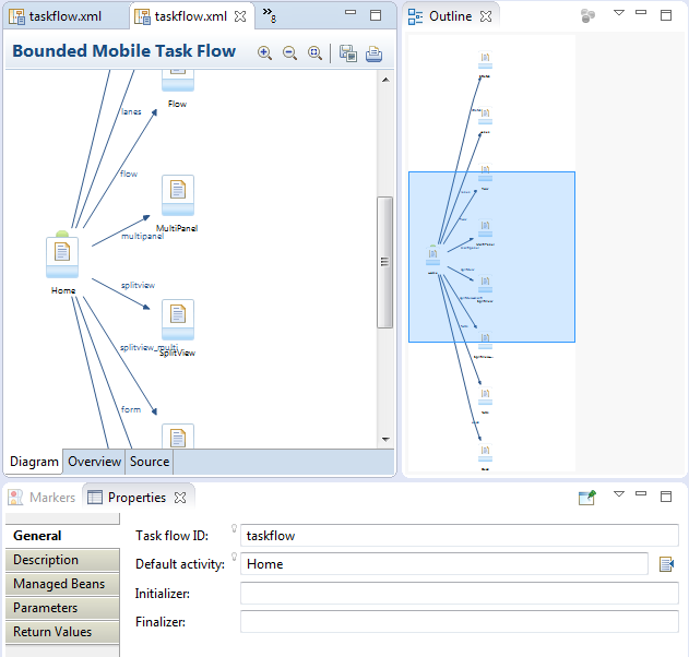
The task-flow-definition.xml file enables you to design the interactions between views (MAF AMX pages) by dragging and dropping task flow components from the Palette onto the diagrammer.
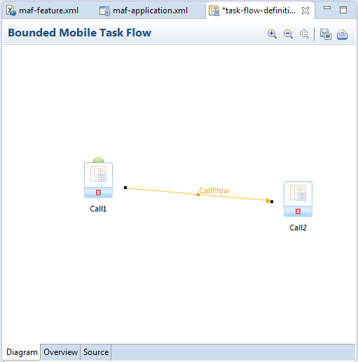
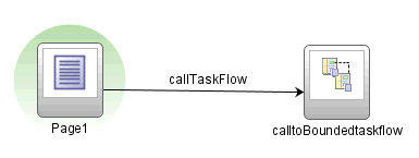
Figure 12-2 shows a sample task flow file called task-flow-definition.xml. In this file, the control flow is directed from Call1 to Call2 by the task flow call CallFlow. (See Section 12.2.7, "What You May Need to Know About MAF Support for Back Navigation").
12.2.4 What You May Need to Know About the MAF Task Flow Diagrammer
As illustrated in Figure 12-2, the task flow diagram and Palette display automatically after you create a task flow using the MAF Task Flow Creation utility. The task flow diagram is a visual editor onto which you can drag and drop activities and task flows from the Palette. You can also edit the task flow file directly, by clicking the Source tab shown in Figure 12-2. For more information, see Section 12.2.5, "How to Add and Use Task Flow Activities."
12.2.5 How to Add and Use Task Flow Activities
You use the task flow diagrammer, selecting options from the Palette, to drag and drop activities, views, and control flows.
To add an activity to an MAF task flow:
-
In the Project Explorer, double-click a task flow source file (such as
task-flow-definition.xml) to display the task flow diagram and the Palette. The diagrammer displays the task flow editor. The Palette automatically displays the components available for an MAF task flow. -
Drag an activity from the Palette onto the diagram.
Note:
There is a default activity that is associated with each bounded task flow.12.2.5.1 Adding View Activities
One of the primary types of task flow activity is the view activity which displays an MAF AMX page.
XML metadata in the source file of the task flow associates a view activity with a physical MAF AMX page. An id attribute identifies the view activity.
You can configure view activities in your task flow to pass control to each other at runtime. For example, to pass control from one view activity (view activity A) to a second view activity (view activity B), you could configure a command component, such as a Button or a Link on the page associated with view activity A. To do so, you set the command component's Action attribute to the control flow case from-outcome that corresponds to the task flow activity that you want to invoke (for example, view activity B). At runtime, the end user initiates the control flow case by invoking the command component. It is possible to navigate from a view activity to another activity using either a constant or dynamic value on the Action attribute of the UI component:
-
A constant value of the component's Action attribute is an action outcome that always triggers the same control flow case. When an end user clicks the component, the activity specified in the control flow case is performed. There are no alternative control flows.
-
A dynamic value of the component's Action attribute is bound to a managed bean or a method. The value returned by the method binding determines the next control flow case to invoke. For example, a method might verify user input on a page and return one value if the input is valid and another value if the input is invalid. Each of these different action values trigger different navigation cases, causing the application to navigate to one of two possible target pages.
For more information, see Section 12.2.9, "How to Specify Action Outcomes Using UI Components."
You can also write an EL expression that must evaluate to true before control passes to the target view activity. You write the EL expression as a value for the <if> child element of the control flow case in the task flow.
Example 12-1 and Example 12-2 demonstrate what happens when you pass control between View activities:
Example 12-1 shows a control flow case defined in the XML source file for a bounded or unbounded task flow.
Example 12-1 Control Flow Case Defined in XML Source File
<control-flow-rule>
   <from-activity-id>Start</from-activity-id>
      <control-flow-case>
         <from-outcome>toOffices</from-outcome>
         <to-activity-id>WesternOffices</to-activity-id>
      </control-flow-case>
</control-flow-rule>
As Example 12-2 shows, a Button on an MAF AMX page associated with the Start view activity specifies toOffices as the action attribute. When the end user clicks the button, control flow passes to the WesternOffices activity specified as the to-activity-id in the control flow metadata.
Example 12-2 Static Navigation Button Defined in a View Activity
<amx:commandButton text="Go" id="b1" action="toOffices">
For more information, see the following:
As previously stated, the view activity is associated in metadata with an actual MAF AMX page which it displays when added to a task flow. You add a view activity by dragging and dropping it from the Palette. You can create an actual MAF AMX page by right-clicking the View activity in the Diagram window and then define characteristics for the page through the displayed dialog (see Figure 12-15, "Create New MAF Page Dialog").
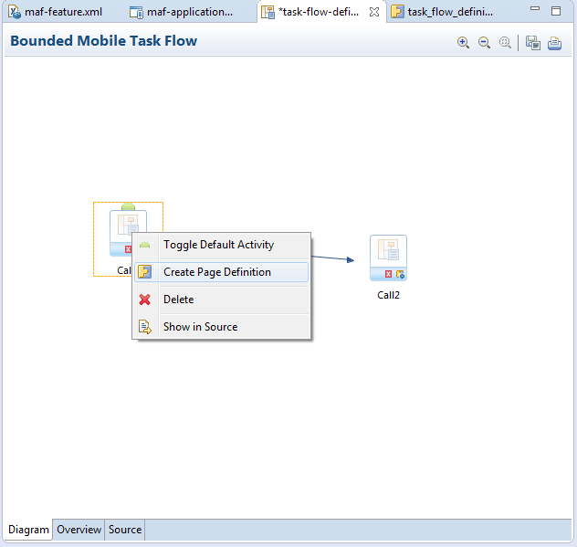
If you are creating a bounded task flow, you may want to designate a specific activity as the default activity (see Section 12.2.12, "What You May Need to Know About Bounded and Unbounded Task Flows"). This allows the specific activity to execute first whenever the bounded task flow runs. By default, OEPE makes the first activity you add to the task flow the default. To change to a different activity, right-click the appropriate activity in the Diagram window and choose Create Page Definition (see Figure 12-3).
12.2.5.2 Adding Router Activities
You use a router activity to route control to activities based on the runtime evaluation of EL expressions.
Each control flow corresponds to a different router case. Each router case uses the following elements to choose the activity to which control is next routed:
-
expression: an EL expression that evaluates totrueorfalseat runtime.The router activity returns the outcome that corresponds to the EL expression that returns
true. -
outcome: a value returned by the router activity if the EL expression evaluates totrue.If the router case
outcomematches afrom-outcomeon a control flow case, control passes to the activity that the control flow case points to. If none of the cases for the router activity evaluate totrue, or if no router activity cases are specified, theoutcomespecified in the router Default Outcome field (if any) is used.
Consider using a router activity if your routing condition can be expressed in an EL expression: the router activity allows you to show more information about the condition on the task flow.
When you drag a Router activity onto the diagram, you can use the Properties window to create an expression whose evaluation determines which control flow rule to follow. Using the Properties window, you configure the Activity ID and Default Outcome properties of the router activity and add router cases to the router activity.
When defining the Activity ID attribute, write a value that identifies the router activity in the task flow's source file.
When defining the Default Outcome attribute, specify an activity that the router activity passes control to if no control flow cases evaluate to true or if no control flow case is specified.
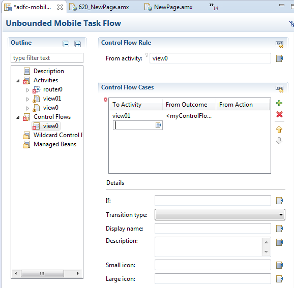
For each router case that you add, specify values by clicking Add ( + ) in the Control Flow Cases section, as shown in Figure 12-4.
-
Expression: An EL expression that evaluates to
trueorfalseat runtime.For example, to reference the value in an input text field of a view activity, write an EL expression similar to the following:
#{pageFlowScope.value=='view2'}If this EL expression returns
true, the router activity invokes the outcome that you specify in the Outcome field. -
Outcome: The outcome the router activity invokes if the EL expression specified by Expression returns
true.Create a control flow case or a wildcard control flow rule for each outcome in the diagram of your task flow. For example, for each outcome in a control flow case, ensure that there is a corresponding
from-outcome.
When you configure the control flow using a router activity, OEPE writes values to the source file of the task flow based on the values that you specify for the properties of the router activity.
12.2.5.3 Adding Method Call Activities
When you drag a Method Call activity onto the diagram, you can use the New Object dialog to choose the method to call.
Use a method call activity to call a custom or built-in method that invokes the MAF AMX application feature logic from anywhere within the application feature's control flow. You can specify methods to perform tasks such as initialization before displaying a page, cleanup after exiting a page, exception handling, and so on.
You can set an outcome for the method that specifies a control flow case to pass control to after the method finishes. You can specify the outcome as one of the following:
-
fixed-outcome: upon successful completion, the method always returns this single outcome, for example,success. If the method does not complete successfully, an outcome is not returned. If the method type is void, you must specify afixed-outcomeand cannot specifyto-string.You define this outcome by setting the Fixed Outcome field in the Properties window.
-
to-string: if specified astrue, the outcome is based on calling thetoStringmethod on the Java object returned by the method. For example, if thetoStringmethod returnseditBasicInfo, navigation goes to a control flow case namededitBasicInfo.You define this outcome by setting the toString() field in the Properties window.
You can associate the method call activity with an existing method by dropping a data control operation from the Data Controls window directly onto the method call activity in the task flow diagram. You can also drag methods and operations directly to the task flow diagram: a new method call activity is created automatically when you do so. You can specify an EL expression and other options for the method.
You configure the method call by modifying its activity identifier in the Activity ID field if you want to change the default value. If you enter a new value, the new value appears under the method call activity in the diagram.
In the Method field, enter an EL expression that identifies the method to call. Note that the bindings variable in the EL expression references a binding from the current binding container. In order to specify the bindings variable, you must specify a binding container definition or page definition. For more information, see Section 12.3.2.3.5, "What You May Need to Know About Generated Drag and Drop Artifacts."
You can also use the Expression Builder to build the EL expression for the method:
-
Choose Method Expression Builder from the Property Editor for the Method field.
-
In the Expression Builder dialog, navigate to the method that you want to invoke and select it.
If the method call activity is to invoke a managed bean method, double-click the method call activity in the diagram. This invokes a dialog where you can specify the managed bean method you want to invoke.
You can specify parameters and return values for a method by using the Parameters section of the Properties window. If parameters have not already been created by associating the method call activity to an existing method, add the parameters by clicking Add ( + ) and setting the following:
-
Class: enter the parameter class. For example,
java.lang.Double. -
Value: enter an EL expression that retrieves the value of the parameter. For example:
#{pageFlowScope.shoppingCart.totalPurchasePrice} -
Return Value: enter an EL expression that identifies where to store the method return value. For example:
#{pageFlowScope.Return}
12.2.5.4 Adding Task Flow Call Activities
You can use a task flow call activity to call a bounded task flow from either the unbounded task flow (see Section 12.2.12.1, "Unbounded Task Flows") or a bounded task flow (see Section 12.2.12.2, "Bounded Task Flows"). This activity allows you to call a bounded task flow located within the same or a different MAF AMX application feature.
The called bounded task flow executes its default activity first. There is no limit to the number of bounded task flows that can be called. For example, a called bounded task flow can call another bounded task flow, which can call another, and so on resulting in the creation of chained task flows where each task flow is a link in a chain of tasks.
To pass parameters into a bounded task flow, you must specify input parameter values on the task flow call activity. These values must correspond to the input parameter definitions on the called bounded task flow. For more information, see Section 12.2.5.4.2, "Specifying Input Parameters on a Task Flow Call Activity."
Note:
The value on the task flow call activity input parameter specifies the location within the calling task flow from which the value is to be retrieved.The value on the input parameter definition for the called task flow specifies where the value is to be stored within the called bounded task flow once it is passed.
Note:
When a bounded task flow is associated with a task flow call activity, input parameters are automatically inserted on the task flow call activity based on the input parameter definitions set on the bounded task flow. Therefore, you only need to assign values to the task flow call activity input parameters.By default, all objects are passed by reference. Primitive types (for example, int, long, or boolean) are always passed by value.
The technique for passing return values out of the bounded task flow to the caller is similar to the way that input parameters are passed. For more information, see Section 12.2.12.3.2, "Configuring a Return Value from a Bounded Task Flow."
To use a task flow call activity:
-
Call a bounded task flow using a task flow call activity (see Section 12.2.5.4.1, "Calling a Bounded Task Flow Using a Task Flow Call Activity")
-
Specify input parameters on a task flow call activity if you want to pass parameters into the bounded task flow (see Section 12.2.5.4.2, "Specifying Input Parameters on a Task Flow Call Activity").
12.2.5.4.1 Calling a Bounded Task Flow Using a Task Flow Call Activity
Add a task flow call activity to the calling bounded or unbounded task flow to call a bounded task flow.
-
Open a bounded task flow file in the Diagram view.
-
From the Activities pane of the Palette, drag and drop a Task Flow Call activity onto the diagram.
-
Choose one of the following options to identify the called task flow:
-
Double-click the newly-dropped task flow call activity to open the Create MAF Task Flow dialog where you define settings for a new bounded task flow.
-
Drag an existing bounded task flow from the Project Explorer and drop it on the task flow call activity.
-
If you know the name of the bounded task flow that you want to invoke, perform the following steps:
-
In the Diagram view, select the Task Flow Call activity.
-
In the Properties window, expand the General section, and select Static from the Task Flow Reference list.
-
In the Document field, enter the name of the source file for the bounded task flow to call.
-
In the ID field, enter the bounded task flow ID contained in the XML source file for the called bounded task flow (see Figure 12-5).
-
-
If you do not know the name of the bounded task flow to invoke and it is dependent on an end user selection at runtime, perform the following steps:
-
In the Diagram view, select the Task Flow Call activity.
-
In the Properties window, expand the General section, and select Dynamic from the Task Flow Reference list.
-
Use the Expression Builder to set the value of the Dynamic Task Flow Reference property field: write an EL expression that identifies the ID of the bounded task flow to invoke at runtime.
-
-
12.2.5.4.2 Specifying Input Parameters on a Task Flow Call Activity
The suggested method for mapping parameters between a task flow call activity and its called bounded task flow is to first specify input parameter definitions for the called bounded task flow. Then you can drag the bounded task flow from the Project Explorer and drop it on the task flow call activity. The task flow call activity input parameters are created automatically based on the bounded task flow's input parameter definition. For more information, see Section 12.2.12.3.1, "Passing Parameters to a Bounded Task Flow."
You can, of course, first specify input parameters on the task flow call activity. Even if you have defined them first, they will automatically be replaced based on the input parameter definitions of the called bounded task flow, once it is associated with the task flow call activity.
If you have not yet created the called bounded task flow, you may still find it useful to specify input parameters on the task flow call activity. Doing so at this point allows you to identify any input parameters you expect the task flow call activity to eventually map when calling a bounded task flow.
-
Open a task flow file in the Diagram view and select a Task Flow Call activity.
-
In the Properties window, expand the Parameters section, and click Add ( + ) to specify a new input parameter in the Input Parameters list as follows:
-
Name: enter a name to identify the input parameter.
-
Value: enter an EL expression that identifies the parameter value. The EL expression identifies the location within the calling task flow from which the parameter value is to be retrieved. For example, enter an EL expression similar to the following:
#{pageFlowScope.callingTaskflowParm}By default, all objects are passed by reference. Primitive types (for example,
int,long, orboolean) are always passed by value.
-
-
After you have specified an input parameter, you can specify a corresponding input parameter definition for the called bounded task flow. For more information, see Section 12.2.12.3.1, "Passing Parameters to a Bounded Task Flow."
12.2.5.5 Adding Task Flow Return Activities
A task flow return activity identifies the point in an MAF AMX application feature's control flow where a bounded task flow completes and sends control flow back to the caller. You can use a task flow return activity only within a bounded task flow.
A gray circle around a task flow return activity icon indicates that the activity is an exit point for a bounded task flow. A bounded task flow can have zero or more task flow return activities.
Each task flow return activity specifies an outcome that it returns to the calling task flow.
The outcome returned to an invoking task flow depends on the end user action. You can configure control flow cases in the invoking task flow to determine the next action by the invoking task flow. Set the From Outcome property of a control flow case to the value returned by the task flow return activity's outcome to invoke an action based on that outcome. This determines control flow upon return from the called task flow.
To add a task flow return activity:
-
Open a bounded task flow file in the Diagram view.
-
From the Activities pane of the Palette, drag and drop a Task Flow Return activity onto the diagram.
-
In the Properties window, expand the General section and enter an outcome in the Name field.
The task flow return activity returns this outcome to the calling task flow when the current bounded task flow exits. You can specify only one outcome per task flow return activity. The calling task flow should define control flow rules to handle control flow upon return. For more information, see Section 12.2.6, "How to Define Control Flows."
-
Expand the Behavior section and choose one of the options in the Reentry list.
If you specify reentry-not-allowed on a bounded task flow, an end user can still click the back button on the mobile device and return to a page within the bounded task flow. However, if the end user does anything on the page such as activating a button, an exception (for example,
InvalidTaskFlowReentry) is thrown indicating the bounded task flow was reentered improperly. -
In the End Transaction drop down list, choose one of the following options:
-
commit: select to commit the existing transaction to the database.
-
rollback: select to roll back the transaction to what it was on entry of the called task flow. This has the same effect as canceling the transaction, since it rolls back a new transaction to its initial state when it was started on entry of the bounded task flow.
If you do not specify commit or rollback, the transaction is left open to be closed by the calling bounded task flow.
-
12.2.5.6 Using Task Flow Activities with Page Definition Files
Page definition files define the binding objects that populate data at runtime. They are typically used in an MAF AMX application feature to bind page UI components to data controls. The following task flow activities can also use page definition files to bind to data controls:
-
Method call: You can drag and drop a data control operation from the Data Controls window onto a task flow to create a method call activity or onto an existing method call activity. In both cases, the method call activity binds to the data control operation.
-
Router: associating a page definition file with a router activity creates a binding container. At runtime, this binding container makes sure that the router activity references the correct binding values when it evaluates the router activity cases' EL expressions. Each router activity case specifies an outcome to return if its EL expression evaluates to
true. For this reason, only add data control operations to the page definition file that evaluate totrueorfalse. -
Task flow call: associating a page definition file with a task flow call activity creates a binding container. At runtime, the binding container is in context when the task flow call activity passes input parameters. The binding container makes sure that the task flow call activity references the correct values if it references binding values when passing input parameters from a calling task flow to a called task flow.
-
View: you cannot directly associate a view activity with a page definition file. Instead, you associate the page that the view activity references.
If you right-click any of the preceding task flow activities, except view activity, in the Diagram window for a task flow, OEPE displays an option on the context menu that enables you to create a page definition file if one does not yet exist. If a page definition file does exist, OEPE displays a context menu option for all task flow activities to go to the page definition file (see Section 12.3.1.5, "Accessing the Page Definition File"). OEPE also displays the Edit Binding context menu option when you right-click a method call activity that is associated with a page definition file.
A task flow activity that is associated with a page definition file displays an icon in the lower-right section of the task flow activity icon.
To associate a page definition file with a task flow activity:
-
In the Diagram view, right-click the task flow activity for which you want to create a page definition file and select Create Page Definition from the context menu.
-
In the resulting page definition file, add the bindings that you want your task flow activity to reference at runtime.
For more information about page definition files, see Section 12.3.2.3.5, "What You May Need to Know About Generated Drag and Drop Artifacts."
When the preceding steps are completed, OEPE generates a page definition file for the task flow activity at design time. The file name of the page definition file comprises the originating task flow and either the name of the task flow activity or the data control operation to invoke. OEPE also generates an EL expression from the task flow activity to the binding in the created page definition file. At runtime, a binding container ensures that a task flow activity's EL expressions reference the correct value.
12.2.6 How to Define Control Flows
You use the following task flow components to define the control flow in your MAF AMX application feature:
-
Control Flow Case (see Section 12.2.6.1, "Defining a Control Flow Case")
-
Wildcard Control Flow Rule (see Section 12.2.6.2, "Adding a Wildcard Control Flow Rule")
12.2.6.1 Defining a Control Flow Case
You can create navigation using the Control Flow Case component, which identifies how control passes from one activity to the next. To create a control flow, select Control Flow Case from the Palette. Next, connect the Control Flow Case to the source activity, and then to the destination activity. OEPE creates the following after you connect a source and target activity:
-
control-flow-rule: Identifies the source activity using afrom-activity-id. -
control-flow-case: Identifies the destination activity using ato-activity-id.
To define a control flow case directly in the MAF task flow diagram:
-
Open the task flow source file in the Diagram view.
-
Select Control Flow Case from the Palette.
-
On the diagram, click a source activity and then a destination activity. OEPE adds the control flow case to the diagram. Each line that OEPE adds between an activity represents a control flow case. The
from-outcomecontains a value that can be matched against values specified in the action attribute of the MAF AMX UI components. -
To change the
from-outcome, select the text next to the control flow in the diagram. By default, this is a wildcard character. -
To change the
from-activity-id(the identifier of the source activity), or theto-activity-id(the identifier for the destination activity), drag either end of the arrow in the diagram to a new activity.
12.2.6.2 Adding a Wildcard Control Flow Rule
MAF task flows support the wildcard control flow rule, which represents a control flow from-activity-id that contains a trailing wildcard (foo*) or a single wildcard character. You can add a wildcard control flow rule to an unbounded or bounded task flow by dragging and dropping it from the Palette. To configure your wildcard control flow rule, use the Properties window.
To add a wildcard control flow rule:
-
Open the task flow source file in the Diagram view.
-
Select Wildcard Control Flow Rule in the Palette and drop it onto the diagram.
-
Select Control Flow Case in the Palette.
-
In the task flow diagram, drag the control flow case from the wildcard control flow rule to the target activity, which can be any activity type.
-
By default, the label below the wildcard control flow rule is *. This is the value for the From Activity ID element. To change this value, select the wildcard control flow rule in the diagram. In the Properties window for the wildcard control flow rule, enter a new value in the From Activity ID field. A useful convention is to cast the wildcard control flow rule in a form that describes its purpose. For example, enter
project*. The wildcard must be a trailing character in the new label.Tip:
You can also change the From Activity ID value in the task flow diagram. -
Optionally, in the Properties window expand the Behavior section and write an EL expression in the If field that must evaluate to
truebefore control can pass to the activity identified by To Activity ID.
12.2.6.3 What You May Need to Know About Control Flow Rule Metadata
Example 12-3 shows the general syntax of a control flow rule element in the task flow source file.
Example 12-3 Control Flow Rule Definition
<control-flow-rule>
   <from-activity-id>from-view-activity</from-activity-id>
   <control-flow-case>
      <from-action>actionmethod</from-action>
      <from-outcome>outcome</from-outcome>
      <to-activity-id>destinationActivity</to-activity-id>
      <if>#{myBean.someCondition}</if>
   </control-flow-case>
   <control-flow-case>
   ...
   </control_flow-case>
</control-flow-rule>
Control flow rules can consist of the following metadata:
-
control-flow-rule: a mandatory wrapper element for control flow case elements. -
from-activity-id: the identifier of the activity where the control flow rule originates (for example,source).A trailing wildcard ( * ) character in
from-activity-idis supported. The rule applies to all activities that match the wildcard pattern. For example,login*matches any logical activity ID name beginning with the literallogin. If you specify a single wildcard character in the metadata (not a trailing wildcard), the control flow automatically converts to a wildcard control flow rule activity in the diagram. For more information, see Section 12.2.6.2, "Adding a Wildcard Control Flow Rule." -
control-flow-case: a mandatory wrapper element for each case in the control flow rule. Each case defines a different control flow for the same source activity. A control flow rule must have at least one control flow case. -
from-action: an optional element that limits the application of the rule to outcomes from the specified action method. The action method is specified as an EL binding expression, such as, for example,#{backing_bean.cancelButton_action}.In Example 12-3, control passes to
destinationActivityonly if outcome is returned fromactionmethod.The value in
from-actionapplies only to a control flow originating from a view activity, not from any other activity types. Wildcards are not supported infrom-action. -
from-outcome: identifies a control flow case that will be followed based on a specific originating activity outcome. All possible originating activity outcomes should be accommodated with control flow cases.If you leave both the
from-actionand thefrom-outcomeelements empty, the case applies to all outcomes not identified in any other control flow cases defined for the activity, thus creating a default case for the activity. Wildcards are not supported infrom-outcome. -
to-activity-id: a mandatory element that contains the complete identifier of the activity to which the navigation is routed if the control flow case is performed. Each control flow case can specify a differentto-activity-id. -
if: an optional element that accepts an EL expression as a value. If the EL expression evaluates totrueat runtime, control flow passes to the activity identified by theto-activity-idelement.
12.2.6.4 What You May Need to Know About Control Flow Rule Evaluation
At runtime, task flows evaluate control flow rules from the most specific to the least specific match to determine the next transition between activities. Evaluation is based on the following priority:
-
from-activity-id,from-action,from-outcome: first, searches for a match in all three elements is performed. -
from-activity-id,from-outcome: the search is performed in these elements if no match in all three elements is found. -
from-activity-id: if search in the preceding combinations did not result in a match, search is performed in this element only.
12.2.7 What You May Need to Know About MAF Support for Back Navigation
In the task flow example that Figure 12-6 shows, it is possible to take two separate paths to reach viewD based on the action outcome value (see Section 12.2.9, "How to Specify Action Outcomes Using UI Components"): either from viewA to viewB to viewD, or from viewA to viewC to viewD.
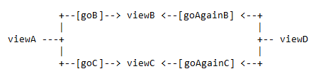
While you could theoretically keep track of which navigation paths had been followed and then directly implement the __back navigation flow, it would be tedious and error-prone, especially considering the fact that due to the limited screen space on mobile devices transitions out of the navigation sequences occur very frequently. MAF provides support for a built-in __back navigation that enables moving back through optional paths across a task flow: by applying its ”knowledge” of the path taken, MAF performs the navigation back through the same path. For example, if the initial navigation occurred from viewA to viewC to viewD, on exercising the __back option on ViewD MAF would automatically take the end user back to ViewA through ViewC rather than through ViewB.
For additional information, see the following:
12.2.8 How to Enable Page Navigation by Dragging
You can enable navigation from one MAF AMX page to another through the use of the Navigation Drag Behavior operation. For more information, see Section 13.3.26, "How to Enable Drag Navigation."
12.2.9 How to Specify Action Outcomes Using UI Components
Using the Properties window, you can specify an action outcome by setting the action attribute of one of the following UI components to the corresponding control flow case from-outcome leading to the next task flow activity:
-
Command Button (see Section 13.3.5, "How to Use Buttons")
-
Command Link (see Section 13.3.6, "How to Use Links")
-
List Item
You use the UI component's Action field to make a selection from a list of possible action outcomes defined in one or more task flow for a specific MAF AMX page.
A Back action (__back) is automatically added to every list to enable navigation to the previously visited page.
Note:
An MAF AMX page can be referenced in both bounded and unbounded task flows, in which case actions outcomes from both task flows are included in the Action selection list.12.2.10 How to Create and Reference Managed Beans
You can create and use managed beans in your MAF application to store additional data or execute custom code. You can use usual editing mechanism to reference managed beans and create references to them for applicable fields. For more information, see Section 14.4, "Creating and Using Managed Beans."
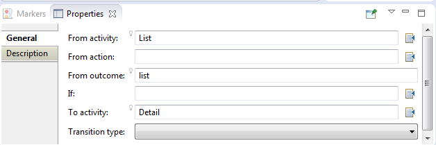
Click on the name of the task flow (not the icon) to invoke the Edit Property dialog that Figure 12-7 shows.
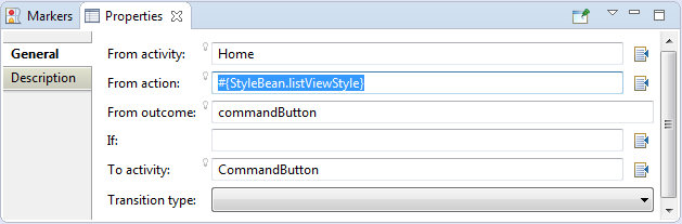
Table 12-5 lists MAF AMX attributes for which the Edit option in the Properties window is available.
Table 12-3 Editable Attributes
| Property | Element |
|---|---|
|
|
|
|
|
|
|
|
|
|
|
|
|
|
|
|
|
|
|
|
|
|
|
|
|
|
|
|
|
|
|
|
|
|
|
|
|
|
|
|
|
|
|
|
|
|
|
|
|
|
|
|
|
|
|
|
|
|
|
|
|
|
|
|
|
|
|
|
|
|
|
|
|
|
|
|
|
|
|
|
|
|
|
|
|
|
|
|
|
|
|
|
|
|
|
|
|
|
|
|
|
|
|
|
|
|
|
|
|
|
|
|
|
|
|
|
|
|
|
|
|
|
|
|
|
|
|
|
|
|
|
|
|
|
|
|
|
|
|
|
|
|
|
|
|
|
|
|
|
|
|
|
|
|
|
|
Clicking Edit for all other properties invokes a similar dialog, but without the Action Outcome option
The preceding dialogs demonstrate that you can either create a managed bean, or select an available action outcome for the action property.
The Action Outcome list shown in Figure 12-7 contains the action outcomes from all task flows to which a specific MAF AMX page belongs. In addition, this list contains a __back navigation outcome to go back to the previously visited page (see Section 12.2.9, "How to Specify Action Outcomes Using UI Components" for more information). If a page is not part of any task flow, the only available outcome in the Action Outcome list is __back. When you select one of the available action outcomes and click OK, the action property value is updated with the appropriate EL expression, such as the following for a commandButton:
<amx:commandButton action="goHome"/>
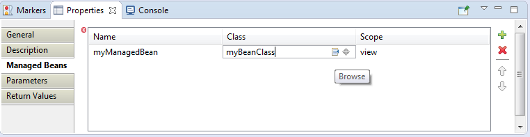
The Method Binding option (see Figure 12-7) allows you to either create a new managed bean class or select an existing one.
To create a new managed bean class:
-
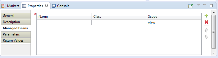
Click New next to the Managed Bean field to open the Create Managed Bean dialog that Figure 12-8 shows.
MAF supports the following scopes:
-
application -
view -
pageFlow
When you declare a managed bean to an MAF application or the MAF AMX application feature, the managed bean is instantiated and identified in the proper scope, and the bean's properties are resolved and its methods are called through EL. For more information, see Section 14.3, "Creating EL Expressions."
-
-
Press the Tab key to proceed from the Name field to the Class name field (see Figure 12-9). You can either type in the class name or click the Browse button to select.
Example 12-4 shows the newly created managed bean class. The task flow that this MAF AMX page is part of is updated to reference the bean.
Example 12-4 New Managed Bean Class
<managed-bean id="__3">
   <managed-bean-name>MyBean</managed-bean-name>
   <managed-bean-class>mobile.MyBean</managed-bean-class>
   <managed-bean-scope>application</managed-bean-scope>
</managed-bean>
Note:
If a given MAF AMX page is part of bounded as well as unbounded task flows, both of these task flows are updated with the managed bean entry. -
Edit the selected property value with the appropriate EL expression, such as the following for a
commandButton:<amx:commandButton action="#{MyBean.getMeHome}"/>The managed bean class is also updated to contain the newly created method, as Example 12-5 shows.
For more information, see the following:
12.2.11 How to Specify the Page Transition Style
By defining the page transition style on the task flow, you can specify how MAF AMX pages transition from one view to another. The behavior of your MAF AMX page at transition can be as follows:
-
fading in
-
sliding in from left
-
sliding in from right
-
sliding up from bottom
-
sliding down from top
-
sliding in from start
-
sliding in from end
-
flipping up from bottom
-
flipping down from top
-
flipping from left
-
flipping from right
-
flipping from start
-
flipping from end
-
none
Sliding in from start and end, as well as flipping from start and end are used on the iOS platform to accommodate the right-to-left text direction. It is generally recommended to use the start and end transition style as opposed to left and right.
Note:
You cannot enable flipping on the Android platform.You set the transition style by modifying the transition attribute of the control-flow-case (Control Flow Case component), as Example 12-6 shows.
Example 12-6 Setting Transition Style
<control-flow-rule id="__1">
   <from-activity-id>products</from-activity-id>
   <control-flow-case id="__2">
      <from-outcome>details</from-outcome>
      <to-activity-id>productdetails</to-activity-id>
      <transition>fade</transition>
   </control-flow-case>
</control-flow-rule>
In the Properties window, the transition attribute is located under Behavior. The default transition style is slideLeft.
Tip:
When defining the task flow, you should specify thecontrol-flow-case's transition value such that it is logical. For example, if the transition occurs from left to right with the purpose of navigating back, then the transition should return to the previous page by sliding right.12.2.12 What You May Need to Know About Bounded and Unbounded Task Flows
Task flows provide a modular approach for defining control flow in an MAF AMX application feature. Instead of representing an application feature as a single large page flow, you can divide it into a collection of reusable task flows. Each task flow contains a portion of the application feature's navigational graph. The nodes in the task flows represent activities. An activity node represents a simple logical operation such as displaying a page, executing application logic, or calling another task flow. The transitions between the activities are called control flow cases.
There are two types of task flows in MAF AMX:
-
Unbounded Task Flows: a set of activities, control flow rules, and managed beans that interact to allow the end user to complete a task. The unbounded task flow consists of all activities and control flows in an MAF AMX application feature that are not included within a bounded task flow.
-
Bounded Task Flows: a specialized form of task flow that, in contrast to the unbounded task flow, has a single entry point and no exit points. It contains its own collections of activities and control-flow rules, as well as their own memory scope and managed-bean life span.
For a description of the activity types that you can add to unbounded or bounded task flows, see Section 12.2.2, "What You May Need to Know About Task Flow Activities and Control Flows."
A typical MAF AMX application feature contains a combination of one unbounded task flow created at the time when the application feature is created and one or more bounded task flows. At runtime, the MAF application can call bounded task flows from activities that you added to the unbounded task flow.
12.2.12.1 Unbounded Task Flows
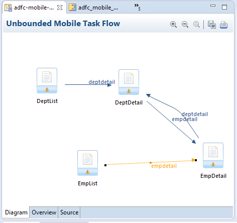
An MAF AMX application feature always contains one unbounded task flow, which provides one or more entry points to that application feature. An entry point is represented by a view activity. By default, the source file for the unbounded task flow is the adfc-mobile-config.xml file.
Note:
Although it is possible create additional source files for unbounded task flows, the MAF AMX application feature combines all source files at runtime into theadfc-mobile-config.xml file.Figure 12-10 displays the diagram for an unbounded task flow from an MAF AMX application feature. This task flow contains a number of view activities that are all entry points to the application feature.
Consider using an unbounded task flow if the following applies:
-
There is no need for the task flow to be called by another task flow.
-
The MAF AMX application feature has multiple points of entry.
-
There is no need for a specifically designated activity to run first in the task flow (default activity).
An unbounded task flow can call a bounded task flow, but cannot be called by another task flow.
12.2.12.2 Bounded Task Flows
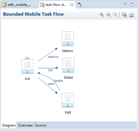
By default, the IDE proposes a file name for the source file of a bounded task flow (see Section 12.2.1, "How to Create a Task Flow"). You can modify this file name to reflect the purpose of the task to be performed.
A bounded task flow can call another bounded task flow, which can call another, and so on. There is no limit to the depth of the calls.
Figure 12-11 displays the diagram for a bounded task flow from an MAF AMX application feature.
The following are reasons for creating a bounded task flow:
-
The bounded task flow always specifies a default activity, which is a single point of entry that must execute immediately upon entry of the bounded task flow.
-
It is reusable within the same or other MAF AMX application features.
-
Any managed beans you use within a bounded task flow can be specified in a page flow scope, making them isolated from the rest of the MAF AMX application feature. These managed beans (with page flow scope) are automatically released when the task flow completes.
The following is a summary of the main characteristics of a bounded task flow:
-
Well-defined boundary: a bounded task flow consists of its own set of private control flow rules, activities, and managed beans. A caller requires no internal knowledge of page names, method calls, child bounded task flows, managed beans, and control flow rules within the bounded task flow boundary. Data controls can be shared between task flows.
-
Single point of entry: a bounded task flow has a single point of entry—a default activity that executes before all other activities in the task flow.
-
Page flow memory scope: you can specify page flow scope as the memory scope for passing data between activities within the bounded task flow. Page flow scope defines a unique storage area for each instance of a bounded task flow. Its lifespan is the bounded task flow, which is longer than request scope and shorter than session scope.
-
Addressable: you can access a bounded task flow by specifying its unique identifier within the XML source file for the bounded task flow and the file name of the XML source file.
-
Reusable: you can identify an entire group of activities as a single entity, a bounded task flow, and reuse the bounded task flow in another MAF AMX application feature within an MAF application.
You can also reuse an existing bounded task flow by calling it.
In addition, you can use task flow templates to capture common behaviors for reuse across different bounded task flows.
-
Parameters and return values: a caller can pass input parameters to a bounded task flow and accept return values from it (see Section 12.2.12.3.1, "Passing Parameters to a Bounded Task Flow" and Section 12.2.12.3.2, "Configuring a Return Value from a Bounded Task Flow").
In addition, you can share data controls between bounded task flows.
-
On-demand loading of metadata: bounded task flow metadata is loaded on demand when entering a bounded task flow.
12.2.12.3 Using Parameters in Task Flows
A task flow´s ability to accept input parameters and return parameter values allows you to manipulate data in task flows and share data between task flows. Using these abilities, you can optimize the reuse of task flows in your MAF AMX application feature.
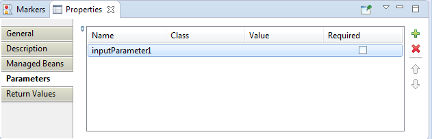
Figure 12-12 shows a task flow that specifies an input parameter definition to hold information about a user in a pageFlow scope.
You can specify parameter values using standard EL expressions if you call a bounded task flow using a task flow call activity. For example, you can specify parameters using the following syntax for EL expressions:
-
#{bindings.bindingId.inputValue} -
#{CustomerBean.zipCode}
Appending inputValue to the EL expression ensures that you assign to the parameter the value of the binding rather than the actual binding object.
12.2.12.3.1 Passing Parameters to a Bounded Task Flow
A called bounded task flow can accept input parameters from the task flow that calls it or from a task flow binding.
To pass an input parameter to a bounded task flow, you specify one or more of the following:
-
Input parameters on the task flow call activity in the calling task flow: input parameters specify where the calling task flow stores parameter values.
-
Input parameter definitions on the called bounded task flow: input parameter definitions specify where the called bounded task flow can retrieve parameter values at runtime.
Specify the same name for the input parameter that you define on the task flow call activity in the calling task flow and the input parameter definition on the called bounded task flow. Do this so you can map input parameter values to the called bounded task flow.
If you do not specify an EL expression to reference the value of the input parameter, the EL expression for value defaults to the following at runtime:
#{pageFlowScope.parmName}
where parmName is the value you entered for the input parameter name.
In an input parameter definition for a called bounded task flow, you can specify an input parameter as required. If the input parameter does not receive a value at runtime or design time, the task flow raises a warning in a log file of the MAF application that contains the task flow. An input parameter that you do not specify as required can be ignored during task flow call activity creation.
Task flow call activity input parameters can be passed by reference or passed by value when calling a task flow using a task flow call activity (see Section 12.2.5.4.2, "Specifying Input Parameters on a Task Flow Call Activity"). By default, primitive types (for example, int, long, or boolean) are passed by value (pass-by-value).
A called task flow can return values to the task flow that called it when it exits. For more information, see Section 12.2.12.3.2, "Configuring a Return Value from a Bounded Task Flow."
When passing an input parameter to a bounded task flow, you define values on both the calling task flow and the called task flow.
-
Create a calling and called task flow: the calling task flow can be bounded or unbounded. The called task flow must be bounded. For more information about creating task flows, see Section 12.2.1, "How to Create a Task Flow."
-
Add a task flow call activity to the calling task flow.
Figure 12-13 shows an example where the view activity passes control to the task flow call activity.
To pass an input parameter to a bounded task flow:
-
Open an MAF AMX page that contains an input component where the end user enters a value that is passed to a bounded task flow as a parameter at runtime. Note that the MAF AMX page that you open should be referenced by a view activity in the calling task flow.
-
Select an input text component on the MAF AMX page where the end user enters a value at runtime.
-
In the Properties window, expand the Common section and enter a value for the input text component in the Value field.
You can specify the value as an EL expression (for example,
#{pageFlowScope.inputValue}), either manually or using the Expression Builder. -
Open the task flow that is to be called by double-clicking it in the Project Explorer, then switch the view to the Overview tab and select the Parameters navigation tab.
-
In the Input Parameter Definition section, click Add ( + ) to specify a new entry (see Figure 12-12):
-
In the Name field, enter a name for the parameter (for example,
inputParm1). -
In the Value field, enter an EL expression where the parameter value is stored and referenced (for example,
#{pageFlowScope.inputValue}), either manually or using the Expression Builder.
-
-
In the Project Explorer, double-click the calling task flow that contains the task flow call activity to invoke the called bounded task flow.
-
In the Project Explorer, drag the called bounded task flow and drop it on top of the task flow call activity that is located in the diagram of the calling task flow. This automatically creates a task flow reference to the bounded task flow. As shown in Figure 12-14, the task flow reference contains the following:
-
The bounded task flow ID (
id): an attribute of the bounded task flow'stask-flow-definitionelement. -
The document name that points to the source file for the task flow that contains the ID.
-
-
In the Properties window for the task flow call activity, expand the Parameters section to view the Input Parameters section.
-
Enter a name that identifies the input parameter: since you dropped the bounded task flow on a task flow call activity having defined input parameters, the name should already be specified. You must keep the same input parameter name.
-
Enter a parameter value (for example,
#{pageFlowScope.param1}): the value on the task flow call activity input parameter specifies where the calling task flow stores parameter values. The value on the input parameter definition for the called task flow specifies the location from which the value is to be retrieved for use within the called bounded task flow once it is passed.
-
At runtime, the called task flow can to use the input parameter. If you specified pageFlowScope as the value in the input parameter definition for the called task flow, you can use the parameter value anywhere in the called bounded task flow. For example, you can pass it to a view activity on the called bounded task flow.
Upon completion, OEPE writes entries to the source files for the calling task flow and called task flow based on the values that you select.
Example 12-7 shows an input parameter definition specified on a a bounded task flow.
Example 12-7 Input Parameter Definition
<task-flow-definition id="sourceTaskflow">
...
   <input-parameter-definition>
      <name>inputParameter1</name>
      <value>#{pageFlowScope.parmValue1}</value>
      <class>java.lang.String</class>
   </input-parameter-definition>
...
</task-flow-definition>
Example 12-8 shows the input parameter metadata for the task flow call activity that calls the bounded task flow shown in Example 12-7. At runtime, the task flow call activity calls the bounded task flow and passes it the value specified by its value element.
12.2.12.3.2 Configuring a Return Value from a Bounded Task Flow
You configure a return value definition on the called task flow and add a parameter to the task flow call activity in the calling task flow that retrieves the return value at runtime.
Create a bounded or unbounded task flow (calling task flow) and a bounded task flow (called task flow). For more information, see Section 12.2.1, "How to Create a Task Flow."
To configure a return value from a called bounded task flow:
-
Open the task flow that is to be called by double-clicking it in the Project Explorer, then switch the view to the Overview tab and select the Parameters navigation tab.
-
In the Return Value Definitions section, click Add ( + ) to define a return value (see Figure 12-12):
-
In the Name field, enter a name to identify the return value (for example,
returnValue1). -
In the Class field, enter a Java class that defines the data type of the return value. The default value is
java.lang.String. -
In the Value field, enter an EL expression that specifies from where to read the return value (for example,
#{pageFlowScope.ReturnValueDefinition}), either manually or using the Expression Builder.
-
-
In the Project Explorer, double-click the calling task flow.
-
With the task flow page open in the Diagram view, select Components > Activities from the Palette, and then drag and drop a task flow call activity onto the diagram.
-
In the Properties window for the task flow call activity, expand the Parameters section, click Add ( + ) for the Return Values entry, and then add values as follows to define a return value:
-
A name to identify the return value (for example, returnValue1). It must match the value you entered for the Name field when you defined the return value definition in step 2.
-
A value as an EL expression that specifies where to store the return value (for example,
#{pageFlowScope.ReturnValueDefinition}). It must match the value you entered for the Value field when you defined the return value definition in step 2.
-
Upon completion, OEPE writes entries to the source files for the calling task flows that you configured.
Example 12-9 shows an example entry that OEPE writes to the source file for the calling task flow.
Example 12-9 Metadata in the Calling Task Flow to Configure a Return Value
<task-flow-call id="taskFlowCall1">
   <return-value id="__3">
      <name id="__4">returnValue1</name>
      <value id="__2">#{pageFlowScope.ReturnValueDefinition}</value>
   </return-value>
</task-flow-call>
Example 12-10 shows an example entry that OEPE writes to the source file for the called task flow.
Example 12-10 Metadata in the Called Task Flow to Configure a Return Value
<return-value-definition id="__2">
   <name id="__3">returnValue1</name>
   <value>#{pageFlowScope.ReturnValueDefinition}/</value>
   <class>java.lang.String</class>
</return-value-definition>
At runtime, the called task flow returns a value. If configured to do so, the task flow call activity in the calling task flow retrieves this value.
12.3 Creating Views
When you create a MAF application, OEPE automatically creates a view project to go with the assembly project and application project. You can also create additional view projects. The following sections discuss these important aspects of creating and working with views:
-
Getting familiar with the MAF AMX page structure (see Section 12.3.1.1, "Interpreting the MAF AMX Page Structure")
-
Editing and previewing an MAF AMX page (see Section 12.3.1.4, "Using UI Editors")
-
Dragging and dropping components onto an MAF AMX page (see Section 12.3.2.1, "Adding UI Components")
-
Adding data controls to a view (see Section 12.3.2.3, "Adding Data Controls to the View")
12.3.1 How to Work with MAF AMX Pages
An MAF AMX page is represented by an XML file.
12.3.1.1 Interpreting the MAF AMX Page Structure
The following is a basic structure of the MAF AMX file:
<amx:view>
   <amx:panelPage id="pp1">
      <amx:facet name="header">
         <amx:outputText id="ot1" value="Welcome"/>
      …
      </amx:facet>
   </amx:panelPage>
</amx:view>
With the exception of data visualization components (see Section 13.5, "Providing Data Visualization"), UI elements are declared under the <amx> namespace.
For more information, see Section 12.3.1.3, "What Happens When You Create an MAF AMX Page."
12.3.1.2 Creating MAF AMX Pages
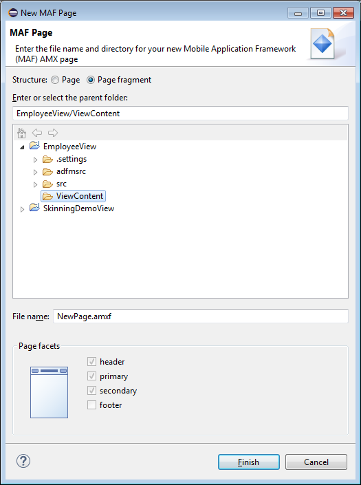
MAF AMX files are contained in the View project of the MAF application. You create these files using the New MAF Page dialog.
MAF offers two alternative ways of creating an MAF AMX page:
-
From the New menu (File > New > MAF Page)
-
By right-clicking the ViewContent folder of the View project and selecting New > MAF Page
To create an MAF AMX page, the MAF application must include a View project folder (see Chapter 2, "Getting Started with MAF Application Development"). Files created outside the ViewContent folder of the View project will not be included in the deployed application.
To create an MAF AMX page from the file menu:
-
From the top-level menu in OEPE, click File, and then select New > MAF Page.
-
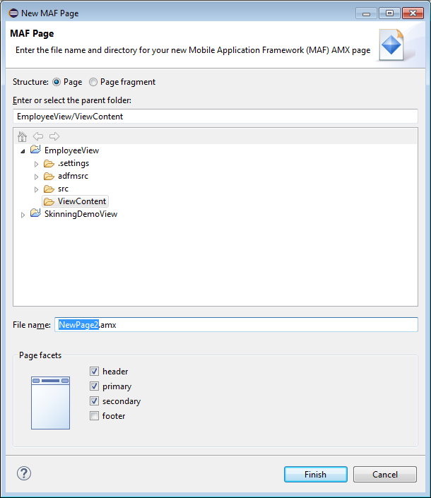
In the New MAF Page dialog, browse to the View folder for the MAF application for which you are creating the AMX page. (Note that you may have more than one View project in an application.)
-
Enter a name (or accept the default) and, if needed, a location for your new file.
-
Optionally, you may select which facets your new MAF AMX page will include as a part of the page layout:
-
Header
-
Primary
-
Secondary
-
Footer
For more information, see Section 12.3.1.3, "What Happens When You Create an MAF AMX Page" and Section 13.2.7, "How to Use a Facet Component."
Note that when you select or deselect a facet, the image representing the page changes dynamically to reflect the changing appearance of the page.
Note:
MAF retains your page facet selection and applies it to each subsequent invocation of the New MAF AMX Page dialog. -
-
Click Finish on the New MAF AMX Page dialog.
To create an MAF AMX page from a View component of the task flow:
-
Open a task flow file in the diagrammer (see Section 12.2.1, "How to Create a Task Flow" and Section 12.2.4, "What You May Need to Know About the MAF Task Flow Diagrammer")
-
Double-click a View component of the task flow to open the Create MAF AMX Page dialog that Figure 12-15 shows, and then enter a name and, if needed, a location for your new file. Click OK.
12.3.1.3 What Happens When You Create an MAF AMX Page
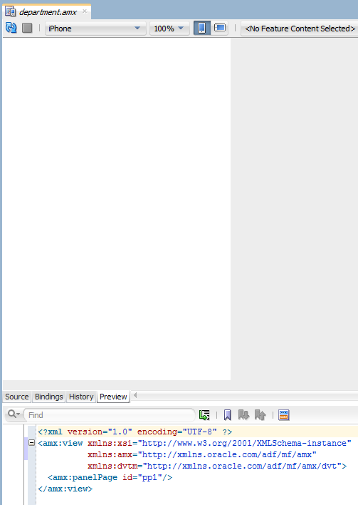
When you use the Create MAF AMX Page dialog to create an MAF AMX page, OEPE creates the physical file and adds it to the ViewContent directory of the View Controller project.
In the Project Explorer that Figure 12-16 shows, the ViewContent node contains a newly created MAF AMX file called department.amx.

OEPE also adds the code necessary to import the component libraries and display a page. This code is illustrated in the Source editor shown in Figure 12-16.
If you create a page with all the facets selected, note the following:
-
The header is created with an Output Text component because this component is typically used for the page title.
-
The primary and secondary actions are created with Button components because it is a typical pattern.
-
Since there is no single dominant pattern for the footer, it is created with an Output Text component by default because that component is used in some patterns and it prevents OEPE from generating the initial code with audit violation.
-
Adding either the primary or secondary action without adding the header facet still causes the header section to appear in the Page Facets section of Create MAF AMX Page dialog.
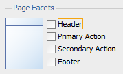
Figure 12-17 shows the Page Facet section of the Create MAF AMX Page dialog without any facets selected and Figure 12-18 shows the Preview pane with the generated MAF AMX code.
12.3.1.4 Using UI Editors
Note:
This feature is only available in the OEPE runtime and must be performed manually. It is not available as a design-time feature.12.3.1.5 Accessing the Page Definition File
MAF AMX supports OEPE's Go to Page Definition functionality that enables you to navigate to the MAF AMX page definition (see Figure 12-19 and Section 12.3.2.3.5, "What You May Need to Know About Generated Drag and Drop Artifacts") by using a context menu that allows you to locate and edit the binding information quickly.
You can invoke the context menu that contains the Go to Page Definition option from the following:
-
Source editor, as Figure 12-20 shows.
-
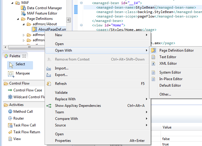
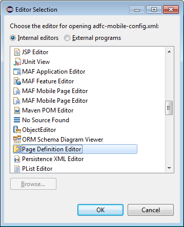
Application window, by right-clicking the page, selecting Open With > Other, and then selecting Page Definition Editor, as Figure 12-21 shows.
12.3.1.6 Sharing the Page Contents
You can enable sharing of contents of MAF AMX pages. Fragment (fragment) is a dynamic declarative component that allows for reusable parts of an MAF AMX page elements, including attributes and facets, to be inserted into the content represented by a template. This enables you to standardize the look and feel of your application by reusing the Fragment template across various pages within the application.
You can drag and drop an MAF AMX fragment file ( .amxf) onto an MAF AMX page or another fragment file to create a reference to the fragment and to define its attributes. The fragment file resides inside your project and you can drop it from the Project Explorer window into a target source file that is currently open in the Source editor.
Ensure that the MAF application includes a View project.
If the View project does not contain an MAF AMX page or MAF AMX page task flow from which to create a page, you can invoke the Create MAF AMX Page dialog by double-clicking a view icon in a task flow diagram (see Section 12.3.1.2, "Creating MAF AMX Pages").
To create a Fragment from the File menu:
-
From the top-level menu in OEPE, click File, and then select New > MAF Page.
-
In the New MAF Page dialog, click to select the Page Fragment button. Open the View Content node, enter a descriptive file name if you prefer, and then click Finish (see Figure 12-22). Note that the facets are not available for selection in a page fragment.
-
Upon completion of the dialog, a newly created file opens in the Source editor of OEPE (see Figure 12-23).
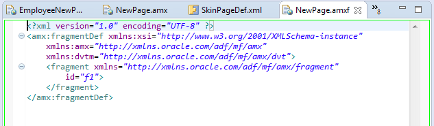
Example 12-11 shows an MAF AMX fragment file called fragment1.amxf.
Example 12-11 Fragment Definition
<amx:fragmentDef
   xmlns:xsi="http://www.w3.org/2001/XMLSchema-instance"
   xmlns:amx="http://xmlns.oracle.com/adf/mf/amx"
   xmlns:dvtm="http://xmlns.oracle.com/adf/mf/amx/dvt">
   <fragment xmlns="http://xmlns.oracle.com/adf/mf/amx/fragment" id="f1">
      <description id="d1">Description of the fragment</description>
      <facet id="f2">
         <description id="d4">Description of the facet</description>
         <facet-name id="f3">facet1</facet-name>
      </facet>
      <attribute id="a1">
         <description id="d2">Description of an attribute</description>
         <attribute-name id="a2">text</attribute-name>
         <attribute-type id="at1">String</attribute-type>
         <default-value id="d3">defaultValue</default-value>
      </attribute>
   </fragment>
   <amx:panelGroupLayout id="pgl1">
      <amx:facetRef facetName="facet1" id="fr1"/>
      <amx:outputText value="#{text}" id="ot1"/>
   </amx:panelGroupLayout>
</amx:fragmentDef>
To include the contents of the fragment in the MAF AMX page, you create a Fragment component (see Section 13.2.13, "How to Use the Fragment Component") and set its src attribute to the fragment file of your choice. Example 12-12 shows a fragment element added to an MAF AMX page. This element points to the fragment1.amxf as its page contents. At the same time, the facetRef element, which corresponds to the Facet Definition MAF AMX component, points to facet1 as its facet (MAF AMX Facet component). The facetRef element can only be specified in the .amxf file within the fragmentDef. You can pass attributes to the facetRef by specifying the MAF AMX attribute element as its child, which allows you to pass an EL variable from the Fragment to a Facet through the attribute's value.
Example 12-12 Fragment in MAF AMX Page
<?xml version="1.0" encoding="UTF-8" ?>
<amx:view xmlns:xsi="http://www.w3.org/2001/XMLSchema-instance"
          xmlns:amx="http://xmlns.oracle.com/adf/mf/amx"
          xmlns:dvtm="http://xmlns.oracle.com/adf/mf/amx/dvt">
   <amx:panelPage id="pp1">
      <amx:panelGroupLayout layout="vertical"
                            id="itemPgl"
                            styleClass="amx-style-groupbox">
         <amx:fragment id="f1"
                       src="/simpleFragment.amxf"
            <amx:attribute id="a1"
                           name="text"
                           value="defaultValue" />
            <amx:facet name="facet">
               <amx:outputText id="ot5" value="Fragment"/>
            </amx:facet>
         </amx:fragment>
      </amx:panelGroupLayout>
   </amx:panelPage>
</amx:view>
The Fragment supports the following:
-
Embedded popups (see Section 13.2.8, "How to Use a Popup Component").
-
Reusable user interface that can be placed on one or more other parent pages or fragments. This allows you to create a component that is composed of other components without bindings.
-
Definition of its own facets. This allows you to create a component such as a layout component that defines a header facet, summary facet, and detail facet, with each facet having its own style class as well as look and feel.
-
Data model with both attributes and collections.
MAF sample applications called FragmentDemo and CompGallery demonstrate how to create and use the fragments. These sample applications are available from File > New > MAF Examples.
12.3.2 How to Add UI Components and Data Controls to an MAF AMX Page
After you create an MAF AMX page, you can start adding MAF AMX UI components and data controls to your page.
12.3.2.1 Adding UI Components
You can use the Palette to drag and drop MAF AMX components and MAF AMX data visualization components onto the page. OEPE then adds the necessary declarative page code and sets certain values for component attributes.
The Palette displays MAF AMX components by categories:
-
Control Flow
-
Activities
For information on adding and using specific components, see Section 13.3, "Creating and Using UI Components."
The Palette also displays MAF AMX data visualization components by categories:
-
Common, with the following subcategories:
-
Chart
-
Gauge
-
Map
-
Miscellaneous
-
-
Shared Child Tags
-
Other Type-Specific Child Tags, with the following subcategories:
-
Chart
-
Gauge
-
NBox
-
Thematic Map
-
Timeline
-
Sunburst and Treemap
-
The MAF application must include a View project, which may or may not contain an MAF AMX page or MAF AMX page task flow from which to create a page.
As described in Section 12.3.1.2, "Creating MAF AMX Pages," you can invoke the Create MAF AMX Page dialog by double-clicking a view icon in a task flow diagram or by selecting New > MAF Page.
To add UI components to a page:
-
Open an MAF AMX page in the Source editor (default).
-
In the Tags panel of the Palette, select MAF AMX.
Tip:
If the Palette is not displayed (because it has been closed), choose Window > New Window from the main OEPE menu. This creates a new instance of OEPE that displays the Palette. By default, the Palette is displayed in the lower left-hand corner of OEPE. -
Select the component you wish to use, and then drag and drop it onto the Source editor or Structure window. You cannot drop components onto the Preview pane.
Note:
When building an MAF AMX page, you can only drop UI components into UI containers such as, for example, a Panel Group Layout.OEPE redraws the page in the Preview pane with the newly added component.
12.3.2.2 Using the Preview
Note:
This feature is only available in the OEPE runtime and must be performed manually. It is not available as a design-time feature.12.3.2.3 Adding Data Controls to the View
You can create databound UI components in an MAF AMX view by dragging data control elements from the Data Controls window and dropping them into either the Structure window or the Source editor. When you drag an item from the Data Controls window to either of these places, OEPE invokes a context menu of default UI components available for the item that you dropped. When you select the desired UI component, OEPE inserts it into an MAF AMX page. In addition, OEPE creates the binding information in the associated page definition file. If such file does not exist, then OEPE creates one. MAF provides a visual indicator for dropping data controls to inform you of the location of the new data control
Note:
A data control can only be dropped at a location allowed by the underlying XML schema.Depending on the approach you take, you can insert different types of data controls into the Structure window of an MAF AMX page. The data controls available from the Tags pane of the Palette are shown in Figure 12-24.
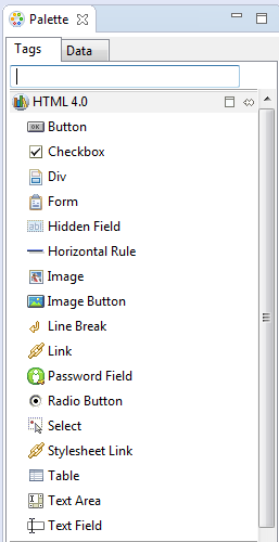
Dropping an attribute of a collection lets you create various input and output components. You can also create Button and Link components by dropping a data control operation on a page.
The respective action listener is added in the MAF AMX Button for each of these operations.
The data control attributes and operations can be dropped as one or more of the following MAF AMX UI components (see Section 13.3, "Creating and Using UI Components"):
-
Button
-
Link
-
Input Date
-
Input Date with Label
-
Input Text
-
Input Text with Label
-
Output Text
-
Output Text with Label
-
Iterator
-
List Item
-
List View
-
Select Boolean Checkbox
-
Select Boolean Switch
-
Select One Button
-
Select One Choice
-
Select One Radio
-
Select Many Checkbox
-
Select Many Choice
-
Convert Date Time
-
Convert Number
-
Form
-
Read Only Form
-
Parameter Form
The following Date and Number types are supported:
-
java.util.Date -
java.sql.Timestamp -
java.sql.Date -
java.sql.Time -
java.lang.Number -
java.lang.Integer -
java.lang.Long -
java.lang.Float -
java.lang.Double
For information on how to use the Data Controls window in OEPE, see Section 14.6, "Creating Databound UI Components from the Data Controls Palette."
12.3.2.3.1 Dragging and Dropping Attributes
If your MAF AMX page already contains a Panel Form Layout component or does not require to have all the fields added, you can drop individual attributes from a data control. Depending on the attributes types, different data binding menu options are provided as follows:
This category provides options for creating MAF Input Date and MAF Input Date with Label controls. Figure 12-25 shows the context menu for adding date controls that appears when you drag an attribute from the Data Controls window onto the Source editor or Structure window of an MAF AMX page.
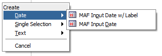
This category provides options for creating the following controls:
-
MAF Select One Button
-
MAF Select One Choice
-
MAF Select One Radio
-
MAF Select Boolean Checkbox
-
MAF Select Boolean Switch
If you are working with an existing MAF AMX page and you select MAF Select One Button or MAF Select One Choice option, an appropriate version of the Edit List Binding dialog is displayed (see Figure 12-26). If you drop a control onto a completely new MAF AMX page, the Edit Action Binding dialog opens instead. After you click OK, the Edit List Binding dialog opens.
Note:
The Edit List Binding or Edit Boolean Binding dialog appears every time you drop any data control attributes as any of the single selection or boolean selection components, respectively.
If you select MAF Select One Radio option, another version of the Edit List Binding dialog is displayed, as shown in Figure 12-27.
If you select MAF Select Boolean Checkbox or MAF Select Boolean Switch option, another version of the Edit List Binding dialog is displayed, as shown in Figure 12-28.
This category provides options for creating the following controls:
-
MAF Input Text
-
MAF Input Text with Label
-
MAF Output Text
-
MAF Output Text with Label
Figure 12-29 shows the context menu for adding text controls that appears when you drag an attribute from the Data Controls window onto the Source editor or Structure window of an MAF AMX page.
12.3.2.3.2 Dragging and Dropping Operations
In addition to attributes, you can drag and drop operations and custom methods. Depending on the type of operation or method, different data binding menu options are provided, as follows:
This category is for data control operations. It provides the following options (see Figure 12-30):
-
MAF Button
-
MAF Link
-
MAF Parameter Form
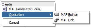
Note:
If you drop an operation or a method as a child of the List View control, the context menu does not appear and the List Item is created automatically because no other valid control can be dropped as a direct child of the List View control. OEPE creates a binding similar to the following for the generated List Item:
<amx:listItem actionListener="#{bindings.getLocation.execute}"/>
This category is for custom methods. It provides the following options (see Figure 12-31):
-
MAF Button
-
MAF Link
-
MAF Parameter Form
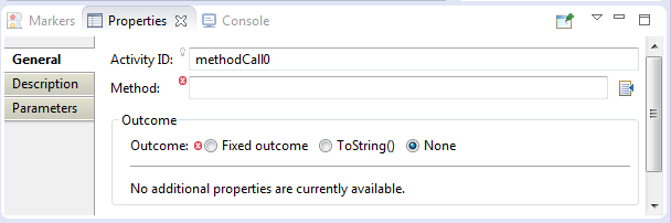
The MAF Parameter Form option allows you to choose the method or operation arguments to be inserted in the form, as well as the respective controls for each of the arguments (see Figure 12-32).
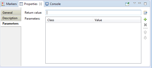
The following data bindings are generated after you select the appropriate options in the Edit Form Fields dialog:
<amx:panelFormLayout id="pfl1">
   <amx:inputText id="it1"
                  value="#{bindings.empId.inputValue}"
                  label="#{bindings.empId.hints.label}" />
</amx:panelFormLayout>
<amx:commandButton id="cb1"
                   actionListener="#{bindings.ExecuteWithParams1.execute}"
                   text="ExecuteWithParams1"
                   disabled="#{!bindings.ExecuteWithParams1.enabled}"/>
For more information about generated bindings, see Section 12.3.2.3.4, "What You May Need to Know About Generated Bindings."
The following are supported control types for the MAF Parameter Form:
-
MAF Input Date
-
MAF Input Date with Label
-
MAF Input Text
-
MAF Input Text with Label
-
MAF Output Text with Label
12.3.2.3.3 Dragging and Dropping Collections
You can drag and drop collections. Depending on the type of collection, different data binding menu options are provided, as follows:
This category provides options for creating multiple selection controls. The following controls can be created under this category (see Figure 12-33):
-
MAF Select Many Checkbox
-
MAF Select Many Choice
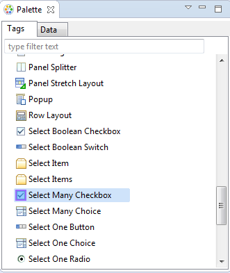
If you select either Select Many Choice or Select Many Checkbox as the type of the control you want to create, the Edit List Binding dialog is displayed (see Figure 12-34).
This category is used to create the MAF AMX Panel Form controls. When you select Form from the HTML pane of the Palette, OEPE displays the New Form dialog (see Figure 12-35):
Select the method (get or post) and enter the desired action. OEPE adds a basic HTML form tag to the source; you can edit the Value fields from the Properties pane (see Figure 12-36).
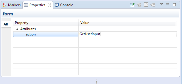
This provides an option for creating the MAF AMX Iterator with child components (see Figure 12-37).
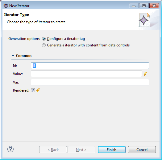
If you select Generate an Iterator with content from data controls, OEPE displays a Browse link from which you can select the file that contains the content.
The following data bindings are generated after you select the appropriate options in the Edit Iterator dialog:
<amx:iterator id="i1"
              var="row"
              value="#{bindings.jobs.collectionModel}">
   <amx:panelLabelAndMessage id="plam6"
                             label="#{bindings.jobs.hints.jobId.label}">
      <amx:outputText id="ot6" value="#{row.jobId}" />
   </amx:panelLabelAndMessage>
   <amx:panelLabelAndMessage id="plam5"
                             label="#{bindings.jobs.hints.title.label}">
      <amx:outputText id="ot5" value="#{row.title}" />
   </amx:panelLabelAndMessage>
   <amx:inputText id="it1"
                  value="#{row.bindings.minSalary.inputValue}"
                  label="#{bindings.jobs.hints.minSalary.label}" />
   <amx:inputText id="it2"
                  value="#{row.bindings.maxSalary.inputValue}"
                  label="#{bindings.jobs.hints.maxSalary.label}" />
</amx:iterator>
For more information about generated bindings, see Section 12.3.2.3.4, "What You May Need to Know About Generated Bindings."
The following are supported controls for MAF Iterator:
-
MAF Input Text
-
MAF Input Text with Label
-
MAF Output Text
-
MAF Output Text with Label
This provides an option for creating the MAF AMX List View with child components (see Figure 12-38).
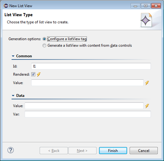
Table 12-4 lists the supported List Formats that are displayed in the ListView Gallery.
12.3.2.3.4 What You May Need to Know About Generated Bindings
Table 12-5 shows sample bindings that are added to an MAF AMX page when components are dropped.
Table 12-5 Sample Data Bindings
| Component | Data Bindings |
|---|---|
|
Button |
<amx:commandButton id="commandButton1"
                   actionListener="#{bindings.FindContacts.execute}"
                   text="FindContacts"
                   disabled="#{!bindings.FindContacts.enabled}">
</amx:commandButton>
|
|
Link |
<amx:commandLink id="commandLink1"
                 actionListener="#{bindings.FindContacts.execute}"
                 text="FindContacts"
                 disabled="#{!bindings.FindContacts.enabled}">
</amx:commandLink>
|
|
Input Date with Label |
<amx:inputDate id="inputDate1"
               value="#{bindings.timeStamp.inputValue}"
               label="#{bindings.timeStamp.hints.label}">
</amx:inputDate>
|
|
Input Date |
<amx:inputDate id="inputDate1"
               value="#{bindings.timeStamp.inputValue}">
</amx:inputDate>
|
|
Input Text with Label |
<amx:inputText id="inputText1"
               value="#{bindings.contactData.inputValue}"
               label="#{bindings.contactData.hints.label}">
</amx:inputText>
|
|
Input Text |
<amx:inputText id="inputText1"
               value="#{bindings.contactData.inputValue}"
               simple="true">
</amx:inputText>
|
|
Output Text |
<amx:outputText id="outputText1"
               value="#{bindings.contactData.inputValue}">
</amx:outputText>
|
|
Output Text with Label |
<amx:panelLabelAndMessage id="panelLabelAndMessage1"
          label="#{bindings.contactData.hints.label}">
   <amx:outputText id="outputText1"
                   value="#{bindings.contactData.inputValue}"/>
</amx:panelLabelAndMessage>
|
|
Select Boolean Checkbox |
<amx:selectBooleanCheckbox id="selectBooleanCheckbox1"
           value="#{bindings.contactData.inputValue}"
           label="#{bindings.contactData.label}">
</amx:selectBooleanCheckbox>
|
|
Select Boolean Switch |
<amx:selectBooleanSwitch id="selectBooleanSwitch"
           value="#{bindings.contactData.inputValue}"
           label="#{bindings.contactData.label}">
</amx:selectBooleanSwitch>
|
|
Select One Button |
<amx:selectOneButton id="selectOneButton1"
           value="#{bindings.contactData.inputValue}"
           label="#{bindings.contactData.label}"
           required="#{bindings.contactData.hints.mandatory}">
   <amx:selectItems value="#{bindings.contactData.items}"/>
</amx:selectOneButton>
|
|
Select One Choice |
<amx:selectOneChoice id="selectOneChoice1"
                value="#{bindings.contactData.inputValue}"
                label="#{bindings.contactData.label}">
   <amx:selectItems id="selectItems1"
                    value="#{bindings.contactData.items}"/>
</amx:selectOneChoice>
|
|
Select Many Checkbox |
<amx:selectManyCheckbox id="selectManyCheckbox1"
                      value="#{bindings.AssetView.inputValue}"
                      label="#{bindings.AssetView.label}">
   <amx:selectItems id="selectItems1"
                    value="#{bindings.AssetView.items}"/>
</amx:selectManyCheckbox>
|
|
Select One Radio |
<amx:selectOneRadio id="selectOneRadio1"
               value="#{bindings.contactData.inputValue}"
               label="#{bindings.contactData.label}"
   <amx:selectItems id="selectItems1"
                    value="#{bindings.contactData.items}"/>
</amx:selectOneRadio>
|
|
Select Many Choice |
<amx:selectManyChoice id="selectManyChoice1"
                      value="#{bindings.AssetView.inputValue}"
                      label="#{bindings.AssetView.label}">
   <amx:selectItems id="selectItems1"
                    value="#{bindings.AssetView.items}"/>
</amx:selectManyChoice>
|
12.3.2.3.5 What You May Need to Know About Generated Drag and Drop Artifacts
The first drag and drop event generates the following directories and files:
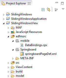
Figure 12-39 shows a sample DataBindings.cpx file generated upon drag and drop.
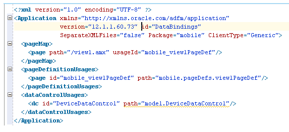
The DataBindings.cpx files define the binding context for the entire MAF AMX application feature and provide the metadata from which the binding objects are created at runtime. An MAF AMX application feature may have more than one DataBindings.cpx file if a component was created outside of the project and then imported. These files map individual MAF AMX pages to page definition files and declare which data controls are being used by the MAF AMX application feature. At runtime, only the data controls listed in the DataBindings.cpx files are available to the current MAF AMX application feature.
OEPE automatically creates a DataBindings.cpx file in the default package of the ViewController project when you for the first time use the Data Controls window to add a component to a page or an operation to an activity. Once the DataBindings.cpx file is created, OEPE adds an entry for the first page or task flow activity. Each subsequent time you use the Data Controls window, OEPE adds an entry to the DataBindings.cpx for that page or activity, if one does not already exist.
Once OEPE creates a DataBindings.cpx file, you can open it in the Source view (see Figure 12-39) or the editor.
The Page Mappings (pageMap) section of the file maps each MAF AMX page or task flow activity to its corresponding page definition file using an ID. The Page Definition Usages (pageDefinitionUsages) section maps the page definition ID to the absolute path for page definition file in the MAF AMX application feature. The Data Control Usages (dataControlUsages) section identifies the data controls being used by the binding objects defined in the page definition files. These mappings allow the binding container to be initialized when the page is invoked.
You can use the editor to change the ID name for page definition files or data controls by double-clicking the current ID name and editing inline. Doing so will update all references in the MAF AMX application feature. Note, however, that OEPE updates only the ID name and not the file name. Ensure that you do not change a data control name to a reserved word.
You can also click the DataBindings.cpx file's element in the Structure window and then use the Properties window to change property values.
Figure 12-40 shows a sample PageDef file generated upon drag and drop.
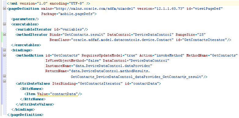
Page definition files define the binding objects that populate the data in MAF AMX UI components at runtime. For every MAF AMX page that has bindings, there must be a corresponding page definition file that defines the binding objects used by that page. Page definition files provide design-time access to all the bindings. At runtime, the binding objects defined by a page definition file are instantiated in a binding container, which is the runtime instance of the page definition file.
The first time you use the Data Controls window to add a component to a page, OEPE automatically creates a page definition file for that page and adds definitions for each binding object referenced by the component. For each subsequent databound component you add to the page, OEPE automatically adds the necessary binding object definitions to the page definition file.
By default, the page definition files are located in the mobile.PageDefs package in the Application Sources node of the ViewController project. If the corresponding MAF AMX page is saved to a directory other than the default, or to a subdirectory of the default, then the page definition is also be saved to a package of the same name.
For information on how to open a page definition file, see Section 12.3.1.5, "Accessing the Page Definition File." When you open a page definition file in the editor, you can view and configure bindings, contextual events, and parameters for an MAF AMX page using the following tabs:
-
Bindings and Executables: this tab shows three different types of objects: bindings, executables, and the associated data controls. Note that data controls do not display unless you select a binding or executable.
By default, the model binding objects are named after the data control object that was used to create them. If a data control object is used more than once on a page, OEPE adds a number to the default binding object names to keep them unique.
-
Contextual Events: you can create contextual events to which artifacts in an MAF AMX application feature can subscribe.
-
Parameters: parameter binding objects declare the parameters that the page evaluates at the beginning of a request. You can define the value of a parameter in the page definition file using static values or EL expressions that assign a static value.
When you click an item in the editor (or the associated node in the Structure window), you can use the Properties window to view and edit the attribute values for the item, or you can edit the XML source directly by clicking the Source tab.
12.3.2.3.6 Using the MAF AMX Editor Bindings Tab
OEPE's Bindings tab (see Figure 12-41) is available in the MAF AMX Editor. It displays the data bindings defined for a specific MAF AMX page. If you select a binding, its relationship to the underlying Data Control are shown and the link to the PageDef file is provided.
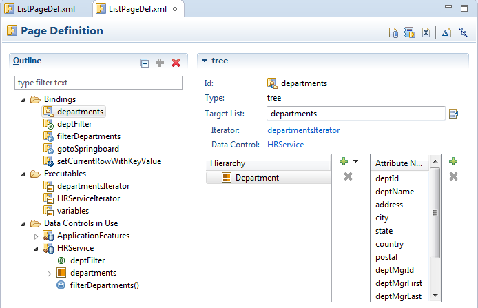
12.3.2.3.7 What You May Need to Know About Removal of Unused Bindings
When you delete or cut an MAF AMX component from the Structure window, unused bindings are automatically removed from your page.
Note:
Deleting a component from the Source editor does not trigger the removal of bindings.Figure 12-42 demonstrates the deletion of a List View component that references bindings. Upon deletion, the related binding entry is automatically removed from the corresponding PageDef.xml file.
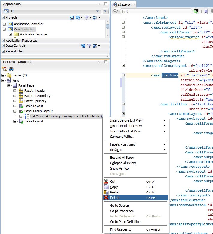
Figure 12-43 demonstrates the removal of the List View component by cutting it from the page.
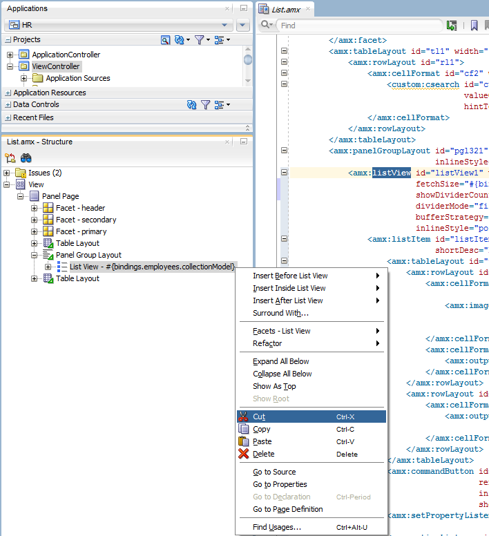
After clicking Cut, you are presented with the Confirm Removal of Bindings dialog that prompts you to choose whether or not to delete the corresponding bindings, as shown in Figure 12-44.
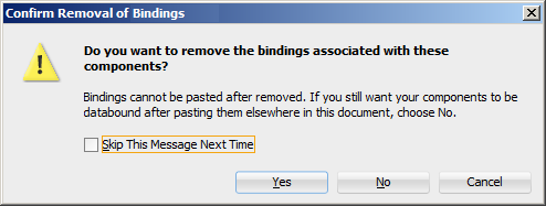
12.3.2.4 What You May Need to Know About Element Identifiers and Their Audit
MAF generates a unique element identifier (id) and automatically inserts it into the MAF AMX page when an element is added by dropping a component from the Palette, or by dragging and dropping a data control. This results in a valid identifier in the MAF AMX page that differentiates each component from others, possibly similar components within the same page.
MAF provides an identifier audit utility that does the following:
-
Checks the presence and uniqueness of identifiers in an MAF AMX page.
-
If the identifier is not present or not unique, an error is reported for each required
idattribute of an element. -
Provides an automatic fix to generate a unique
idfor the element when a problem with the identifier is reported.
Figure 12-45 and Figure 12-46 show the identifier error reporting in the Source editor and Structure pane respectively.
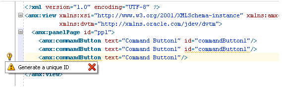
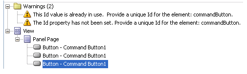
In addition to the id, the audit utility checks the popupId and alignId attributes of the Show Popup Behavior operation (see Section 13.2.8, "How to Use a Popup Component").
Figure 12-47 and Figure 12-48 show the Show Popup Behavior's Popup Id and Align Id attributes error reporting in the Source Editor respectively.
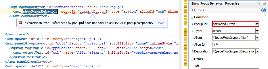
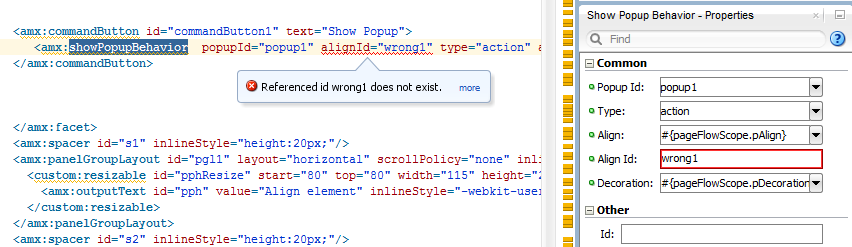
12.3.3 What You May Need to Know About the Server Communication
The security architecture used by MAF guarantees that the browser hosting an MAF AMX page does not have access to the security information needed to make connections to a secure server to obtain its resources. This has a direct impact on AJAX calls made from MAF AMX pages: these calls are not supported, which poses limitations on the use of Java Script from within MAF AMX UI components. Communication with the server must occur from the embedded Java code layer.