CREATE PROPERTY GRAPH
Purpose
You can create property graphs from views on simple and multiple tables, hybrid partitioned tables, database links, object tables, table functions and polymorphic table functions. Views can project aggregates, window functions, pseudocolumns as well as virtual columns. Synonyms for views and nested views are also supported.
Prerequistes
You need the CREATE PROPERTY GRAPH privilege to create a property graph in your own schema. To create a property graph in any schema except SYS and AUDSYS, you must have the CREATE ANY PROPERTY GRAPH privilege.
Syntax

Description of the illustration create_property_graph.gif
(edge_tables_clause::= , graph_options)
vertex_tables_clause::=

Description of the illustration vertex_tables_clause.gif
vertex_table_definition::=

Description of the illustration vertex_tables_definition.gif
graph_table_level_and_properties
graph_element_name_and_key::=

Description of the illustration graph_element_name_and_key.gif
graph_element_object_name::=
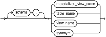
Description of the illustration graph_element_object_name.gif
graph_element_key::=

Description of the illustration graph_element_key.gif
graph_table_label_and_properties::=

Description of the illustration graph_table_label_and_properties.gif
graph_table_label_properties_clause::=

Description of the illustration graph_table_label_properties_clause.gif
graph_table_properties_alternatives::=

Description of the illustration graph_table_properties_alternatives.gif
column_name_list::=
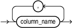
Description of the illustration column_name_list.gif
column_or_expression::=
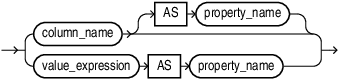
Description of the illustration column_or_expression.gif
graph_table_label_clause::=

Description of the illustration graph_table_label_clause.gif
edge_tables_clause::=

Description of the illustration edge_tables_clause.gif
edge_tables_definition::=
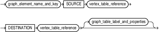
Description of the illustration edge_tables_definition.gif
graph_table_level_and_properties
vertex_table_reference::=

Description of the illustration vertex_table_reference.gif
graph_options::=
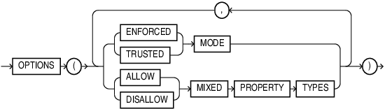
Description of the illustration graph_options.gif
Semantics
IF NOT EXISTS
Specifying IF NOT EXISTS has the following effects:
-
If the property graph does not exist, a new property graph is created at the end of the statement.
-
If the property graph exists, the existing property graph is what you have at the end of the statement. A new one is not created because the older one is detected.
Using IF EXISTS with CREATE results in the following error: Incorrect IF NOT EXISTS clause for CREATE statement .
You must create a property graph with the vertex_tables_clause .
Specify the schema to contain the property graph. If you omit schema, then Oracle Database creates the graph in your own schema.
The name of the property graph must not be used by any other object in the same schema, because property graphs share the name space used for tables and views. ORA-00955 is raised in the case of name conflicts.
Specify OR REPLACE to re-create the property graph, if it already exists. You can use this clause to change the definition of an existing property graph without dropping, re-creating, and regranting object privileges previously granted on it.
If any materialized views are dependent on the property graph, then those materialized views will be marked UNUSABLE and will require a full refresh to restore them to a usable state. Invalid materialized views cannot be used by query rewrite and cannot be refreshed until they are recompiled.
vertex_tables_clause
The vertex_tables_clause lets you define one or more vertex tables for the property graph. A vertex_table_definition needs to specify the underlying object name. It can optionally specify more items (like labels and properties) as explained below.
You can define a property graph by specifying just the name of the underlying object used to define the graph element table. In this case a default label with the same name as the underlying table is created and all the columns are exposed as graph properties.
The object name can be the name of a table, an external table, a materialized view, or a synonym of a table or materialized view.
The object name can be qualified by specifying the schema it resides in. This means that you can use objects from other schemas to define a graph element table. If no option is specified, the name of the specified object is used as the name of the graph element table.
Example: Create a Property Graph with Vertex Table
In the following example, the vertex table name my_table_1 is the name of underlying object my_table_1:
CREATE PROPERTY GRAPH "myGraph" VERTEX TABLES (my_table_1);Example: Create a Property Graph with a Schema-Qualified Vertex Table
In the following example, the name my_table_1 is qualified by the schema other_schema and the vertex table name is the name of underlying object my_table_1:
CREATE PROPERTY GRAPH "myGraph" VERTEX TABLES (other_schema.my_table_1);graph_element_name_and_key
The graph_element_name_and_key clause lets you specify:
-
The name of the schema object to be used for defining a graph element table. The name of the graph element table defaults to the graph_element_object_name without the schema qualification, if an
ASclause is not used to provide an alternative name. -
One or more column names used to explicitly specify the columns of the underlying object that are used to identify a row in that underlying object.
Graph element table names are defined in a name space specific to the property graph: they do not conflict with the names of schema objects, or with the names of graph element tables defined in other property graphs. This means that an edge table cannot use the name of a vertex table.
Graph element table names follow the same rules as other identifiers: they may be quoted to indicate case-sensitivity, and are limited by default to 128 characters. Any subsequent symbolic references to a graph element table in the DDL statement must use the graph element table name, not the name of its underlying object. In particular, you must use the graph element table name when you define the source and destination vertex table of an edge table.
graph_element_object_name identifies the table, view, or materialized view directly, or indirectly using a synonym for the table, view, or materialized view.
You can omit the clause graph_element_key in the following cases:
-
The clause graph_element_object_name identifies a base table with a single primary key constraint. The primary key constraint takes precedence over any unique key that might also be defined.
-
The clause graph_element_object_name identifies a base table without primary keys and a single unique key constraint where all columns are not nullable.
You must specify graph_element_key if graph_element_object_name identifies a view or materialized view.
Example
The example shows the ways graph_element_key is used. In vertex table VT3 it is used to specify a composite key made of multiple columns of the underlying table. Vertex table ALTVT2 is defined from the same underlying object used to define vertex table VT2, but a different column of that object (PK4) is specified as identifier for its vertices. It is assumed that vertex table VT1 has a primary key constraint or unique key with not null columns.
CREATE PROPERTY GRAPH "myGraph"
     VERTEX TABLES (
       VT1,
       VT2 KEY(PK2),
       VT3 KEY(PK31, PK32),
       VT2 AS ALTVT2 KEY(PK4)
     );
Note that a same underlying object VT2 can be used to define another graph element table using the same primary key used to define other graph element tables from VT2. So in the example above, specifying PK2 instead of PK4 for ALTVT2 is allowed.
When the graph_element_key clause is present, all the declared column names must match column names of the underlying object of the graph element table.
When the graph_element_key clause is omitted, the database will infer the columns from the constraints of the underlying object. If multiple primary or unique key constraints are defined for that object, inferring a key fails and an error is raised. Note that the primary constraint is only used to infer the key for the graph element table, no dependency to the constraint is created as a result of this inference. This means that the constraint may be dropped later without invalidating the graph or impact to its definition.
You can change this behavior and create a dependency to the constraint with the ENFORCED MODE option.
You can define multiple graph element tables from the same object. For example, a table may act as a different edge table in the same graph. You can also define a graph from tables from different schemas but with the same name. In both cases you must take care to avoid name collisions by specifying an alternative graph element table name with the optional AS clause.
Example: Create a Property Graph with the AS Clause
CREATE PROPERTY GRAPH "myGraph" VERTEX TABLES (my_table_1, other_schema.my_table_1 AS my_table2);Restrictions
Restrictions that apply on primary key constraints also apply on vertex and edge table keys:
-
Columns of the following built-in data types can be used to define keys of vertex or edge tables:
VARCHAR2,NVARCHAR2,NUMBER,BINARY_FLOAT,BINARY_DOUBLE,CHAR,NCHAR,DATE,INTERVAL(bothYEAR TO MONTHandDAY TO SECOND), andTIMESTAMP(but notTIMESTAMP WITH TIME ZONE). -
A composite key cannot exceed 32 columns.
edge_tables_clause
Use edge_tables_clause to specify one or more edge_table_definition clauses. Each edge_table_definition clause specifies the underlying object used to define the edge table of the graph.
edge_table_definition
Use edge_table_definition to explicitly define the vertex table that acts as the source of the edge, and the vertex table that acts as the destination of the edge using the keywords SOURCE and DESTINATION.
vertex_table_reference
The source and destination of the edge specify a vertex_table_reference. The vertex_table_reference specifies three components:
-
The graph element name of a vertex table, graph_element_name
-
A list of columns of the edge table to be treated as foreign key graph_element_key.
-
A list of columns of the referenced vertex table to be treated as referenced keys column_name_list
The graph_element_name of a vertex_table_reference clause must be defined by a preceding vertex_tables_definition clause. A vertex table name defined in the vertex_tables_definition may be used to define multiple edge table definitions, either as a source for the edge, a destination, or both.
Example
Given the following vertex tables defined as follows:
CREATE PROPERTY GRAPH "myGraph"
     VERTEX TABLES (
       VT1,
       VT2 KEY(PK2),
       VT3 KEY(PK31, PK32),
       VT2 AS ALTVT2 KEY(PK4)
     )
     EDGE TABLES (
       E1 SOURCE VT1
          DESTINATION VT2,
       E2 SOURCE      KEY(FK1) REFERENCES VT1 (PK1)
          DESTINATION KEY(FK2) REFERENCES VT2 (PK2),
       E3 SOURCE      KEY(FK1) REFERENCES VT1 (PK1)
          DESTINATION VT2,
       E4 SOURCE VT1
          DESTINATION KEY(FK5) REFERENCES VT2(RK5))
;
Both vertex-table-reference from edge table E1 to, respectively, source table VT1 and destination table VT2 are declared implicitly. When using this syntax, the user relies on the database to infer source and destination keys from existing foreign-key constraints between E1 and, respectively, VT1 and VT2. In this case, there must be exactly only foreign-key constraints between E1 and VT1 (respectively, VT2).
If that is not the case an error is raised. Note that the foreign key constraint is only used to infer the foreign key relationships between an edge table and its source and destination vertex tables. No dependency to the foreign key constraint is created as a result of this inference. This means that the constraint may be dropped later without invalidating the graph or impact to its definition.
In contrast, both vertex-table-references from edge table E2, respectively, source vertex table VT1 and destination vertex table VT2 are declared explicitly. This syntax is mandatory when there are no or multiple foreign constraints defined between E2 and its referenced vertex tables.
Implicit and explicit syntax can be mixed, as shown for edge table E3 and E4, wherein the former uses an explicit syntax only of the source table, while the latter uses it only for the destination table.
Note that the column_name_list clause that specifies the columns of the underlyng object for the referenced vertex table to be treated as referenced key don’t necessarily match the columns specified in the graph-element-key sub-clause of the vertex-definition clause that defined the referenced vertex table. This is illustrated with edge table E4 from the example above: the referenced key specified for VT2 is RK5, whereas the key that was specified in the vertex table definition clause for VT2 was PK2.
graph_table_label_and_properties
Use graph_table_label_and_properties to specify the labels and properties of a graph. Then you can formulate graph queries using the labels of a graph and the properties defined by these labels.
Graph Labels and Properties
You can associate graph element tables with labels that expose the columns of the underlying object as properties. A label has a name and declares a mapping of property names to columns of the underlying object for a given graph element table. Labels give you a way to refer to one or more graph element tables in a graph query using a same label name. Properties give you a way to refer to columns of one or more graph element tables using a same, possibly label qualified, property name.
You can associate one label to multiple graph element tables, provided that all the graph element tables that share this label declare the same property name. The columns or value expressions exposed by the same property name must have union compatible types.
A graph element table may be associated with multiple labels.
Graph element tables are always associated with at least one label. If none is defined explicitly, a label is assigned automatically with the same name as the graph element table.
Declaring labels and properties is optional. All the following ways to explicitly declare properties and labels are valid:
-
Only properties using graph_table_label_properties_clause
-
Only labels using graph_table_label_clause
-
Both properties and labels using graph_table_label_properties_clause
-
No properties or labels
graph_table_label_properties_clause
The properties are derived from columns or SQL value expressions of columns of the underlying object used to define the graph element table. By default, all visible columns are mapped to properties and the names of the properties default to the names of these columns. Pseudo-columns cannot be exposed as a property.
The graph_table_label_properties_clause provides the following options:
-
PROPERTIES [ ARE ] ALL COLUMNSAll visible columns of the graph element table are exposed as properties of the label with the same names as the column names. (This is the default when no properties are specified.) Note that all visible columns that are used as keys will also be exposed as properties.
-
PROPERTIES [ ARE ] ALL COLUMNS EXCEPT(column_name_list)All visible columns are exposed as properties of the label except for the ones explicitly listed. This option is useful, if the number of columns not supposed to be exposed as properties is small compared to the number of columns exposed as properties.
-
PROPERTIES(column_name_list)Only the columns explicitly listed become properties of the label with the same names as the column names. This option is useful, if the number of columns exposed as properties is small compared to the number of columns not supposed to be exposed as properties, or if the user wants to expose invisible columns. It is also useful when renaming some or all of the properties is necessary, as shown in the following:
-
PROPERTIES(column_name_list AS property_name )Only the columns explicitly listed become properties of the label. If
ASproperty_name is appended to the column_name, then the property_name is used as the property name, otherwise the property name defaults to the column name. A property name can only be defined once per label. TheASclause is useful to enable association of one label to multiple graph element tables. -
PROPERTIES(value_expression AS property_name, ...)It is possible to define a property as an expression over columns of the underlying object used to define a graph element table. The
ASclause is mandatory in this case. A value expression can be a scalar expression, or a function expression, or expression list. It can contain only the following forms of expression:-
Columns of the underlying object
-
Constants: strings or numbers
-
Deterministic functions — either SQL built-in functions or PL/SQL functions
No other expression forms are valid (in particular, sub-query expressions and aggregate functions are invalid). The expression can only return a scalar data type. SQL operator used in the expression must be deterministic
-
-
NO PROPERTIESThe label does not expose any column of the underlying object associated with the graph element table.
Note that that for a given vertex or edge table, the properties exposed in the various labels applied to this vertex or edge table must have the same definition.
graph_table_properties_alternatives
You can control explicitly what columns are exposed as properties using the options of graph_table_properties_alternatives clause.
Note that for implicit clauses, for example ALL COLUMNS, the list of exposed columns is determined when the graph is created. If you add additional columns to a table after you create the graph, for example you add a virtual column, the graph will not reflect the virtual column.
Examples
The following example illustrates various uses of graph_table_label_and_properties for declaring labels associated to graph element tables (here only vertex tables) and their properties:
CREATE PROPERTY GRAPH "myGraph"
  VERTEX TABLES (
    HR.VT1,
    VT1  AS ALTVT1,
    VT2  LABEL "foo" ,
    VT3  NO PROPERTIES,
    VT4  PROPERTIES(C1),
    VT5  PROPERTIES(C1, C2 as P2),
    VT6  LABEL "bar" LABEL "weighted" NO PROPERTIES,
    VT7  LABEL "bar2" PROPERTIES ARE ALL COLUMNS EXCEPT (C3),
    VT8  LABEL "weighted" NO PROPERTIES DEFAULT LABEL,
    VT9  PROPERTIES(Cx + Cy * 0.15 AS PX, Cz AS PZ),
    VT10 PROPERTIES(JSON_VALUE(JCOL,
      '$.person.creditScore[0]' returning number) AS CREDITSCORE,
    VT11 PROPERTIES(XMLCAST(XMLQUERY('/purchaseOrder/poDate'
       PASSING XCOL RETURNING CONTENT) AS DATE) AS PURCHASEDATE
 );
The meaning of each vertex table definition of the example:
-
Vertex table
VT1defines (implicitly) a single labelVT1that exposes all the visible columns of the underlying objectHR.VT1. This is the default when no options to specify label or property are used. -
Vertex table
ALTVT1defines (implicitly) a single labelALTVT1that exposes all the visible columns of the underlying objectVT1. If object nameVT1resolves toHR.VT1, both vertex tablesALTVT1andVT1exposes the same columns from the same underlying objectHR.VT1 -
Vertex table
VT2defines a single labelfoothat exposes all the visible columns of the underlying objectVT2. -
Vertex table
VT3defines (implicitly) a single labelVT3without any properties. No columns from the underlying objectVT3are exposed. -
Vertex table
VT4defines (implicitly) a single labelVT4with a single propertyC1that exposes the columnC1of the underlying objectVT4. -
Vertex table
VT5defines (implicitly) a single labelVT5with a two propertiesC1andP2, that exposes, respectively, columnC1andC2of the underlying objectVT5. -
Vertex table
VT6defines two labels,barandweighted, such that labelbarexposes all visible columns of underlying objectVT6as properties, while label “weighted” has no properties. -
Vertex table
VT7defines a single labelbarthat exposes all columns of the underlying objectVT3but its columnC3. -
Vertex table
VT8defines two labels,bar2andVT8(via theDEFAULT LABEL). The former has no properties while the later exposes all columns as properties. -
Vertex table
VT9defines (implicitly) a single labelVT9with two propertiesPXandPZ, withPXexposing an expression over columnsCxandCyof the underlying objectVT9, whilePZexposes its columnCz. -
Vertex table
VT10defines one propertyCREDITSCOREthat extracts creditScore value as number data type from theJSONtype columnJCOL. -
Vertex table
VT11defines one propertyPURCHASEDATEthat extracts purchase order date value as date data type from theXMLtypecolumnXCOL.
graph_options
Use the OPTIONS clause to specify a comma separated list of options. Each option can appear only once. You can specify the mode of the graph, one of ENFORCED or TRUSTED. You can either allow or disallow mixed types in properties with the same name.
ENFORCED or TRUSTED Mode
Option ENFORCED on the property graph means that guarantees are enforced over the entire graph via constraints in the ENABLE VALIDATE state.
If you do not specify ENFORCED , the mode is TRUSTED. This is the default mode.
A property graph is in ENFORCED mode if :
-
All of its graph element tables are defined with a primary key that matches an existing
ENABLE VALIDATEprimary key constraint, or a unique key constraint in theENABLE VALIDATEstate where all columns are not nullable. -
All vertex table references from edge tables are defined with a foreign key that matches an existing
ENABLE VALIDATEforeign key constraint between the underlying objects for the edge and the vertex table respectively, that (foreign key constraint) defines the source or destination vertex table reference. Further, the foreign key columns must have aNOT NULLconstraint, and aENABLE VALIDATEprimary key constraint, or both a unique and not null constraints, must be defined on the referenced keys for each of the source and destination table.
If neither one of these conditions is true, then the property graph is in TRUSTED mode. This is the default mode.
Example: Creation of a Property Graph in Enforced Mode
CREATE PROPERTY GRAPH "myGraph"
  VERTEX TABLES (VT1, VT2 KEY(PK2)),
  EDGE TABLES (
    ET1 SOURCE VT1 DESTINATION VT2,
    ET2 SOURCE KEY(FK2) REFERENCES VT2 (PK2) DESTINATION VT1)
 OPTIONS(ENFORCED MODE);
The DDL in the example fails if any of the following is true:
-
If neither a primary key constraint, or exacly one unique key constraints on non nullable columns can be found for vertex table
VT1, edge tableET1or edge tableET2, regardless of theENFORCED MODEoption. -
If there is not exactly one foreign key between
ET1and its referenced tablesVT1andVT2, or betweenET2and its referenced tableVT1, regardless of theENFORCED MODEoption. -
If neither a single primary key constraint on
VT2.PK2, or a unique key constraint andNOT NULLconstraint onVT2.PK2can be found, as a result of theENFORCED MODEoption. -
If no foreign key constraint can be found between
ET2.FK2and its referenced tableVT2.PK2, and there is neither a primary key constraint, or both a unique key and aNOT NULLconstraint onVT2.PK2, as a result of theENFORCED MODEoption.
DDL operations on constraints on tables that form the underlying objects of a property graph can invalidate the graph if this one was successfully created with the ENFORCED MODE option and have no effect on the graph if this one was successfully created with the TRUSTED MODE option.
Table 1 DDL Operations on Constraints that Causes Graph Created with the ENFORCED MODE Option to become Invalid
| Operations | Description |
|---|---|
ALTER TABLE t DROP CONSTRAINT pkc; ALTER TABLE t DISABLE CONSTRAINT pkc; ALTER TABLE t ENABLE NOVALIDATE CONSTRAINT pkc; |
If If |
ALTER TABLE t DROP CONSTRAINT fkc; ALTER TABLE t DISABLE CONSTRAINT fkc; ALTER TABLE t ENABLE NOVALIDATE CONSTRAINT fkc; |
If t is an edge table e of G, and fkc is a foreign key constraint on columns used as source or destination keys for e referencing columns of vertex table v, and G was in ENFORCED mode, G is changed to be in TRUSTED mode |
ALLOW or DISALLOW MIXED PROPERTY TYPES
DISALLOW means that the types of properties with same name should be exactly the same, regardless of the labels where they come. Use DISALLOW when you want to ensure that a given property has the same type across all labels.
ALLOW means that the types of properties with same name exposed in different labels can be distinct and of properties with same name coming from same label should be UNION compatible.
If you specify DISALLOW MIXED PROPERTY TYPES, the properties of a given name must have exactly the same type in every label. Note that this option also requires that you define a label associated with multiple graph element tables with the same data type.
The table summarizes the compatibility rules.
Table 2 Compatibility Rules for Mixed Property Types
| Options | ALLOW | DISALLOW |
|---|---|---|
| Properties with same name in different definition of the same labels | Types must be UNION Compatible |
Types must match |
| Properties with same name from different labels | Any | Types must match |
DISALLOW MIXED PROPERTY TYPES is the default.
Dependencies Between Property Graph and its Underlying Objects
A property graph depends on the underlying objects it is based upon, tables, materialized views, or synonyms of tables or materialized views. Changes in these underlying objects can render the property graph invalid. Cursors that depend on the underlying objects are also invalidated. Queries against an invalid property graph in invalid state will error.
The following summarizes operations on dependent objects that cause a property graph to become invalid:
Table 3 Operations on Dependent Objects that Invalidate a Property Graph
| Operations | Result | | — | — | |
DROP TABLE t ; DROP [PUBLIC] SYNONYM t; DROP MATERIALIZED VIEW t; CREATE OR REPLACE [PUBLIC] SYNONYM t;| If ` t ` is used to define a graph element table
e of graph G, then G becomes invalid. |
| RENAME t TO t2;| If ` t
is used to defined a graph element table e of graph G, then G becomes invalid |
| {::nomarkdown}<p><code class="codeph">ALTER TABLE</code> for dropping an unused column <code class="codeph">C</code> of table <code class="codeph">t</code> </p><pre class="oac_no_warn" dir="ltr">ALTER TABLE </pre> {:/} | If t is used to defined a graph element table e of graph G, then G becomes invalid |
| {::nomarkdown}<pre class="oac_no_warn" dir="ltr">ALTER TABLE t RENAME C TO C2;</pre> {:/} | If t is used to defined a graph element table e of graph G and at least one label applied to *e* define a property as an SQL operator expression, then G becomes invalid |
| ALTER TABLE for modifying the type of a column C of table t | If t is used to defined a graph element table e of graph G, then G` becomes invalid |
Other DDL operations to alter dependent tables, views, or synonyms do not invaliate the property graph.
Note also that using a materialized view to define vertex or edge tables in a property graph creates a dependency to the container table for the view, not directly to the materialized view schema object. This has the following implications:
-
When dropping a materialized view but preserving its table (i.e., using
PRESERVE TABLE), the property graph remains valid. -
When dropping one of the tables, views, or synonyms used in the definition of the materialized view, the materialized view becomes invalid, but the property graph remains valid as it only depends on the container table.
This behavior is similar to the behavior of views defined over a materialized view.
Revalidating a Property Graph
Changes to the underlying objects of a property graph may invalidate the graph. An invalid state indicates that the metadata of the property graph describes an incorrect definition with respect to the property graph data model.
You can revalidate the property graph by redefining it with CREATE OR REPLACE PROPERTY GRAPH .
Sometimes however a graph may report an invalid state when it is actually valid. This can happen when the dependencies of the graph to its underlying objects are too coarse. When this happens you can revalidate the graph using ALTER PROPERTY GRAPH COMPILE instead of redefining it.
See Also: ALTER PROPERTY GRAPH
Property Graph: Examples
Example: Property Graph Without Explicit Labels or Properties
In the example a property graph myGraph is created without labels or properties. A label with name mytable is automatically associated with the vertex table mytable defined over the object myschema. A label with name T2 is automatically associated with the vertex table T2 defined over the object mytable2.
All the columns of the underlying tables mytable and T2 are exposed as properties. The property name is the column name.
CREATE PROPERTY GRAPH "myGraph"
      VERTEX TABLES ("myschema". "mytable", "mytable2" AS T2);
Example: Property Graph With An Explicit Label
In the example the vertex table mytable is associated with the label person.
All the columns of mytable are exposed as properties.
CREATE PROPERTY GRAPH "myGraph"
     VERTEX TABLES ("myschema". "mytable" LABEL "person");
If a label with the name of the graph element table is also needed, you have to explicitly declare it in addition to the person label. You can do this by declaring another explicit label that has the name of the graph element table, or by adding a DEFAULT LABEL.
The following vertex table declarations are semantically equivalent and all associate the graph element table mytable with the label mytable:
CREATE PROPERTY GRAPH "mygraph"
  VERTEX TABLES ("myschema". "mytable" LABEL "mytable");
CREATE PROPERTY GRAPH
VERTEX TABLES ("myschema". "mytable" DEFAULT LABEL);CREATE PROPERTY GRAPH
VERTEX TABLES ("myschema". "mytable" AS "mytable");CREATE PROPERTY GRAPH
VERTEX TABLES ("myschema". "mytable");Example: Property Graph With Multipe Labels
You can associate multiple labels to the same graph element. The example vertex table mytable is associated with two labels foo and bar.
All the columns of mytable are exposed as properties.
CREATE PROPERTY GRAPH "mygraph"
  VERTEX TABLES ("myschema". "mytable" LABEL "foo" LABEL "bar");
Example: Property Graph With One Label Associating Multiple Graph Elements
The example shows a property graph mygraph where the shared weighted label associates two vertex tables mytable1 and mytable2 and two edge tables E1 and E2 .
All the columns of mytable1 and mytable2are exposed as properties.
CREATE PROPERTY GRAPH "mygraph"
    VERTEX TABLES (
      "mytable1" LABEL "foo" LABEL "weighted",
      "mytable" LABEL "weighted"),
    EDGE TABLES (
      "E1" SOURCE  "mytable1" DESTINATION "mytable" LABEL "weighted"
      "E2" SOURCE  "mytable" DESTINATION "mytable1" LABEL "weighted"
  );
Creating Property Graphs from Views
You can create property graphs from views on simple and multiple tables, aggregate, window, and polymorphic table functions, hybrid partitioned tables, database links, object tables, and table functions. Views with pseudocolumns, virtual columns, synonyms for views, and nested views are also supported.
Property Graphs from Views: Examples
Tables used in the Examples
CREATE TABLE EMP(
  ID NUMBER PRIMARY KEY,
  NAME VARCHAR2(10),
  AGE NUMBER,
  DEPARTMENT NUMBER,
  MANAGER NUMBER,
  CONSTRAINT emp_fk_mgr FOREIGN KEY(MANAGER) REFERENCES EMP(id)
);
INSERT INTO EMP VALUES(1, 'Alex', 25, 1, NULL);
INSERT INTO EMP VALUES(2, 'Bob', 27, 1, 1);
INSERT INTO EMP VALUES(3, 'Craig', 26, 2, NULL);
INSERT INTO EMP VALUES(4, 'Dan', 24, 2, 3);
INSERT INTO EMP VALUES(5, 'Erin', 25, 2, 3);
commit;

CREATE TABLE DPT(
  ID NUMBER PRIMARY KEY,
  NAME VARCHAR2(10)
);
INSERT INTO DPT VALUES(1, 'IT');
INSERT INTO DPT VALUES(2, 'Sales');
commit;

CREATE TABLE FOF(
  ID NUMBER PRIMARY KEY,
  SRC NUMBER,
  DST NUMBER,
  E_COST NUMBER,
  CONSTRAINT fof_fk_src FOREIGN KEY(SRC) REFERENCES EMP(ID),
  CONSTRAINT fof_fk_dst FOREIGN KEY(DST) REFERENCES EMP(ID)
);
INSERT INTO FOF VALUES(1, 1, 2, 10);
INSERT INTO FOF VALUES(2, 2, 3, 20);
INSERT INTO FOF VALUES(3, 3, 4, 30);
INSERT INTO FOF VALUES(4, 4, 5, 40);
commit;
Example 1: Views on Simple Tables
This is the simplest kind of view created on a single table, projecting a subset or a combination of table columns and possibly a filter. You must specify the key columns in the CREATE PROPERTY GRAPH statement.
Note that in the PROPERTIES clause you must use the view column names and not the column names of the underlying table. This applies to all the other view types in the next sections.
CREATE OR REPLACE VIEW V1 AS
SELECT ID AS K, NAME, AGE, MANAGER FROM EMP
WHERE ID > 2;

CREATE PROPERTY GRAPH G
VERTEX TABLES(
  V1 AS E
    KEY(K)
    LABEL EMPLOYEE
    PROPERTIES(K, NAME, AGE)
)
EDGE TABLES(
  V1 AS MANAGER KEY(K)
  SOURCE KEY(K) REFERENCES E(K)
  DESTINATION KEY(MANAGER) REFERENCES E(K)
  NO PROPERTIES
);
Example 2: Views on Multiple Tables
These views are created on one or mutiple tables, defining join conditions. Like for simple views, key columns of the vertex and edge tables should be explicitely specified in the CREATE PROPERTY GRAPH statement.
CREATE OR REPLACE VIEW V1 AS
SELECT EMP.ID, EMP.NAME, EMP.AGE, DPT.NAME AS DEPARTMENT
FROM EMP,DPT
WHERE EMP.DEPARTMENT = DPT.ID;
CREATE PROPERTY GRAPH G1
VERTEX TABLES(
V1 AS EMPLOYEE
KEY(ID)
LABEL EMPLOYEE
PROPERTIES(ID, NAME, DEPARTMENT)
)
EDGE TABLES(
FOF AS friend_of KEY(ID)
SOURCE KEY(SRC) REFERENCES EMPLOYEE(ID)
DESTINATION KEY(DST) REFERENCES EMPLOYEE(ID)
LABEL friend_of
PROPERTIES(E_COST)
);
CREATE VIEW V2 AS
SELECT aid, bid, rownum AS ID FROM GRAPH_TABLE (G1
MATCH (a)-[IS friend_of]->{1,10}(b)
COLUMNS (a.id AS aid, b.id AS bid));
CREATE PROPERTY GRAPH G2
VERTEX TABLES(
V1 AS EMPLOYEE
KEY(ID)
LABEL EMP
PROPERTIES ARE ALL COLUMNS
)
EDGE TABLES(
V2 AS can_reach KEY(ID)
SOURCE KEY(aid) REFERENCES EMPLOYEE(ID)
DESTINATION KEY(bid) REFERENCES EMPLOYEE(ID)
NO PROPERTIES
);CREATE VIEW V3 AS
SELECT ROWNUM AS ID, CONNECT_BY_ROOT id AS emp, manager AS mgr,
SYS_CONNECT_BY_PATH(name, '/') AS path
FROM emp
WHERE manager IS NOT NULL
CONNECT BY PRIOR manager = id;
CREATE PROPERTY GRAPH G
VERTEX TABLES(
EMP AS EMPLOYEE
KEY(ID)
PROPERTIES(ID, NAME)
)
EDGE TABLES(
V3 AS MANAGER KEY(ID)
SOURCE KEY(EMP) REFERENCES EMPLOYEE(ID)
DESTINATION KEY(MGR) REFERENCES EMPLOYEE(ID)
PROPERTIES(PATH)
);Example 3: Views involving Aggregate and Window Functions
Aggregates and window function columns could be used as vertex or edge keys, but integrity of the key columns will be left to the user.
Window Function
CREATE OR REPLACE VIEW V AS
SELECT EMP.ID, EMP.NAME, EMP.AGE, DPT.NAME AS DEPARTMENT,
MAX(EMP.AGE) OVER (PARTITION BY DPT.ID) AS MAX_AGE
FROM EMP,DPT
WHERE EMP.DEPARTMENT = DPT.ID;
CREATE PROPERTY GRAPH G
VERTEX TABLES(
V AS EMPLOYEE
KEY(ID)
LABEL EMPLOYEE
PROPERTIES(NAME, AGE, DEPARTMENT, MAX_AGE)
)
EDGE TABLES(
FOF AS friend_of KEY(ID)
SOURCE KEY(SRC) REFERENCES EMPLOYEE(ID)
DESTINATION KEY(DST) REFERENCES EMPLOYEE(ID)
PROPERTIES(E_COST)
);
Outer Join and Aggregate
CREATE OR REPLACE VIEW V AS
SELECT DPT.ID, DPT.NAME, COUNT(EMP.ID) AS EMPLOYEES
FROM EMP,DPT
WHERE EMP.DEPARTMENT(+) = DPT.ID
GROUP BY DPT.ID, DPT.NAME;
CREATE PROPERTY GRAPH G
VERTEX TABLES(
EMP AS EMPLOYEE
KEY(ID)
LABEL EMPLOYEE
PROPERTIES ARE ALL COLUMNS,
V AS DEPARTMENT
KEY(ID)
LABEL DEPARTMENT
PROPERTIES ARE ALL COLUMNS
)
EDGE TABLES(
EMP AS employee_of KEY(ID)
SOURCE KEY(ID) REFERENCES EMPLOYEE(ID)
DESTINATION KEY(DEPARTMENT) REFERENCES DEPARTMENT(ID)
NO PROPERTIES
);
Example 4: Views Involving Polymorphic Table Functions
You can use views from polymorphic table functions. Note that if table functions are redefined, graph queries might give wrong results. If views are redefined, graph might enter into an invalid state.
CREATE OR REPLACE PACKAGE P AS
  FUNCTION describe (tab IN OUT DBMS_TF.table_t)
    RETURN DBMS_TF.describe_t;
END P;
/
CREATE OR REPLACE PACKAGE BODY P AS
  FUNCTION describe (tab IN OUT DBMS_TF.table_t)
    RETURN DBMS_TF.describe_t
  AS
  BEGIN
    RETURN NULL;
  END;
END P;
/
CREATE OR REPLACE FUNCTION F(t IN TABLE)
  RETURN TABLE PIPELINED
  ROW POLYMORPHIC USING P;
/
CREATE OR REPLACE VIEW V1 AS SELECT * FROM F(EMP);
CREATE OR REPLACE VIEW V2 AS SELECT * FROM F(FOF);
CREATE PROPERTY GRAPH G
VERTEX TABLES(
V1 AS EMPLOYEE
KEY(ID)
LABEL EMPLOYEE
PROPERTIES ARE ALL COLUMNS
)
EDGE TABLES(
V2 AS friend_of KEY(ID)
SOURCE KEY(SRC) REFERENCES EMPLOYEE(ID)
DESTINATION KEY(DST) REFERENCES EMPLOYEE(ID)
PROPERTIES(E_COST)
);