

|
This section provides an architectural overview of AquaLogic Service Bus and highlights operational features that enable rapid service integration, provisioning, and management across a heterogeneous IT infrastructure. It is intended for integration-focused IT architects responsible for messaging and service oriented architectures (SOA). It includes the following sections:
AquaLogic Service Bus architecture is centered around an Enterprise Service Bus. The bus provides message delivery services, based on standards including SOAP, HTTP and Java Messaging Service (JMS). It is typically designed for high-throughput, guaranteed message delivery to a variety of service producers and consumers. It supports XML as a native data type, while also offering alternatives for handling other data types.
AquaLogic Service Bus is policy driven and enables you to establish loose coupling between service clients and business services, while maintaining a centralized point of security control and monitoring. It stores persistent policy, proxy service, and related resource configurations in metadata, that can be customized and propagated from development through staging to production environments required. The message-brokering engine accesses this configuration information from its metadata cache.
AquaLogic Service Bus is an intermediary that processes incoming service request messages, determines routing logic, and transforms these messages for compatibility with other service consumers. It receives messages through a transport protocol such as HTTP(S), JMS, File, and FTP, and sends messages through the same or a different transport protocol. Service response messages follow the inverse path. The message processing by AquaLogic Service Bus is driven by metadata, specified in the message flow definition of a proxy service.
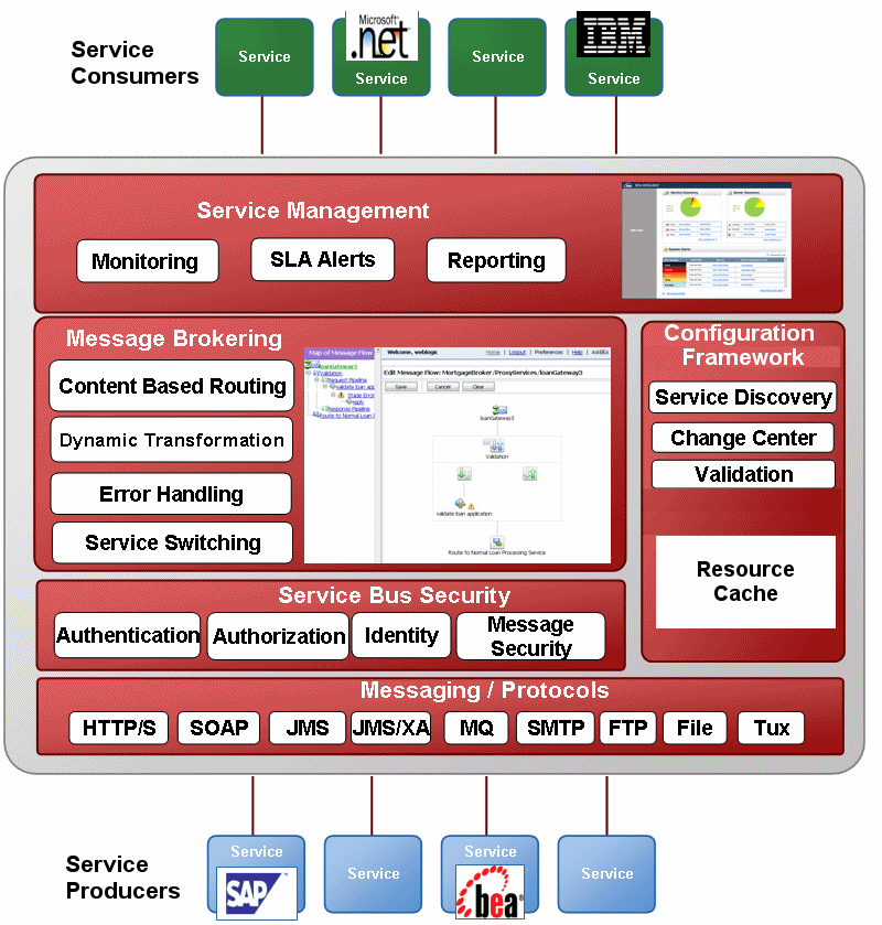
The following high-level architecture diagram illustrates AquaLogic Service Bus and its functional subsystems: service management, message brokering, configuration framework, security and transport layer, and messaging protocols.

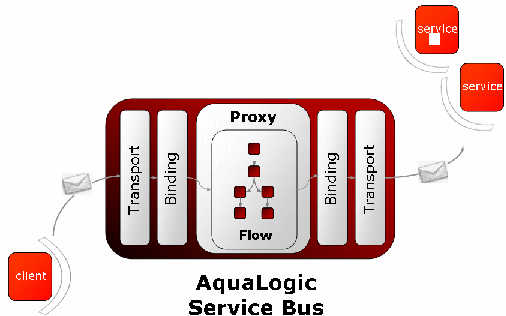
Messages can contain data or status information about application processes, or instructions for the recipient, or both. AquaLogic Service Bus enables you to route messages based on their contents and to perform transformations on that content. The processing happens through the transport and binding layers of AquaLogic Service Bus.

The processing of messages occurs in the following sequence of events:
After a message is sent to an endpoint (either a business service or another proxy service), AquaLogic Service Bus processes the response message in a similar model as that described in the preceding sequence of events.
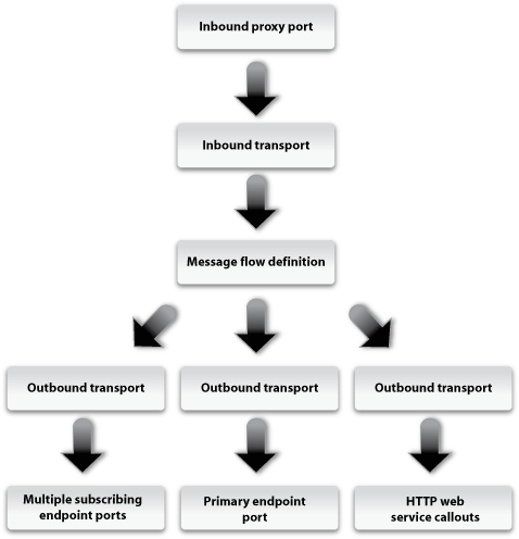
The following figure illustrates a high-level message flow process through the AquaLogic Service Bus, from inbound endpoint (proxy service) to outbound endpoint (service transport URL - a business service or another proxy service).

The following sections describe each layer involved in this message processing.
The inbound transport layer is the communication layer between client services (or service consumers) and AquaLogic Service Bus. It is responsible for handling communication with the service client endpoint and acts as the entry point for messages into AquaLogic Service Bus. The inbound transport layer primarily deals with raw bytes of message data in the form of input/output streams.It provides support for compatible transport protocols, including HTTP(S), JMS, FTP, File, and E-mail. It is not involved in data processing but is responsible for returning response messages to service consumers and handles meta-data for messages, including endpoint URIs, transport headers, etc.
The outbound transport layer is responsible for the communication between business services (or service producers) and AquaLogic Service Bus. It is responsible for moving messages from AquaLogic Service Bus to the business service or proxy service and for receiving the response from the services. The message data, at the transport level, is in raw bytes in the form of input/output streams. The outbound transport layer provides support for compatible transport protocols, including HTTP(S), JMS, FTP, File, and E-mail. It is not involved in data processing but handles meta-data for messages, including endpoint URIs, transport headers, etc.
Proxy services are a fundamental concept in the architecture of BEA AquaLogic Service Bus. They are the interface that service consumers use to connect with managed back-end services. Proxy services are definitions of intermediary Web services that the Service Bus implements locally. BEA AquaLogic Service Bus Console allows configuration of a proxy service by defining its interface in terms of Web Services Description Languages (WSDLs) and the type of transport it uses. Message processing logic is specified in message flow definitions when defining a proxy service. For more information on proxy services, see Proxy Services.
The context of a proxy service is a set of XML variables that are shared across the request flow and response flow. New variables can be dynamically added or deleted to the context. Predefined context variables contain information about the message, transport headers, security principles, metadata for the current proxy service, and metadata for the primary routing and publishing services invoked by the proxy service.
The context can be read and modified by XQuery expressions and updated by transformation and in-place update actions. The core of the context contains the variables $header, $body, and $attachments. These wrapper variables contain the Simple Object Access Protocol (SOAP) header elements, SOAP body element, and Multipurpose Internet Mail Extensions (MIME) attachments, respectively. The context gives the impression that all messages are SOAP messages, and non-SOAP messages are mapped to this paradigm.
Since a proxy service can route messages to multiple business services, a proxy service can be configured with an interface that is independent of the business services it communicates with. Using generic proxy templates, the proxy service can be a configured as a message-flow definition that dynamically routes messages to appropriate business services based on content-based routing logic.A proxy service can also map message data into appropriate protocol formats required by the end-point business service, allowing for dynamic run-time protocol switching.
For more information on proxy templates, see Service Composition in the Concepts and Architecture Guide.
The implementation of a proxy service is specified by a message flow definition. The message flow defines the flow of request and response messages through the proxy service. The following four elements are used to construct a message flow:
Message flow elements can be combined in arbitrary ways to form a tree structure with the start node always (and only) occurring as the root of the tree and the route nodes. The last nodes in a branch (leaf nodes) may be route nodes or echo nodes. The request message starts at the start node and follows a path to a leaf node, executing actions in the request pipelines. If the leaf is a route node, a response is generated (could be empty if the service is a one way service). If the leaf is an echo node, the request is also considered to be the response. The response follows the inverse path in the tree skipping actions in the branch nodes, but executing actions in response pipelines. A response is then finally sent from the top of the tree, if the interface or operation was request/response; otherwise the response is discarded. For more information on message flow definitions, see Modeling Message Flow in AquaLogic Service Bus in BEA AquaLogic Service Bus User Guide.
A set of transformations that affects context variables can be defined before the message is sent to the selected endpoint or after the response is received. A Web services callout can be an alternative to an XQuery or XSLT transformation to set the context variable. For information on how to configure AquaLogic Service Bus transformation maps, see Transforming Data Using the XQuery Mapper.
WS-Security processing as well as authorization is transparently performed at the Start node, when invoking a business service with a WS-policy. For information on how to configure AquaLogic Service Bus security, see the AquaLogic Service Bus Security Guide.
By fusing the concepts of the ESB, message brokering, and operational services management into a single product, BEA AquaLogic Service Bus allows management and integration of messages and services across a services network. Its core functional features are separated into the following categories:
To support heterogeneous environments, AquaLogic Service Bus accommodates multiple messaging paradigms. It supports the following types of communication:
A high performance message broker is a core component of AquaLogic Service Bus. It enables content-based routing of messages and data transformation. AquaLogic Service Bus message brokering capabilities are implemented with the following operational features:
All routing logic pertaining to communications with a service end point is handled via the configured proxies. This frees service consumers from having to understand any of the complexities of communicating with back-end services. Decoupling the routing, transformation, security, and transport details from the service consumers and providers and placing them within configurable proxy services, provides for more flexible service integration.
AquaLogic Service Bus supports dynamic content-based routing of messages and run-time protocol selection. It facilitates these capabilities by allowing the configuration of proxy services with interfaces that are independent of the end-point business services. Using generic proxy templates, proxy services can be configured as message-flow definitions with routing logic that dynamically route messages to appropriate business services, based on message content.
AquaLogic Service Bus supports the following capabilities for the transformation or processing of messages:
AquaLogic Service Bus provides a service callout action that offers greater flexibility for more sophisticated message flows for complex dynamic-routing processing, or to perform message enrichment. The service callout action is used inside a message flow routing stage, to call on the destination service to perform some action on the message. The Service Callout functionality supports features such as RPC Encoding and URL replacement and offers extensibility of AquaLogic Service Bus capabilities by using Java Callouts and POJOs. For more information on service callouts, see Constructing Service Callouts in BEA AquaLogic Service Bus User Guide.
AquaLogic Service Bus provides a database lookup function using a new XQuery function in the BEA XQuery engine. This can be used for message enrichment, for routing decisions or for customizing the behavior of a proxy service. Read-access to databases from proxy services is supported without requiring writing of a custom EJB or custom Java code and without the need for a separate database product like AquaLogic Data Services Platform. It is implemented using the execute-sql() function to make a JDBC call to a database to perform simple database reads. For more information, see “Accessing Databases using XQuery” in Modeling Message Flow in AquaLogic Service Bus in BEA AquaLogic Service Bus User Guide.
AquaLogic Service Bus provides optimized transport for 1-way or 2-way communication for invoking services on AquaLogic Data Services Platform Data using a native Data Services Platform (DSP) transport. This allows a more efficient and flexible approach to accessing data services than exposing them as Web services via WebLogic Workshop and Java Web Services (JWS), and it supports security and identity propagation. For information on DSP transport, see the ALDSP and ALSB Compatibility Matrix.
Two data transformation tools are installed with AquaLogic Service Bus and Workshop for WebLogic—the BEA XQuery Mapper plug-in for Eclipse 3.1 and Format Builder. Eclipse 3.1 and Format Builder are supported on Windows platforms only.
For information about AquaLogic Service Bus interoperability, including information about support for compliance with messaging standards including SOAP, HTTP, JMS, SMTP/POP/IMAP, FTP, SSL, XML, XML Schema, WSDL, WSRP, and WS-Security, see AquaLogic Service Bus Product Support Information.
Business services and Proxy services in AquaLogic Service Bus can be designed to use the EJB transport. The EJB transport is fully integrated into the AquaLogic Service Bus configuration, management, monitoring, and test consoles. Business services built with the EJB transport can be used for Publish, Service Callout, and service invocations.
An EJB can be exposed as a Web service, without the need for tools or the modification of the legacy code on the application server that hosts the EJB. The EJB transport provides the following capabilities:
AquaLogic Service Bus supports open industry standards for ensuring the integrity and privacy of communications and to ensure that only authorized users can access resources in an AquaLogic Service Bus domain. It uses the underlying WebLogic security framework as building blocks for its security services. The WebLogic security framework divides the work of securing a domain into several components (providers), such as authentication, authorization, credential mapping, and auditing.
AquaLogic Service Bus provides the following security features:
The AquaLogic Service Bus security model includes the following:
For more information on the above features of AquaLogic Service Bus security model, see AquaLogic Service Bus Security.
For more information on AquaLogic Service Bus supported standards, see Supported Standards and Security Providers in AquaLogic Service Bus Security Guide.
AquaLogic Service Bus Console Change Center is key to making configuration changes inside the service bus. The Change Center has the unique ability to lock its current configuration while changes are being made, letting the service bus continue to receive and process requests for services while configuration changes are being made in the console. Changes being made to the configuration do not affect the current system configuration until they are “activated”. The service bus uses the new service and resource configuration when changes are activated. This way, ongoing changes can be made without disrupting services.
For more information on Change Center, see Using the Change Center in Using the AquaLogic Service Bus Console.
AquaLogic Service Bus built-in test console is a browser-based test environment used to validate resources and inline XQuery expressions used in the message flow. It is an extension of the AquaLogic Service Bus Console. Using the test console, it is possible to configure the test object (proxy service, business service, XQuery, XSLT, MFL resource), execute the test, and view test results. It allows message flow tracing when testing a service, to examine the state of the message at specific trace points.
Design time testing helps isolate design problems before deploying a configuration to a production environment. The test console can test specific parts of a system in isolation and it can test a system as a unit. The test console can be invoked in a number of ways in the AquaLogic Service Bus Console, from:
For more information, see Using the Test Console in the BEA AquaLogic Service Bus User Guide.
AquaLogic Service Bus provides the following resource management capabilities:
AquaLogic Service Bus provides a number of APIs for customization of service definitions, WSDLs, schemas, XQueries and other design-time resources through programmatic interfaces. The supporting APIs allow loading ZIP files containing resources, in addition to moving, renaming, cloning, or deleting resources, folders and projects. For more information, see AquaLogic Service Bus APIs in the BEA AquaLogic Service Bus User Guide.
Proxy services developed in BEA AquaLogic Service Bus can be published to a UDDI registry. AquaLogic Service Bus can interact with any UDDI 3.0 compliant registry including AquaLogic Service Registry.
Service definitions in AquaLogic Service Bus can be synchronized (both ways) with those in UDDI. Services can be auto-published to UDDI after they are created or changed within AquaLogic Service Bus and business service definitions can be imported from UDDI.
Business services in AquaLogic Service Bus are also automatically updated (with no human intervention) when the original service is changed in UDDI. Alternatively, the AquaLogic Service Bus Console can be configured to prompt users for approval for synchronization when a service changes in the UDDI registry. For more information about UDDI registries, see UDDI in BEA AquaLogic Service Bus User Guide and the AquaLogic Service Registry documentation.
AquaLogic Service Bus supports the following error handling capabilities:
AquaLogic Service Bus allows the following capabilities for auditing and monitoring services:
The AquaLogic Service Bus Console provides a cluster-wide view of service status and statistics. Both business services and AquaLogic Service Bus proxy services are monitored, as are response times, message counts, and error counts.
JMX Monitoring API provided as a polling interface for the retrieval of metrics. This API enables integration with management partners and enables customers who have their own monitoring consoles to display metrics that can be used for performance analysis.
The AquaLogic Service Bus Console supports tasks performed by users in the operator (IntegrationOperator) role. It provides operational functions and settings that allow users to easily search for resources using the new SMart Search functionality, monitor SLA alerts, pipeline alerts, logs, reports, turn tracing on and off, and to enable and disable services.
Users can readily distinguish between SLA and pipeline alerts since the metrics reported for each are distinguished on the console and via the JMX monitoring APIs. Service-level flags and global flags help control alerting (SLA & pipeline), reporting, and logging. Operators have privileges to edit operational settings, create new SLA alert rules, and create and edit alert destination resources.
For more information on console operational tasks, see AquaLogic Service Bus Operations Guide.
AquaLogic Service Bus provides the ability to deploy new versions of services and allows you to have multiple versions of message resources such as WSDLs and schemas. Versions can include changes to the WSDL, the message schema, the headers, and the security parameters.
In AquaLogic Service Bus, monitoring statistics are gathered locally and aggregated centrally. SLA rules are run against aggregated data and the system raises alerts, following which services can be enabled or disabled. Administrators can set service level agreements (SLAs) on the following attributes of proxy services:
AquaLogic Service Bus is designed to centrally manage and control many distributed service endpoints. AquaLogic Service Bus runs on WebLogic Server version 9.0 or greater, and can be deployed in the following configurations:
Using AquaLogic Service Bus you can configure autonomous ESB instances across the enterprise. These instances have their own sets of configuration artifacts such as services and transformations. Such deployments typically map to various IT departments within an organization. Communication between different departments is achieved through a federated network of ESBs, which talk to each other, often through firewalls. For more information on BEA AquaLogic Service Bus deployment, see BEA AquaLogic Service Bus Deployment Guide.
AquaLogic Service Bus enables management and coordination of many distributed service endpoints, thereby providing centralization in the enterprise. It is possible to horizontally scale heterogeneous AquaLogic Service Bus hubs by clustering the underlying WebLogic Server, to create a distributed AquaLogic Service Bus network.
A cluster consists of a set of clustered managed servers that perform message processing. A domain can have only one cluster with AquaLogic Service Bus deployed to it. This cluster can host other applications in addition to AquaLogic Service Bus. There is one administration server in every clustered domain. For more information on clustering, see Understanding AquaLogic Service Bus Clusters in BEA AquaLogic Service Bus Deployment Guide.
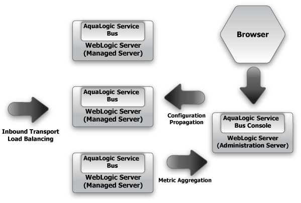
In this case, a central deployment of AquaLogic Service Bus is used for governance and coordination, and every ESB in the network communicates through the central ESB. It propagates configuration and metadata automatically to the managed servers for fast local retrieval, and it automatically collects monitoring metrics from all the managed servers for aggregation and displays them on the AquaLogic Service Bus Console.
The following figure shows the flow of message data in a basic AquaLogic Service Bus cluster topology.

AquaLogic Service Bus enables reliable and guaranteed messaging through the federated network through JMS store and forward. The dynamic routing capability also simplifies configuration of such a network. Spreading the messaging load homogeneously over the clustered servers prevents bottlenecks in the system.
AquaLogic Service Bus supports best practices for change management in enterprise systems by configuration of resources and services in a controlled environment. It allows export of system configurations into separate staging domains for testing and final preparation for promotion into a production domain. Java programs or scripts can be used to automate deploying an application or for moving a configuration from staging to production.
The AquaLogic Service Bus Console has options for numerous deployment customization options. An extended list of environment variables allows settings to be preserved or tailored when moving from one environment to another. For more information, see “Finding and Replacing Environment Values" and "Creating Customization Files" in Customization in Using the AquaLogic Service Bus Console.
An important part of large scale development is the ability to develop, test, stage, and deploy resources to a production system. AquaLogic Service Bus Console enables AquaLogic Service Bus resource configurations to be saved as metadata and exported in JAR files to other AquaLogic Service Bus domains. This functionality supports an orderly promotion process of AquaLogic Service Bus resource configurations from staging and test environments into production and minimizes the expertise, time, and resources needed to achieve various deployment scenarios.
In addition to exporting and importing resources, it is also permitted to export and import entire projects. Using the features of existing source code control system in conjunction with the configuration JAR files, provides version and change management for AquaLogic Service Bus configurations.
The Export feature provides the ability to export existing configurations using a JAR file, to another AquaLogic Service Bus domain. This capability allows system configuration to be propagated from one instance of AquaLogic Service Bus to another instance by exporting all, or a subset of, the resources deployed in the source AquaLogic Service Bus domain. There are no restrictions on what can be exported. One or more projects, or select resources from one or more projects can be exported.
The AquaLogic Service Bus Console also allows export of a resource and all the other resources on which it depends, using the dependency tracking feature. It is necessary to be working outside a session to export configurations. Only configurations that have been activated (that is, deployed to run time) can be exported.
There are two types of operational values: Global Operational Settings and operational values for proxy and business services. Global Operational Settings is a resource located in the System project folder and can be exported like any other resource. It is possible to preserve operational settings in the importing domain from being overwritten during import. This is achieved by specifying the `Preserve Operational Values' setting. If `Preserve Operational Values' is not specified, the values from the JAR file being imported are set in the domain.
The Import feature provides the ability to import resource configurations into a session on another AquaLogic Service Bus domain. To use the Import feature, it is necessary to be working in the session into which the configuration JAR file is to be imported. Many configuration updates and import of multiple JAR files is permitted in a single session. It is also possible to import only a subset of the exported data.
AquaLogic Service Bus provides the ability to reconfigure environment-specific elements as necessary to meet the requirements of the importing domain, using the Change Center in the AquaLogic Service Bus Console. Using this customization feature, imported resources can be tailored for the new domain before activating them.
It supports the global change of environment-specific attributes for resources, using the import functionality along with the find and replace feature. This facilitates changing of many similar environment values in a convenient way. It is not meant to replace a more careful tuning of configuration that may be required by complex deployment scenarios. For more information, see Best Practices for Deploying AquaLogic Service Bus Resources.
For information on how to export and import configuration metadata using the AquaLogic Service Bus Console, see C ustomization in the Using the AquaLogic Service Bus Console. For information on how to modify configurations for new environments using the AquaLogic Service Bus Console Change Center, see Using the Change Center in the Using the AquaLogic Service Bus Console.
Though all AquaLogic Service Bus configuration and deployment can be performed using the AquaLogic Service Bus Console, the WebLogic Server Scripting Tool (WLST) can be used to automate deployment tasks. For information about WLST, see WLST Command and Variable Reference in WebLogic Scripting Tool.


|