| Oracle® Application Server Adapters for Files, FTP, Databases, and Enterprise Messaging User's Guide 10g Release 3 (10.1.3.1.0) Part Number B28994-02 |
|
|
View PDF |
| Oracle® Application Server Adapters for Files, FTP, Databases, and Enterprise Messaging User's Guide 10g Release 3 (10.1.3.1.0) Part Number B28994-02 |
|
|
View PDF |
This chapter describes how to use the Oracle Application Server Adapter for Java Message Service (JMS adapter), which enables a BPEL process or an ESB service to interact with JMS.
This chapter contains the following topics:
Section 5.2, "JMS Adapter Use Cases for Oracle BPEL Process Manager"
Section 5.3, "JMS Adapter Use Cases for Oracle Enterprise Service Bus"
The JMS architecture uses one client interface to many messaging servers. The JMS model has two messaging domains: point-to-point and publish-subscribe. In the point-to-point domain, messages are exchanged through a queue and each message is delivered to only one receiver. In the publish-subscribe model, messages are sent to a topic and can be read by many subscribed clients. For JMS adapter example files, go to
Oracle_Home\bpel\samples\tutorials\123.JmsAdapter
This section comprises the following topics:
The JMS adapter includes the following features:
Based on JMS version 1.0.2b
Is a generic JMS adapter and can work with any JMS provider. It has been certified against OEMS JMS, TIBCO JMS, and IBM Websphere MQSeries. (JMS providers OJMS 8.1.7, 9.0.1.4, and 9.2, and IBM MQSeries JMS 5.2 and 5.3).
Supports JMS topics and queues
Supports byte and text message types only in this release. The Adapter Configuration Wizard provides the Native Format Builder Wizard for consuming native data payloads at run time. The Native Format Builder Wizard creates XSD definitions for the underlying native data.
Supports JMS headers and properties
Supports the JMS message selector for performing filtering while subscribing to JMS topics and queues. This parameter is based on the SQL 92 language for filtering messages based on fields present in the JMS header and properties section.
Supports specifying a durable JMS subscriber
Supports persistent and nonpersistent modes of a JMS publisher
Connection retry functionality for MQ provider is currently not supported
Outbound retry functionality for AQJMS on Solaris is not supported
Note:
When you use the JMS adapter to connect to an AQJMS provider, and if the database that hosts the AQ destination is 10.1.0.4, then the adapter retry mechanism on the outbound direction will fail to reconnect to the database server if the database server goes down. This is because of a client JDBC issue withojdbc14.jar. The resolution to this issue involves downloading the 10.1.0.4 JDBC drivers and using them in the mid tier by replacing the libraries, specifically ojdbc14.jar in $MIDTIER_ORACLE_HOME/jdbc. To resolve this issue, refer to Metalink Note 317385.1 for detailed explanation.The JMS API specifies three types of acknowledgments that can be sent by the JMS publisher:
DUPS_OK_ACKNOWLEDGE, for consumers that are not concerned about duplicate messages
AUTO_ACKNOWLEDGE, in which the session automatically acknowledges the receipt of a message
CLIENT_ACKNOWLEDGE, in which the client acknowledges the message by calling the message's acknowledge method
A transaction enables an application to coordinate a group of messages for production and consumption, treating messages sent or received as a single unit. When an application commits a transaction, all messages it received within the transaction are removed by the JMS provider. The messages it sent within the transaction are delivered as one unit to all JMS consumers. If the application rolls back the transaction, the messages it received within the transaction are returned to the messaging system and the messages it sent are discarded. The JMS adapter supports JMS transactions. A JMS-transacted session supports transactions that are located within the session. A JMS-transacted session's transaction does not have any effects outside of the session.
Adapter Framework is used for the bidirectional integration of the J2CA 1.5 resource adapters with BPEL Process Manager. Adapter Framework is based on standards and employs the Web service Invocation Framework (WSIF) technology for exposing the underlying J2CA interactions as Web services.
See Oracle Application Server Adapter Concepts for information on JMS adapter architecture, adapter integration with Oracle BPEL Process Manager, and adapter deployments.
Oracle Enterprise Service Bus supports the Oracle adapters and enables you to define inbound and outbound adapter services for each. An inbound adapter service receives data from an external data source and transforms it into an XML message. An outbound adapter service sends data to a target application by transforming an XML message into the native format of the given adapter.
In the case of JMS adapter service, using Oracle Enterprise Service Bus you can send or receive messages from a JMS queue or topic.
BPEL pre-dates ESB and most of this guide and the samples implicitly assume use with BPEL. However, the adapters work equally well with either BPEL or ESB. For any mention of BPEL here you may substitute ESB instead.
This section comprises the following two use cases:
The following use cases demonstrate the procedure for configuring a JMS adapter and examines the resulting WSDL files and associated oc4j-ra.xml files.
This section comprises the following topics:
Messaging is any mechanism that allows communication between programs. Messages are structured data that one application sends to another. Message-oriented middleware (MOM) is an infrastructure that supports scalable enterprise messaging. MOM ensures fast, reliable asynchronous communication, guaranteed message delivery, receipt notification, and transaction control. JMS is a Java interface developed by Sun Microsystems for producing, sending, and receiving messages of an enterprise messaging system. JMS is an API that JMS vendors implement. Oracle provides two implementations of JMS: OC4J JMS and Oracle JMS based on Oracle advanced queues. A JMS producer creates JMS messages and a JMS consumer consumes JMS messages.
JMS supports two messaging paradigms: point-to-point (queues) and publish/subscribe (topics).
This section comprises the following topics:
In point-to-point messaging, the messages are stored in a queue until they are consumed. One or more producers write to the queue and one or more consumers extract messages from the queue. The JMS consumer sends an acknowledgment after consumption of a message; this results in purging of the message from the queue.
In publish/subscribe messaging, producers publish messages to a topic and the consumer subscribes to a particular topic. Many publishers can publish to the same topic, and many consumers can subscribe to the same topic. All messages published to the topic by the producers are received by all consumers subscribed to the topic. By default, subscribers receive messages only when they are active. However, JMS API supports durable subscriptions that ensure that consumers receive messages that were published even when they are not up and running. The durable subscription involves registering the consumer with a unique ID for retrieving messages that were sent when the consumer was inactive. These messages are persisted by the JMS provider and are either sent to the consumer when it becomes active again or purged from storage if the message expires. The JMS producer can be set either to persistent or nonpersistent mode. The messages are not persisted in the latter case and can be used only for nondurable subscriptions.
Note:
JMS adapter does not remove durable subscriptions after the BPEL partner link, which was using a particular durable subscription, is no longer using it. You need to remove the durable subscribers manually.The JMS API supports both synchronous or asynchronous communication for message consumption. In the synchronous case, the consumer explicitly calls the receive() method on the topic or queue. In the asynchronous case, the JMS client registers a message listener for the topic or queue and the message is delivered by calling the listener's onMessage() method.
Destination, Connection, Connection Factory, and Session
The destination property contains the addressing information for a JMS queue or topic.Connections represent a physical connection to the JMS provider. The connection factory is used to create JMS connections. A session is used to create a destination, JMS producer, and JMS consumer objects for a queue or topic.
Note:
There is a known limitation in OC4J JMS; on a single OC4J JMS connection listener, you cannot have a subscriber and publisher to the same topic. Hence, BPEL processes pubslishing and subscribing to the same topic cannot have the same connection, that is, they cannot share the same JNDI. The workaround to this issue is either of the following:Use different JNDI connection factories (different location attribute values in the WSDL jca:address element)
In the jca:operation element of the WSDL specify useMessageListener=false (can also be set through Oracle JDeveloper JMS Adapter Wizard)
Structure of a JMS Message
The JMS message has a mandatory standard header element, optional properties element, and optional standard payload element. The payload can be a text message, byte message, map message, stream message, or object message. The properties element is JMS provider-specific and varies from one JMS provider to another.
Table 5-1 describes the JMS header properties.
Table 5-1 JMS Header Properties
| Property Name | Description |
|---|---|
|
|
The destination to which the message is sent, and is set by the JMS producer |
|
|
Set to persistent or nonpersistent mode by the JMS consumer |
|
|
Duration of the message before the expiration is set by the consumer |
|
|
Number between |
|
|
Unique message identifier set by the consumer |
|
|
Time stamp when the message was sent to the JMS provider for forwarding |
|
|
Set by both producers and consumers for linking the response message with the request message. This is an optional attribute. |
|
|
Optional attribute indicating the destination to which to send a message reply. Can be set by the producer and consumer. |
|
|
JMS message type |
|
|
Set by the JMS provider to indicate that the provider has tried to send this message once before to the consumer and has failed |
This section describes how to create an adapter service for a partner link.
Click Define Adapter Service (third icon) in the Create Partner Link window, as shown in Figure 5-1:
The Adapter Configuration Wizard - Welcome window is displayed, as shown in Figure 5-2.
Figure 5-2 Welcome Window for the Adapter Configuration Wizard
Note:
If you do not want to see this window each time you use the Adapter Configuration Wizard, select the Skip this Page Next Time check box.Click Next.
The Adapter Type dialog box is displayed, as shown in Figure 5-3.
Select JMS Adapter from the list of available adapter types, and then click Next.
The Service Name window is displayed, as shown in Figure 5-4.
Enter a name for the service. You may also add an optional description. Click Next.
The JMS Provider dialog box is displayed, as shown in Figure 5-5.
Select any one operation. In this operation select Oracle Enterprise Messaging Service (OEMS), and then select Database.
Oracle Enterprise Messaging Service (OEMS): This allows you to integrate with Oracle's memory, file or database messaging service.
Third Party: Select this option to integrate with a third party provider.
Click Next.
The Service Connection dialog box is displayed, as shown in Figure 5-6.
Figure 5-6 Creating a New Database Connection
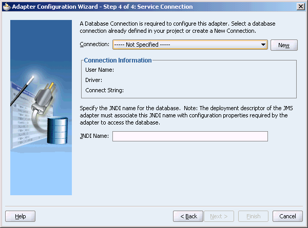
Enter the Java Naming and Directory Interface (JNDI) name in the Database Server JNDI Name field. The JNDI name acts as a placeholder for the connection used when your service is deployed to the BPEL server. This enables you to use different databases for development and later production.
See Also:
Oracle Application Server Adapter Concepts for understanding JNDI conceptsClick New to define a database connection.
The Create Database Connection Wizard is displayed.
Note:
You must connect to the database where Oracle Applications is running.Click Next.
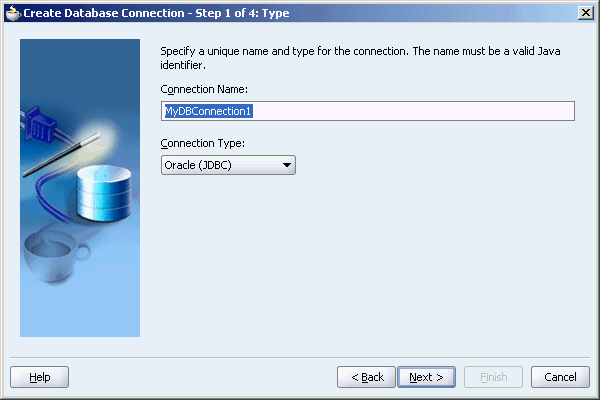
Enter the following information in the Type dialog box:
In the Connection Name field, specify a unique name for the database connection. In this example, type MyDBConnection1.
From the Connection Type box, select the type of connection for your database connection. In this example, retain the default connection type, Oracel (JDBC).
Figure 5-7 shows the Type dialog box.
Figure 5-7 Specifying the Connection Name and Type of Connection
Click Next. The Authentication dialog box is displayed.
Enter information in the following fields:
In the UserName field, specify a unique name for the database connection. In this example, type scott.
In the Password field, specify a password for the database connection. In this example, type tiger.
Note:
You should have access to SCOTT schema in some database.Click Next. The Connection dialog box is displayed.
Enter information in the following fields:
From the Driver list, select Thin.
In the Host Name field, specify the host name for the database connection.
In the JDBC Port field, specify the port number for the database connection. In this example, enter 1521.
In the SID field, specify a unique SID value for the database connection. In this example, enter ORCL.
Click Next.
The Test dialog box is displayed.
Click Test Connection to determine whether the specified information establishes a connection with the database.
Click Finish to complete the process of creating a new database connection.
The Service Connection dialog box is displayed, providing a summary of the database connection, as shown in Figure 5-8.
Click Next.
The Operation dialog box is displayed.
Select Consume Message or Produce Message. In this example, select Consume Message.
The operation name is filled in automatically, as shown in Figure 5-9.
The Consume Message option enables the adapter to consume (receive) inbound messages from a JMS destination.
Click Next.
The Consume Operation Parameters dialog box is displayed, as shown in Figure 5-10.
Figure 5-10 The Consume Operation Parameters Dialog Box
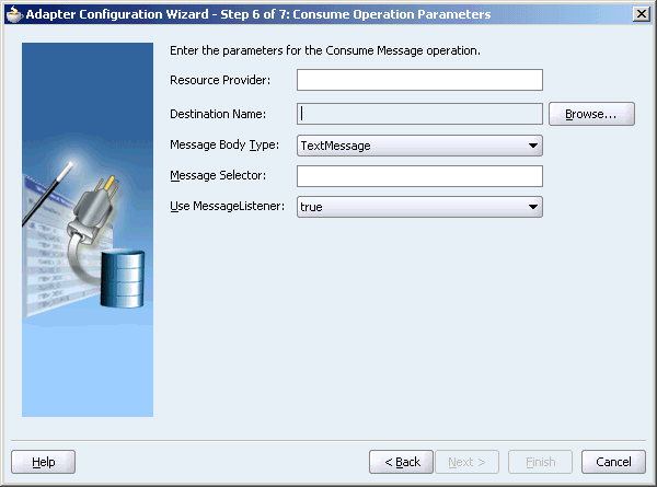
Enter values for the following fields:
Resource Provider
OC4J provides a ResourceProvider interface to transparently plug in JMS providers. The ResourceProvider interface of OC4J allows EJBs, servlets, and OC4J clients to access many different JMS providers. The resources are available under java:comp/resource/. Oracle JMS is accessed using the ResourceProvider interface.
Thus, the resource provider must be entered by the user for OJMS (database option) in the JMS Adapter Wizard
Destination Name
This is the JNDI name of the JMS queue or topic from which to receive the message. This is not an editable field. You must click Browse to browse for the queue or topic. The queue or topic to be chosen is based on the type of JMS provider you are using. See the following sections for details:
Message Body Type
Select either TextMessage or BytesMessage.
The StreamMessage and MapMessage message types are not supported in this release.
Durable Subscriber ID
This field is optional. If you are setting up a durable subscriber, then the durable subscriber ID is required. Normally a subscriber loses messages if it becomes disconnected, but a durable subscriber downloads stored messages when it reconnects.
Note:
When the JMS provider is memory, file or database messaging service, the Durable Subscriber option will show up only when a topic is selected. However, the Durable Subscriber option always appears when the JMS provider is third party.Message Selector
This field is also optional. It filters messages based on header and property information. The message selector rule is a Boolean expression. If the expression is true, then the message is consumed. If the expression is false, then the message is rejected.
For example, you can enter logic, such as:
JMSPriority > 3. Based on this, messages with a priority greater than 3 are consumed; all other messages are rejected.
JMSType = 'car' AND color = 'blue' AND weight > 2500
Country in ('UK', 'US', 'France')
Use MessageListener
This field is set to true by default, which means that the server does an asynchronous callback to the adapter. If this is set to false, then the adapter performs a synchronous blocking receive.
Note:
This example shows a consume message operation. For a produce message operation, this window is different. See Produce Message Procedure to see how this part of the procedure differs.After you enter the appropriate parameters, click Next.
The Messages dialog box is displayed, as shown in Figure 5-11. The settings in this dialog box define the correct schema for the message payload.
You can perform one of the following:
Check Native format translation is not required (Schema is Opaque), which disables the rest of the fields.
Click Define Schema for Native Format to start the Native Format Builder Wizard, which guides you through the process of defining the native format.
Enter the path for the schema file URL (or browse for the path).
The following steps demonstrate the last option: browsing for the schema file URL.
Click the Browse button.
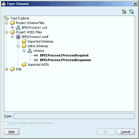
The Type Chooser window is displayed, with the Type Explorer navigation tree, as shown in Figure 5-12.
Browse the tree and select the appropriate schema type, and then click OK.
Figure 5-12 Selecting a Schema from the Type Chooser Window
The Messages window is displayed again, this time with the Schema File URL field and the Schema Element field filled up, as shown in Figure 5-13.
Click Next.
The Finish window is displayed. This box shows the path and name of the adapter file that the wizard creates.
Click Finish.
The Create Partner Link window is displayed with the fields populated, as shown in Figure 5-14.
Figure 5-14 Completed Create Partner Link Window
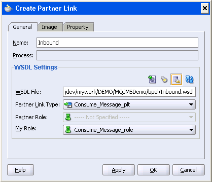
Click OK.
The following WSDL file is generated by the Adapter Configuration Wizard:
<definitions
     name="JMS_Example"
     targetNamespace="http://xmlns.oracle.com/pcbpel/adapter/jms/JMS_Example/"
     xmlns="http://schemas.xmlsoap.org/wsdl/"
     xmlns:tns="http://xmlns.oracle.com/pcbpel/adapter/jms/JMS_Example/"
     xmlns:plt="http://schemas.xmlsoap.org/ws/2003/05/partner-link/"
     xmlns:jca="http://xmlns.oracle.com/pcbpel/wsdl/jca/"
     xmlns:opaque="http://xmlns.oracle.com/pcbpel/adapter/opaque/"
     xmlns:pc="http://xmlns.oracle.com/pcbpel/"
     xmlns:hdr="http://xmlns.oracle.com/pcbpel/adapter/jms/"
    >
This code segment defines the name of the adapter, and the locations of various necessary schemas and other definition files.
<import namespace="http://xmlns.oracle.com/pcbpel/adapter/jms/"
 location="jmsAdapterInboundHeader.wsdl"/>
This code segment imports the necessary namespace.
<types>
    <schema targetNamespace="http://xmlns.oracle.com/pcbpel/adapter/opaque/"
            xmlns="http://www.w3.org/2001/XMLSchema" >
      <element name="opaqueElement" type="base64Binary" />
    </schema>
    </types>
    <message name="Consume_Message_msg">
        <part name="opaque" element="opaque:opaqueElement"/>
    </message>
    <portType name="Consume_Message_ptt">
        <operation name="Consume_Message">
            <input message="tns:Consume_Message_msg"/>
        </operation>
    </portType>
This code segment defines the message type, name, and the port type for the partner link.
<binding name="Consume_Message_binding" type="tns:Consume_Message_ptt">
    <pc:inbound_binding />
        <operation name="Consume_Message">
      <jca:operation
          ActivationSpec="oracle.tip.adapter.jms.inbound.JmsConsumeActivationSpec"
          DestinationName="jms/DemoQue"
          UseMessageListener="true"
          PayloadType="TextMessage"
          OpaqueSchema="true" >
      </jca:operation>
      <input>
        <jca:header message="hdr:InboundHeader_msg" part="inboundHeader"/>
      </input>
        </operation>
    </binding>
This code segment defines the necessary bindings for the consume message operation, the target queue, and identifies the message header.
<service name="JMS_Example2">
        <port name="Consume_Message_pt" binding="tns:Consume_Message_binding">
      <jca:address location="eis/Jms/topics.xml" />
        </port>
    </service>
  <plt:partnerLinkType name="Consume_Message_plt" >
    <plt:role name="Consume_Message_role" >
      <plt:portType name="tns:Consume_Message_ptt" />
    </plt:role>
  </plt:partnerLinkType>
</definitions>
This last part defines the database connection, the connection factory (as defined in the oc4j-ra.xml file), and the name and role of the partnerLinkType and portType.
The oc4j-ra.xml file defines the endpoints for the JMS connection factories. The connection factories include configuration properties for each endpoint. Endpoints are added to accommodate different types of connections, as demonstrated in the following sections. The following example is from the generic oc4j-ra.xml file:
<?xml version="1.0"?>
<!DOCTYPE oc4j-connector-factories PUBLIC "-//Oracle//DTD Oracle Connector
 9.04//EN" "http://xmlns.oracle.com/ias/dtds/oc4j-connector-factories-9_04.dtd">
<oc4j-connector-factories>
     <connector-factory location="eis/MyJmsTopic1" connector-name="Jms Adapter">
     <config-property name="connectionFactoryLocation"
                      value="jms/TopicConnectionFactory"/>
     <config-property name="factoryProperties" value=""/>
     <config-property name="acknowledgeMode" value="AUTO_ACKNOWLEDGE"/>
     <config-property name="isTopic" value="true"/>
     <config-property name="isTransacted" value="true"/>
     <config-property name="username" value="admin"/>
     <config-property name="password" value="welcome"/>
</connector-factory>
<connector-factory location="eis/MyJmsTopic2" connector-name="Jms Adapter">
     <config-property name="connectionFactoryLocation"

...
</oc4j-connector-factories>
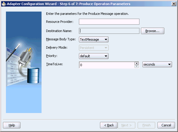
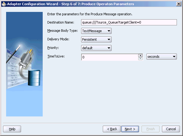
A produce message operation has certain differences in the definition procedure, particularly in Step 19 of Using the Adapter Configuration Wizard to Configure a JMS Adapter. Instead of specifying consume operation parameters, you specify the following produce operation parameters. This enables the adapter to produce (send) outbound messages for a JMS destination. The Produce Operation Parameters window is shown in Figure 5-15.
Destination Name:
The JNDI name of the JMS queue or topic to which to deliver the message. The name to enter is based on the type of JMS provider you are using. See the following sections for detail:
Message Body Type:
The supported values are TextMessage or BytesMessage. The StreamMessage and MapMessage message types are not supported in this release.
Delivery Mode:
The values are Persistent or Nonpersistent. A persistent delivery mode specifies a persistent JMS publisher; that is, a publisher that stores messages for later use by a durable subscriber. A durable subscriber is a consume message with a durable subscriber ID in the corresponding field in step 21 of Using the Adapter Configuration Wizard to Configure a JMS Adapter. A nondurable subscriber loses any messages that are produced when the adapter is not active. A durable subscriber downloads messages that have been stored in the persistent publisher, and therefore does not have to remain active at all times to receive all the messages.
Priority:
Select a priority value, with 9 representing the highest priority and 0 representing the lowest priority. The default is 4.
TimeToLive:
The amount of time before the message expires and is no longer available to be consumed.
Figure 5-15 Produce Operation Parameters Window
Configure the OJMS provider within the resource-provider element in the global application.xml file. You can configure the resource provider with a URL property. The following demonstrates a URL configuration:
<resource-provider class="oracle.jms.OjmsContext" name="ojmsdemo">
     <description>OJMS/AQ</description>
     <property name="url" value="jdbc:oracle:thin:@localhost:1521:my" />
     <property name="username" value="jmsuser" />
     <property name="password" value="jmsuser" />
</resource-provider>
In the oc4j-ra.xml file, add the following code segments:
<connector-factory location="eis/aqjms/Topic" connector-name="Jms Adapter">
     <config-property name="connectionFactoryLocation"
           value="java:comp/resource/ojmsdemo/TopicConnectionFactories/myTCF" />
     <config-property name="factoryProperties" value="" />
     <config-property name="acknowledgeMode" value="AUTO_ACKNOWLEDGE" />
     <config-property name="isTopic" value="true" />
     <config-property name="isTransacted" value="true" />
     <config-property name="username" value="jmsuser" />
     <config-property name="password" value="jmsuser" />
</connector-factory>
<connector-factory location="eis/aqjms/Queue" connector-name="Jms Adapter">
    <config-property name="connectionFactoryLocation" value="
         java:comp/resource/ojmsdemo/QueueConnectionFactories/myQCF" />
    <config-property name="factoryProperties" value="" />
    <config-property name="acknowledgeMode" value="AUTO_ACKNOWLEDGE" />
    <config-property name="isTopic" value="false" />
    <config-property name="isTransacted" value="true" />
    <config-property name="username" value="jmsuser" />
    <config-property name="password" value="jmsuser" />
</connector-factory>
In this case, correct JMS connection JNDI names for Step 7 of Using the Adapter Configuration Wizard to Configure a JMS Adapter are eis/aqjms/Topic or eis/aqjms/Queue.
Set the isTransacted value in the oc4j-ra.xml file to true. Setting it to false leads to exception errors.
Access the OJMS Resources
java:comp/resource + JMS_provider_name + TopicConnectionFactories + user_defined_name
java:comp/resource + JMS_provider_name + QueueConnectionFactories + user_defined_name
The OJMS syntax for the connection factory is as follows:
or
The user_defined_name can be anything and does not match any other configuration. The ConnectionFactories details what type of factory is being defined. For this example, the JMS provider name is defined in the resource-provider element as ojmsdemo.For a queue connection factory: Because the JMS provider name is ojmsdemo and you decide to use a name of myQCF, the connection factory name is java:comp/resource/ojmsdemo/QueueConnectionFactories/myQCF. For a topic connection factory: Because the JMS provider name is ojmsdemo and you decide to use a name of myTCF, the connection factory name is java:comp/resource/ojmsdemo/TopicConnectionFactories/myTCF. The user-defined names of myQCF and myTCF are not used for anything else in your logic. Therefore, you can choose any name.
Destination
The OJMS syntax for any destination is as follows:
java:comp/resource + JMS_provider_name + Topics + Destination_name
or
java:comp/resource + JMS_provider_name + Queues + Destination_name
The topic or queue details which type of destination is being defined. The destination name is the actual queue or topic name defined in the database.For this example, the JMS provider name is defined in the resource-provider element as ojmsdemo. In the database, the queue name is aqQueue.For a queue: If the JMS provider name is ojmsdemo and the queue name is aqQueue, the JNDI name for the queue is java:comp/resource/ojmsdemo/Queues/aqQueue.For a topic: If the JMS provider name is ojmsdemo and the topic name is aqTopic, the JNDI name for the topic is java:comp/resource/ojmsdemo/Topics/aqTopic.
OJMS and Remote Databases
To configure the adapter to use a remote database, the entries in the application.xml file must look as follows:
<resource-provider class="oracle.jms.OjmsContext" name="ojmsdemo">
<description>OJMS/AQ</description>
<property name="url"
value="jdbc:oracle:thin:@remote-host:remote-port:remote-sid" />
<property name="username" value="jmsuser" />
@ <property name="password" value="jmsuser" />
</resource-provider>
If the OC4J JMS server is running on another remote host, you can configure the JMS adapter to talk to the server by using the following connector entry. Note that the only difference with this connector entry is in the factory properties. The factory properties can establish a JNDI context for the adapter. Substitute [hostname] with the hostname of the server on which the OC4J JMS server is running. If the RMI port of the remote OC4J instance is not the default value (23791), you must specify the RMI port in the provider URL (that is, ormi://remotehost.domain.com:23795).
<connector-factory location="eis/RemoteOC4JJMS/Queue"
connector-name="Jms Adapter">
     <config-property name="connectionFactoryLocation"
           value="jms/QueueConnectionFactory" />
     <config-property name="factoryProperties"
value="java.naming.factory.initial=com.evermind.server.ApplicationClientInitialCon
textFactory;java.naming.provider.url=ormi://[hostname];
java.naming.security.principal=admin;java.naming.security.credentials=welcome"/>
     <config-property name="acknowledgeMode" value="AUTO_ACKNOWLEDGE" />
     <config-property name="isTopic" value="false" />
     <config-property name="isTransacted" value="true" />
     <config-property name="username" value="admin" />
     <config-property name="password" value="welcome" />
</connector-factory>
In this case, the correct JMS connection JNDI name for Step 7 of Using the Adapter Configuration Wizard to Configure a JMS Adapter is eis/RemoteOC4JJMS/Queue.
In addition, you must have the file META-INF/application-client.xml in the classpath. The contents of the file can be the following:
<application-client/>
To put this file in the classpath, put the specified contents into the file at Oracle_Home\bpel\system\classes\META-INF\application-client.xml and restart Oracle BPEL Server.
If you set isTransacted to true in the oc4j-ra.xml file for an outbound connection, you receive an error. Do not set this value to true for outbound connections.
Destination Name
The destination name for OC4J JMS is either a JNDI location (for example, jms/demoQueue or jms/demoTopic) or the actual name of the destination as configured in jms.xml (for example, Demo Queue or Demo Topic).
The BPEL OC4J application.xml file should contain the following jar file, where Tibco EMS is installed in C:\tibco\ems. The JMS and JNDI jar files are already present in the classpath and do not need to be included.
<library path=ÓC:\tibco\ems\clients\java\tibjms.jarÓ />
Create the appropriate endpoints for the JMS connection factories in oc4j-ra.xml. After this change is made, restart Oracle BPEL Server. Here are the appropriate code segments. You can modify the necessary parameters and use this for your purpose:
<connector-factory location="eis/tibjms/Topic" connector-name="Jms Adapter">
     <config-property name="connectionFactoryLocation"
           value="TopicConnectionFactory" />
     <config-property name="factoryProperties"
value="java.naming.factory.initial=com.tibco.tibjms.naming.TibjmsInitialContextFa
ctory;java.naming.provider.url=tibjmsnaming://localhost:7222;java.naming.security.
principal=admin;java.naming.security.credentials=password" />
     <config-property name="acknowledgeMode" value="AUTO_ACKNOWLEDGE" />
     <config-property name="isTopic" value="true" />
     <config-property name="isTransacted" value="true" />
     <config-property name="username" value="admin" />
     <config-property name="password" value="password" />
</connector-factory>
<connector-factory location="eis/tibjms/Queue" connector-name="Jms Adapter">
     <config-property name="connectionFactoryLocation"
           value="QueueConnectionFactory" />
     <config-property name="factoryProperties"
value="java.naming.factory.initial=com.tibco.tibjms.naming.TibjmsInitialContextFa
ctory;java.naming.provider.url=tibjmsnaming://localhost:7222;java.naming.security.
principal=admin;java.naming.security.credentials=password" />
     <config-property name="acknowledgeMode" value="AUTO_ACKNOWLEDGE" />
     <config-property name="isTopic" value="false" />
     <config-property name="isTransacted" value="true" />
     <config-property name="username" value="admin" />
     <config-property name="password" value="password" />
</connector-factory>
In this case, correct JMS connection JNDI names for Step 7 of Using the Adapter Configuration Wizard to Configure a JMS Adapter are eis/tibjms/Topic or eis/tibjms/Queue.
When using Tibco JMS, always set the ClientID property as follows in the Oracle_Home\bpel\system\appserver\oc4j\j2ee\home\application-deployments\default\FtpAdapter\oc4j-ra.xml file:
<config-property name="factoryProperties"
    value="ClientID=clientId{time}"/>
The substring {time} instructs the run time to replace it with the value of Java System.currentTimeMillis(). The other supported substitutions are:
{checksum}
A checksum based on the values of the oc4j-ra.xml connection factory properties (referenced through jca:address).
{sequence}
Next member of an increasing series of integers starting at zero.
These settings enable you to specify a fixed or a variable ClientID in oc4j-ra.xml.
The BPEL OC4J application.xml file should contain the following jar files, assuming MQ Series is installed in the C:\mqseries directory.
<library path="C:\mqseries\java\lib\com.ibm.mq.jar" />
<library path="C:\mqseries\java\lib\com.ibm.mqjms.jar" />
Create the appropriate endpoints for the JMS connection factories in oc4j-ra.xml. After this change is made, you must restart Oracle BPEL Server. Here are the appropriate code segments. You can modify the necessary parameters and use this for your purpose.
<connector-factory location="eis/mqseries/Queue" connector-name="Jms Adapter">
     <config-property name="connectionFactoryLocation"
           value="com.ibm.mq.jms.MQQueueConnectionFactory" />
     <config-property name="factoryProperties"
value="QueueManager=my.queue.manager;TransportType=1;HostName=myhost.com;Port=141
       4;Channel=MYCHANNEL" />
     <config-property name="acknowledgeMode" value="AUTO_ACKNOWLEDGE" />
     <config-property name="isTopic" value="false" />
     <config-property name="isTransacted" value="true" />
     <config-property name="username" value="MUSR_MQADMIN" />
     <config-property name="password" value="password" />
</connector-factory>
In this case, the correct JMS connection JNDI name for Step 7 of Using the Adapter Configuration Wizard to Configure a JMS Adapter is eis/mqseries/Queue.
Note:
WebSphere MQ uses the regular Windows username and group authorizations to protectWebSphere MQ applications and WebSphere MQ Administration.
To work with username and group authorizations:
Open the Control Panel, then User Accounts or Users and then Passwords.
On Windows NT, open the User Manager.
WebSphere MQ Installation automatically creates the local group mqm and username MUSR_MQADMIN. Usernames which are members of this group have authority to work with and administer WebSphere MQ queue managers. You can change the password for the user MUSR_MQADMIN, by selecting it and then clicking on Set password. This is the user name and password that should reflect in the oc4j-ra.xml entry, as shown in the following example:
<config-property name="username" value="MUSR_MQADMIN"/>
<config-property name="password" value="password"/>
Destination Name
The destination name is the name of the topic or queue listed in your MQ Series configuration. For example, the name of the queue can be queue:///MYQUEUE?targetClient=0.
The OracleAS Adapter for JMS is part of the Oracle BPEL Process Manager install and is a JCA 1.5 Resource Adapter. The Adapter Framework (AF) is used for the bidirectional integration of the JCA 1.5 resource adapters with BPEL Process Manager. Adapter FW is based on open standards and employs the Web Service Invocation Framework (WSIF) technology for exposing the underlying JCA Interactions as Web Services. This example showcases the following:
A MQSeries Queue Consumer dequeing the message from a MQSeries queue and triggering the BPEL process. The message payload is of type Text and is defined by a delimited schema using the Native Format Builder.
A MQSeries Queue Producer enqueuing the message to a MQSeries Queue based on the invoke BPEL message.
This section describes how to create an adapter service for a partner link.
Follow steps 1 through 3 under Using the Adapter Configuration Wizard to Configure a JMS Adapter.
In Step 4 of Using the Adapter Configuration Wizard to Configure a JMS Adapter, for service name, type Inbound, as shown in Figure 5-16.
Select Third Party as the operation type to integrate with a third party, and then click Next.
The JMS Connection dialog box is displayed.
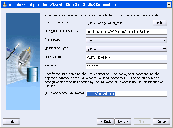
Specify the following connection information in the JMS Connection dialog box.
Factory Properties:
Connection factory location (mcf.ConnectionFactoryLocation) tells the JMS adapter where or how to instantiate either a Queue or a Topic Connection Factory in the underlying JMS provider. First the JMS adapter will try to locate the specified value through JNDI. If that fails, then it considers the value the name of a Java class, which it will then try to instantiate. Only in this case it will also look in the Factory Properties value in mcf.FactoryProperties for any name or value pairs which suggest vendor specific bean methods on the Connection Factory.
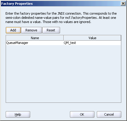
This is a required field, and it is non-editable. Click Edit to enter the factory properties for the JNDI connection, and then click OK.
Figure 5-17 shows the Factory Properties dialog box with the factory properties filled up.
Figure 5-17 Specifying the Factory Properties
JMS Connection Factory:
JMS Connection Factory is used to create JMS Connections. In this example MQQueueConnectionFactory is used to create QueueConnections.
In this example, enter the following value in the JMS Connection Factory field:
com.ibm.mq.jms.MQQueueConnectionFactory
Transacted:
This is a boolean that determines whether the session is transacted or non-transacted.
In this example, retain the default value, true.
Destination Type:
This determines whether destination is a Queue or a Topic.
In this example, retain the default value, Queue.
User Name:
Enter a user name.
Password:
Enter a password.
Figure 5-18 shows the JMS Connection dialog box with all the field populated.
Figure 5-18 The JMS Connection Dialog Box
Click Next.
The Operation dialog box is displayed.
Select Consume, and then click Next.
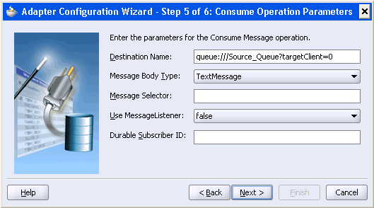
Enter the values in the Consume Operation Parameters dialog box, as shown in Figure 5-19, and then click Next.
The Destination Name field refers to the MQSeries queue name. The value targetClient=0 in the Destination Name field is used indicates that the JMS Header will be part of the message. You have to specify the targetClient value of 1 if you want the JMS Headers to be truncated from the message. The JMS Adapter supports Text and Byte messages. This example uses the Text Message format.
Figure 5-19 The Consume Operation Parameters Dialog Box
In the Messages dialog box, click Browse to select a URL for the schema file. In this example, select expense.xsd, as shown in Figure 5-20.
One of the key features of the JMS Adapter is the support for native format translation into XML and vice-versa. The Adapter payload (Text or Byte) can be pointed to a delimited, fixed-positional, Cobol copy book data and is converted to XML and back by the Native Format Translator. This example points to a delimited schema for the incoming Text Message.
The Adapter Configuration Wizard-Finish screen is displayed.
Click Next, and then click Finish to complete configuring the MQSeries consumer service.
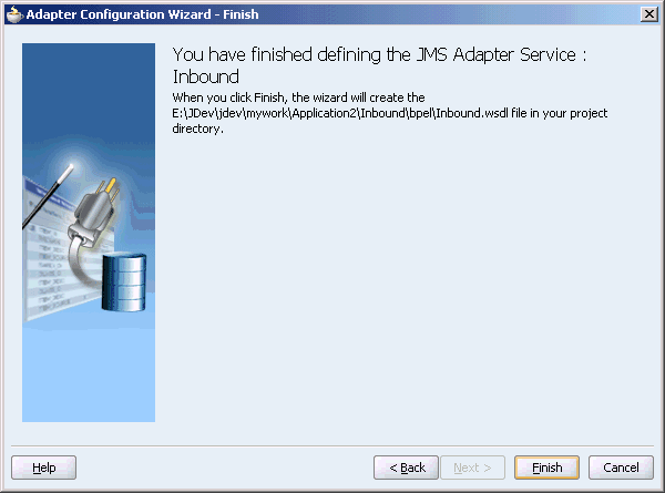
The Finish screen is displayed, as shown in Figure 5-21.
Figure 5-21 FInish Screen or JMS Adapter Service: Inbound
Click Ok in the Create Partner Link dialog box to complete the creation of partner link.
The next step after configuring the MQSeries Consumer Service is to configure the MQSeries Produce Service.
Use the following steps to configure the MQSeries Produce Service:
Follow steps 1 through 3 under Using the Adapter Configuration Wizard to Configure a JMS Adapter.
In Step 4 of Using the Adapter Configuration Wizard to Configure a JMS Adapter, for service name, type Outbound.
Select Third Party as the operation type to integrate with a third party, and then click Next.
The JMS Connection dialog box is displayed.
Specify the connection information in the JMS Connection dialog box, as shown in Figure 5-22.
Figure 5-22 The JMS Connection Dialog Box

Click Produce in the Operation dialog box, and then click Next.
Select Produce, and then click Next.
Enter values in the Consume Operation Parameters dialog box, as shown in Figure 5-23, and then click Next.
Figure 5-23 The Produce Operation Parameters Dialog Box
In the Messages dialog box, click Browse to select a URL for the schema file. In this example, select expense.xsd, as shown in Figure 5-24.
The Adapter Configuration Wizard-Finish screen is displayed.
Click Next, and then click Finish to complete configuring the MQSeries producer service.
The Finish screen is displayed, as shown in Figure 5-25.
Figure 5-25 FInish Screen for JMS Adapter Service: Outbound
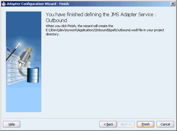
Click Ok in the Create Partner Link dialog box to complete the creation of partner link.
The following are the steps to configure an end-to-end BPEL process:
Click Receive to configure a receive activity to point to the MQSeries Consumer Service.
Figure 5-26 shows the Receive activity.
Figure 5-26 Configuring a Receive Activity
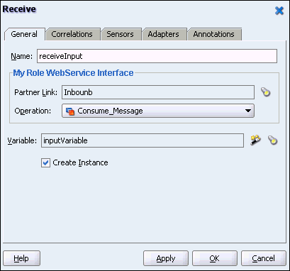
Select the create Instance option, and create a global variable, InputVariable, as shown in Figure 5-26 to receive the incoming message from the MQSeries Consumer.
Click Ok.
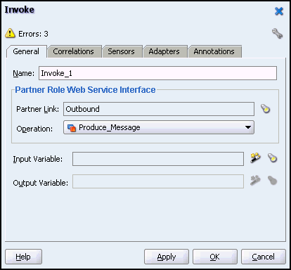
Drag and drop an invoke activity to point to the MQSeries Producer Partner Link.
Figure 5-27 shows the invoke activity.
Figure 5-27 Configuring an Invoke Activity
Drag and drop an assign activity to set the MQSeries Header and Payload message for the MQSeries Producer, and then click OK
Figure 5-28 shows the Assign activity.
Figure 5-28 Configuring an Assign Activity
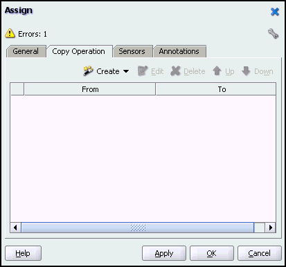
Click the Create drop-down list, and then select Copy Operation, as shown in Figure 5-29.
The Create Copy Operation dialog box is displayed.
Perform copy operations, as shown in Figure 5-30 and Figure 5-31.
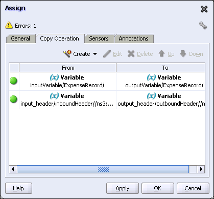
After performing the necessary copy operations, the Assign dialog will look like Figure 5-32.
Figure 5-32 The Assign Dialog Box After Completing Copy Operation
The end-to- end BPEL process looks like Figure 5-33.
This section contains an example that showcases the following:
An ESB service is listening on a JMS topic (OEMS database persistence) for new employee notifications.
Upon receiving such messages it will invoke a stored procedure to insert the new employees in the company database.
The goals of the stated scenario are as follows
Demonstrate how to configure the JMS adapter (inbound) against AQ
Demonstrate how to configure the Database adapter to invoke a PL/SQL stored procedure
Discuss promotion of projects from dev to prod (and related resource providers considerations)
This section comprises the following topics:
Ensure that the following prerequisites are met, before you embark on creating this scenario:
Unzip ESBSamples.zip to C:\ESBSamples or any other location.
Make sure ESBSamples\AQJMStoDB is present
Ensure that the ESBSamples has the tree structure shown in the following Figure 5-34.
Perform the following steps to prepare the Database accounts for creating the scenario:
Open a DOS prompt and change the existing directory to the tutorial directory as shown in the following example:
cd \ESBSamples\AQJMStoDB
Set ORACLE_HOME to the database installation on your computer, as shown in the following example:
ex: set ORACLE_HOME=D:\ORADB_10gR2
Execute the following script to create an account:
sqlplus sys as sysdba @accounts_create.sql
The following are the steps to create a stored procedure:
Change to the sql directory from the existing directory, as shown in the following example:
cd \ESBSamples\AQJMStoDB\sql
Run the following script to create the stored procedure:
sqlplus dbapp/dbapp @procedure_create.sql
Perform the following steps to create in AQ:
Change to the sql directory from the existing directory, as shown in the following example:
cd \ESBSamples\AQJMStoDB\sql
Using the following SQL script to create the necessary infrastructure for a JMS topic named JMSDEMO_TOPIC, in the database:
sqlplus jmuser/jmuser @topic_create.sql
The following are the steps to create a new ESB project:
Open Oracle JDeveloper.
From the File menu, select New.
The New Gallery dialog box is displayed.
Select All Technologies from the Filter By box. This displays a list of available categories.
Expand the General node, and then select Projects.
Select ESB Project from the Items group, as shown in Figure 5-35
Click OK.
The Create ESB Project dialog box is displayed.
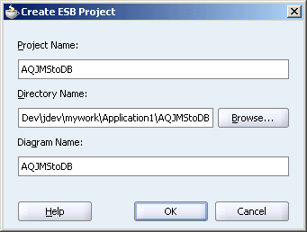
In the Project Name field, enter a descriptive name. For example, AQJMStoDB, as shown in Figure 5-36.
Figure 5-36 Entering the Name of the ESB Project
Click OK.
You have created a new ESB project, titled AQJMStoDB.
The following are the steps to create an inbound JMS adapter:
Select Adapter Services from the Component Palette, and then drag and drop JMS Adapter into the AQJMStoDB.esb project.
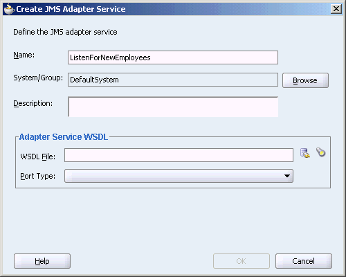
The Create JMS Adapter Service dialog box is displayed, as shown in Figure 5-37.
Specify the following information in JMS Adapter Service dialog box:
Name: Type a name for the service. In this example, type ListenForNewEmployees.
System/Group: Retain the default value.
Figure 5-38 shows the JMS Adapter Service dialog box with the Name and System/Group fields, completed.
Figure 5-38 Defining the JMS Adapter Service
Under Adapter Service WSDL, click the Configure adapter service wsdl icon.
The Adapter Configuration wizard Welcome page is displayed.
Click Next.
The Service Name dialog box is displayed with the Service Name field completed, as shown in Figure 5-39.
Retain the service name, and click Next.
The JMS Provider dialog box is displayed.
Select Oracle Enterprise Messaging Service (OEMS) as a JMS Provider, click Database from the drop-down list.
Figure 5-40 shows the JMS Provider dialog box.
Click Next.
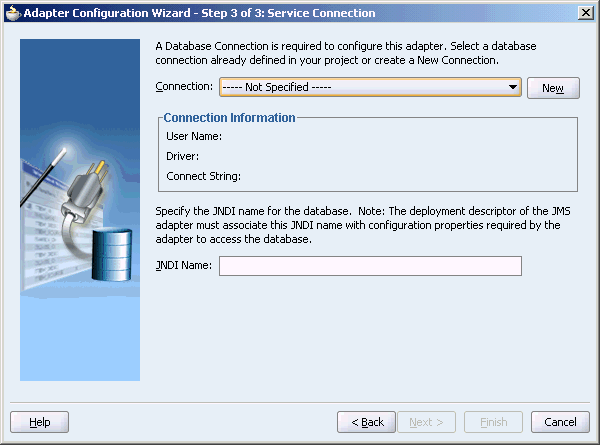
The Service Connection dialog box is displayed, as shown in Figure 5-41
Figure 5-41 The Service Connection Dialog Box
Click New to define a database connection.
The Create Database Connection Wizard Welcome page is displayed.
Click Next.
The Type dialog box is displayed.
Enter the following information in the Type dialog box:
In the Connection Name field, specify a unique name for the database connection. In this example, type OEMS.
From the Connection Type box, select Oracle (JDBC).
Figure 5-42 shows the Type dialog box.
Figure 5-42 Specifying the Connection Name and Type of Connection
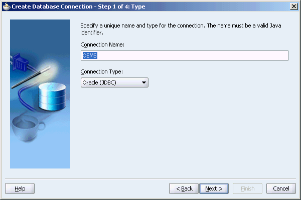
Click Next.
The Authentication dialog box is displayed.
Enter the authentication credentials in the following fields:
In the UserName field, specify a unique name for the database connection. In this example, type jmsuser.
In the Password field, specify a password for the database connection. In this example, type jmsuser.
Leave the Role field blank.
Select Deploy Password.
Figure 5-43 shows the Authentication dialog box with the credentials completed.
Figure 5-43 Specifying the Authentication Credentials
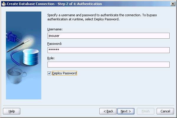
Click Next.
The Connection dialog box is displayed.
Enter information in the following fields:
In the Driver list, retain the default value, Thin.
In the Host Name field, retain the default value, localhost.
In the JDBC Port field, specify the port number for the database connection.
In the SID field, specify a unique SID value for the database connection.
Figure 5-44 shows the Connection dialog box.
Figure 5-44 Specifying the New Database Connection Information
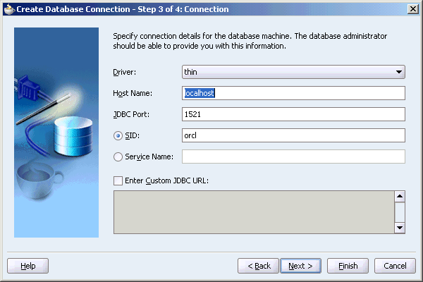
Click Next.
The Test dialog box is displayed.
Click Test Connection to determine whether the specified information establishes a connection with the database.
Click Finish to complete the process of creating a new database connection.
The Service Connection dialog box is displayed, providing a summary of the database connection.
Click Next.
The Operation dialog box is displayed.
Select Consume Message.
The Operation Name field is filled, automatically.
Figure 5-45 shows the Operation dialog box with Consume Message, selected.
Figure 5-45 Selecting an Operation for the JMS Adapter
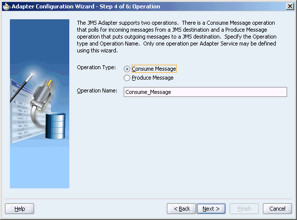
Click Next.
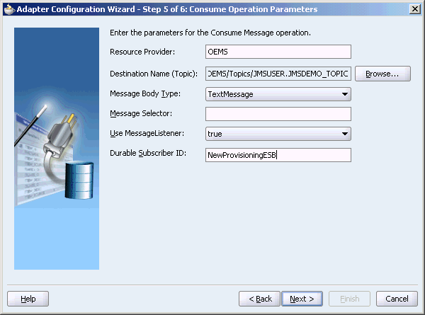
The Consume Operation Parameters dialog box is displayed.
Specify OEMS in the Resource Provider field, and click Browse for the Destination Name.
The Select Destination dialog box is displayed.
Under Destinations, click All Types, JMSUSER, select JMSDEMO_TOPIC (topic), and then click OK, as shown Figure 5-46.
The Consume Operation Parameters dialog box is displayed.
In the Durable Subscriber ID filed, type NewProvisioningESB, and then click Next.
Figure 5-47 shows the Consume Operation Parameters dialog box with all the fields, completed.
Figure 5-47 The Consume Operation Parameters Dialog Box
The Messages dialog box is displayed, as shown in Figure 5-48
Under Message Schema, next to Schema Location, click Browse.
The Type Chooser dialog box is displayed, as shown in Figure 5-49.
Click on the Import Schema File icon (top right).
The Import Schema File dialog box is displayed.
Click the Browse File System icon.
The Import Schema dialog box is displayed.
Navigate to the directory where you placed this tutorial. Select the ADDEMPLOYEES.xsd schema, as shown in Figure 5-50.
Figure 5-50 Selecting the ADDEMPLOYEES.xsd Schema
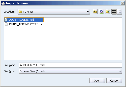
Click Open.
The Import Schema dialog box is displayed again with the URL field filled up, as shown in Figure 5-51.
Click OK. Ensure that the Add to Project checkbox is selected.
The Type Chooser dialog box, is displayed again.
In the Type Chooser dialog box, expand Imported Schemas, and then select InputParameters under ADDEMPLOYEES.xsd, as shown in Figure 5-52.
Figure 5-52 Selecting the Schema in the Type Chooser Dialog Box
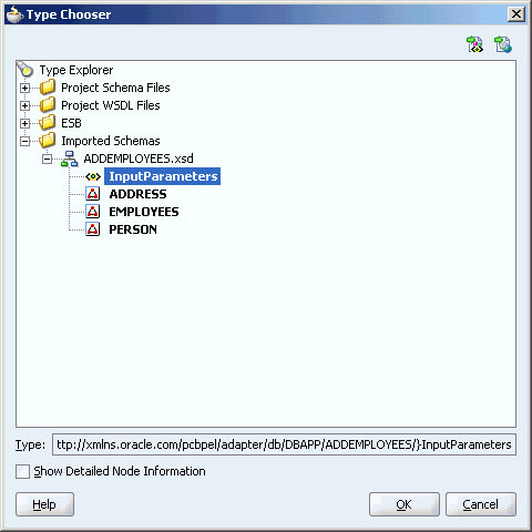
Click OK.
The Messages box is displayed with the Schema Location and Schema Element fields filled up, as shown in Figure 5-53.
Figure 5-53 The Messages Dialog Box with Schema Details Filled Up
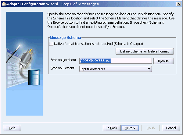
Click Next, and then click Finish.
The Create JMS Adapter Service dialog box is displayed, as shown in Figure 5-54 with all the fields filled up.
Figure 5-54 The Create JMS Adapter Dialog Box with Definitions Filled Up
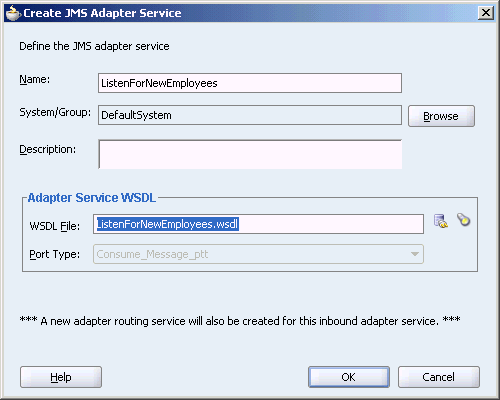
Click OK.
You have created an inbound JMS Adapter service.
Tip:
The timeout value intransaction-manager.xml must be configured to a level that is long enough for the jta transaction to complete. If you encounter an exception, increase the timeout value in transaction-manager.xml, as shown in the following example:
Caused by: javax.transaction.RollbackException: Transaction has been marked
for rollback: Timed out

at
com.evermind.server.ApplicationServerTransaction.checkMarkedForRollback(ApplicationServerTransaction.java:612)

at
com.evermind.server.ApplicationServerTransaction.enlistResource(ApplicationSer
verTransaction.java:108)

at
com.evermind.server.ApplicationServerTransaction.enlistResource(ApplicationSer
verTransaction.java:87)

at
com.evermind.server.jms.EvermindSession.checkForCMT(EvermindSession.java:1450)
Use the following steps to create an outbound DB Adapter service:
Select Adapter Services from the Component Palette, and then drag and drop Database Adapter into the NewEmployee.esb project.
The Create Database Adapter Service dialog box is displayed.
Specify the following information in Database Adapter Service dialog box:
Name: Type a name for the service. In this example, type CreateEmployee.
System/Group: Retain the default value.
Under Adapter Service WSDL, click the Configure adapter service wsdl icon.
The Adapter Configuration wizard Welcome page is displayed.
Click Next.
The Service Name dialog box is displayed with the Service Name field completed, as shown in Figure 5-55.
Retain the service name, and click Next.
The Service Connection dialog box is displayed.
Click New to define a database connection.
The Create Database Connection Wizard Welcome page is displayed.
Click Next.
The Type dialog box is displayed.
Enter the following information in the Type dialog box:
In the Connection Name field, specify a unique name for the database connection. In this example, type EmployeeDB.
From the Connection Type box, select Oracle (JDBC).
Figure 5-56 shows the Type dialog box.
Figure 5-56 Specifying the Connection Name and Type of Connection

Click Next.
The Authentication dialog box is displayed.
Enter the authentication credentials in the following fields:
In the UserName field, specify a unique name for the database connection. In this example, type dbapp.
In the Password field, specify a password for the database connection. In this example, type dbapp.
Leave the Role field blank.
Select Deploy Password.
Figure 5-57 shows the Authentication dialog box with the credentials filled up.
Figure 5-57 Specifying the Authentication Credentials
Click Next.
The Connection dialog box is displayed.
Enter information in the following fields:
In the Driver list, retain the default value, Thin.
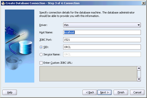
In the Host Name field, retain the default value, localhost.
In the JDBC Port field, specify the port number for the database connection.
In the SID field, specify a unique SID value for the database connection.
Figure 5-58 shows the Connection dialog box.
Figure 5-58 Specifying the New Database Connection Information

Click Next.
The Test dialog box is displayed.
Click Test Connection to determine whether the specified information establishes a connection with the database.
Click Finish to complete the process of creating a new database connection.
The Service Connection dialog box is displayed, providing a summary of the database connection, as shown in Figure 5-59.
Figure 5-59 The Service Connection Dialog Box with a Summary of the Database Connection
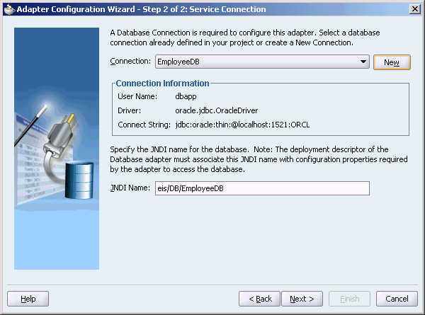
Click Next.
The Operation dialog box is displayed.
Select Call a Stored Procedure or Function as the operation type.
Figure 5-60 shows the Operation dialog box with the operation type, Call a Stored Procedure or Function selected.
Figure 5-60 Selecting an Operation for the Database Adapter
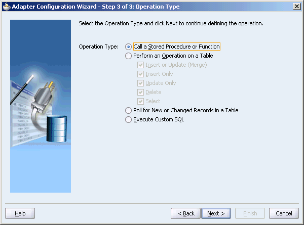
Click Next.
The Specify Stored Procedure dialog box is displayed.
For Schema, select DBAPP from the drop-down list, and then click Browse to select a procedure.
The Stored Procedures dialog box is displayed.
Select ADDEMPLOYEES under Stored Procedures from DBAPP schema, and then click OK.
Figure 5-61 shows stored procedure ADDEMPLOYEES being selected in the Stored Procedures dialog box.
Figure 5-61 The Stored Procedures Dialog Box
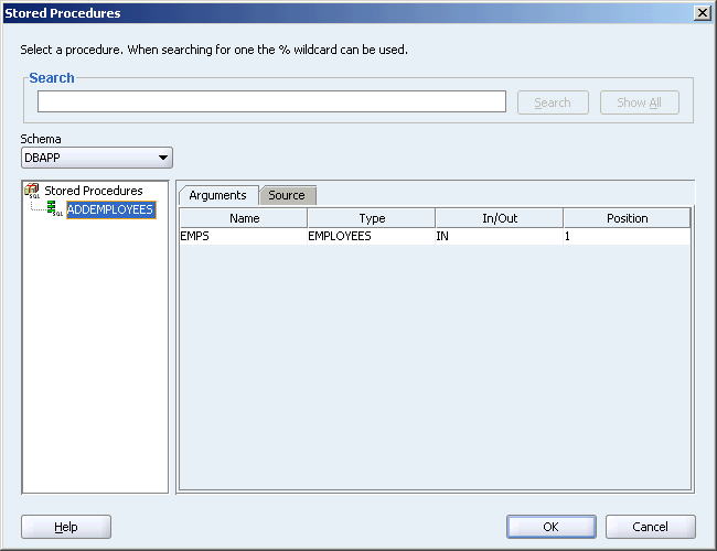
Click OK.
The Specify Stored Procedure dialog box is displayed, as shown in Figure 5-62 with a summary of the schema and stored procedure that you specified.
Figure 5-62 Specify Stored Procedure Dialog Box
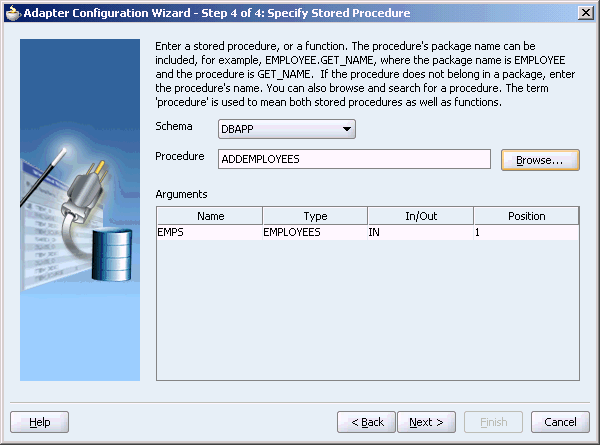
Click Next, and then click Finish.
The Create Database Adapter Service dialog box is displayed, as shown in Figure 5-63 with all the field filled up.
Figure 5-63 The Create Database Adapter Service Dialog Box
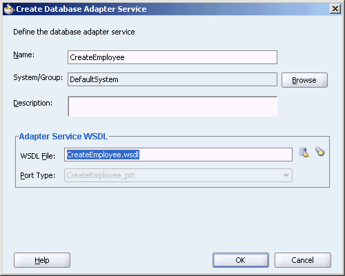
Click OK.
You have created an outbound RDBMS adapter.
The following are the steps to configure the ListenForNewEmployees routing service:
Double-click ListenForNewEmployees routing service, as shown in Figure 5-64
Figure 5-64 Selecting the Routing Service
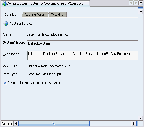
Select the Routing Rules tab, and then click on the + icon to add a rule.
The Browse Target Service Operation dialog box is displayed.
Select the CreateEmployee service, as shown in Figure 5-65.
Figure 5-65 The Browse Target Service Operation Dialog Box
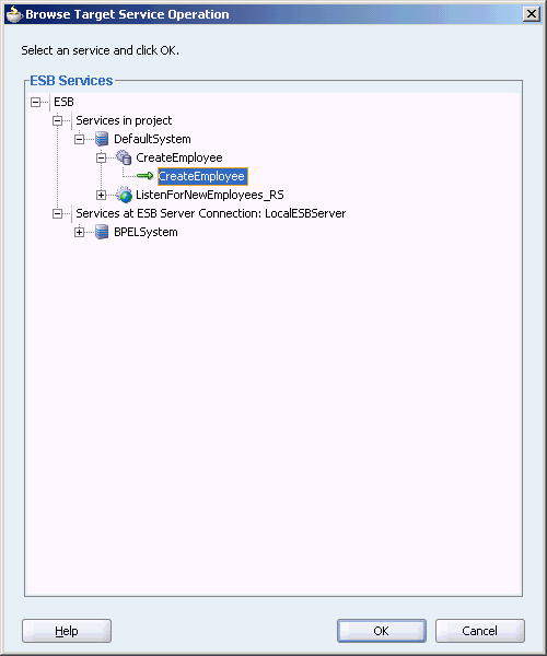
Click Ok.
The middle pane of the application window will resemble Figure 5-66.
Figure 5-66 Selecting the Transformation Map
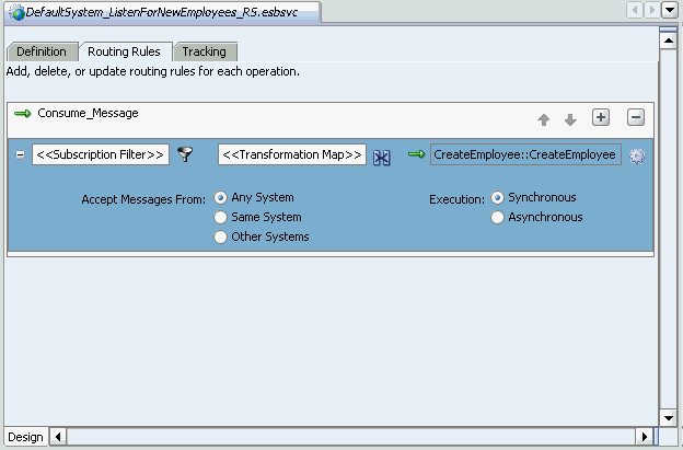
Double-click the Transformation icon, and then click the Select Create New Mapper File icon.
The Request Transformation Map dialog box is displayed, as shown in Figure 5-67.
Figure 5-67 The Request Transformation Map Dialog Box
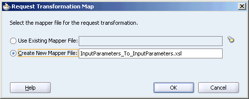
Select Create New Mapper File, accept the default name, and then click OK.
The mid pane of the application window will resemble Figure 5-68.
Select EMPS on the left-hand side of the mapper and drag it over to EMPS on the right-hand side.
The Auto Map Preferences dialog box is displayed, as shown in Figure 5-69.
Figure 5-69 The Auto Map Preferences Dialog Box
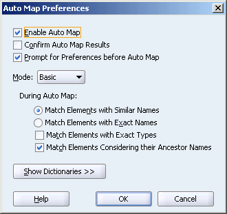
Accept the defaults map preferences, and then click OK.
The middle pane of the application window will resemble Figure 5-70.
Save and close the tab for the mapper.
Save and close the tab for the routing service.
If you deploy your services, as it is, from development to production, you will end up with your adapters pointing to your development resources, for example, EmployeeDB. A non-managed mode like this has the following issues:
Connection information is specified in the WSDL file
Default out-of-the-box (wizard captures design time connection information assuming this as runtime connection)
In order to avoid this situation, administrators should create matching data sources on the ESB server, by using any of the following managed connections.
Managed mode (Toplink)
Connection information is specified in oc4j-ra.xml through JNDI entry
This JNDI entry is referred to in the WSDL
Managed mode (OC4J)
This is the most recommended approach.
Connection information is specified in data-sources.xml
The data-source is referred by JNDI entry in oc4j-ra.xml
The JNDI entry is referred to in the WSDL
You will require the following values from the project you created:
Resource Provider: Use the value provided for resource provider in step 21 under Creating Inbound JMS Adapter in application.xml and oc4j-ra.xml.
JNDI name: Use the JNDI name specified in this example, eis/Jms/jmuser in oc4j-ra.xml.
Use the following steps to configure database resource provider in application.xml:
Navigate to the location where ESB server is installed, that is, navigate to %ESB_HOME%\ j2ee\home\config. For example:
cd D:\ORACLE\OracleESB_beta\j2ee\home\config
Open application.xml, and then add the following entry:
<resource-provider class="oracle.jms.OjmsContext" name="OEMS">
<description>Resource provider for the OEMS database</description>
<property name="url" value="jdbc:oracle:thin:jmsuser/jmsuser@localhost:1521:XE"
/>
</resource-provider>
Ensure that the database connection name matches that of the database name specified in this use case, which is, OEMS.
oc4j-ra.xmlUse the following steps to configure JMS Adapter destinations in oc4j-ra.xml:
Navigate to the JMS adapter deployment folder in the location where ESB server is installed. For example:
D:\ORACLE\OracleESB_beta\j2ee\home\application-deployments\default\JmsAdapter
Modify the JNDI name and the resource provider name in oc4j-ra.xml, as shown in the following example:
<connector-factory location="eis/Jms/OEMS" connector-name="Jms Adapter">
<config-property name="connectionFactoryLocation"
value="java:comp/resource/OEMS/TopicConnectionFactories/myTCF"/>
<config-property name="factoryProperties" value=""/>
<config-property name="acknowledgeMode" value="AUTO_ACKNOWLEDGE"/>
<config-property name="isTopic" value="trueÒ>
<config-property name="isTransacted" value="true"/>
<config-property name="username" value="jmsuser"/>
<config-property name="password" value="jmsuser"/>
<connection-pooling use="none">
</connection-pooling>
<security-config use="none">
</security-config>
</connector-factory>
Note that you have to modify the JNDI name and the resource provider name as mentioned in Configuring a JMS Adapter in Managed Mode.
oc4j-ra.xmlUse the following steps to configure JMS Adapter destinations in oc4j-ra.xml:
Navigate to the Database adapter deployment folder in the location where ESB server is installed. For example:
D:\ORACLE\OracleESB_beta\j2ee\home\application-deployments\default\DBAdapter
Modify oc4j-ra.xml, as shown in the following example:
<connector-factory location="eis/DB/EmployeeDB" connector-name="Database Adapter">
    <config-property name="xADataSourceName" value="jdbc/EmployeeDB-XA"/>
    <config-property name="dataSourceName" value="jdbc/EmployeeDB"/>
    <config-property name="platformClassName"
value="oracle.toplink.platform.database.Oracle9Platform"/>
    <config-property name="usesNativeSequencing" value="true"/>
    <config-property name="sequencePreallocationSize" value="50"/>
    <config-property name="defaultNChar" value="false"/>
    <config-property name="usesBatchWriting" value="true"/>
    <connection-pooling use="none">
    </connection-pooling>
    <security-config use="none">
    </security-config>
</connector-factory>
data-sources.xmlUse the following steps to configure JMS Adapter destinations in oc4j-ra.xml:
Navigate to the config folder in the location where ESB server is installed. For example:
D:\ORACLE\OracleESB_beta\j2ee\home\config
Modify data-sources.xml, as shown in the following example:
<managed-data-source name="EmployeeDB-XA" connection-pool-name="EmployeePool"
jndi-name="jdbc/EmployeeDB-XA"/>
<managed-data-source name="EmployeeDB" connection-pool-name="EmployeePool"
jndi-name="jdbc/EmployeeDB"/>
<connection-pool name="EmployeePool">
          <connection-factory factory-class="oracle.jdbc.pool.OracleDataSource"
user="dbapp" password="dbapp" url="jdbc:oracle:thin:@//localhost:1521/XE">
          </connection-factory>
Use the following steps to restart your ESB server after configuring resource providers:
Click Start menu, point to ESB, and then select Stop ESB.
Click Start menu, point to ESB, and then select Start ESB.
This is the final step in the design-time. Use the following steps to register with ESB:
Save All
Right-click AQJMStoDB project, select Register with ESB, and then click LocalIntegrationServer.
To check the ESB control, open the ESB Console. For example: http://localhost:8888/esb/esb/EsbConsole.html
Now, your service window will resemble Figure 5-71.
The following are the steps to send a JMS message to trigger the new service:
Open a DOS prompt and go to the tools directory, under tutorials, as shown in the following example:
cd C:\ESBSamples\AQJMStoDB\tools
Edit setenv.bat to reflect your environment (classpath) and OEMS properties to reflect your server settings (location, port, and so on). Then send a message as shown in the following example:
C:\ESBSamples\AQJMStoDB\tools>setenv
C:\ESBSamples\AQJMStoDB\tools>java send JMSDEMO_TOPIC

-------------------------------------------------------------
OEMS.155 - simple JMS send / JMS 1.02 / Database AQ / no JNDI
-------------------------------------------------------------
Connection factory = oracle.jms.AQjmsTopicConnectionFactory@ab95e6

destination: JMSUSER.JMSDEMO_TOPIC
message    :

<?xml version = '1.0' encoding = 'UTF-8'?>
<db:InputParameters
xmlns:db="http://xmlns.oracle.com/pcbpel/adapter/db/DBAPP/AD
DEMPLOYEES/">
   <EMPS>
      <EMPS_ITEM>
         <FNAME>John</FNAME>
         <MIDDLE>W</MIDDLE>
         <LNAME>Doe</LNAME>
         <ADDR>
            <STREET>100 Oracle Parkway</STREET>
            <CITY>Redwood Shores</CITY>
            <STATE>CA</STATE>
            <ZIP>94065</ZIP>
         </ADDR>
      </EMPS_ITEM>
   </EMPS>
</db:InputParameters>

message was sent with ID=ID:F85494669F764BFAB51CC75367D07B35
Use the following steps to check execution in the ESB control:
Open the ESB Console.
Click Instances on top-right corner.
Click the green arrow next to Search.
An instance resembling Figure 5-72 is displayed.