| Oracle® Application Server Adapters for Files, FTP, Databases, and Enterprise Messaging User's Guide 10g Release 3 (10.1.3.1.0) Part Number B28994-02 |
|
|
View PDF |
| Oracle® Application Server Adapters for Files, FTP, Databases, and Enterprise Messaging User's Guide 10g Release 3 (10.1.3.1.0) Part Number B28994-02 |
|
|
View PDF |
This chapter describes how to use the Oracle Application Server Adapter for MQSeries (MQSeries adapter), which works in conjunction with Oracle BPEL Process Manager and Oracle Enterprise Service Bus as an external service. It contains the following sections:
Message queuing is a technique for asynchronous program-to-program communication. It enables application integration by allowing independent applications on a distributed system to communicate with each other. One application sends messages to a queue owned by a queue manager, and another application retrieves the messages from the queue. The communication between applications is maintained even if the applications are running at different times or are temporarily unavailable.
The following list explains the basic concepts of message queuing:
Messaging is the mechanism that allows two entities to communicate by sending and receiving messages. Messaging can be of two types, synchronous and asynchronous. In synchronous messaging, sender of the message places a message on a message queue and then waits for a reply to its message before resuming its own processing. In asynchronous messaging, sender of the message proceeds with its own processing without waiting for a reply.
Messages are structured data sent by one program and intended for another program.
Message queues are objects that store messages in an application. Applications can put messages to the queues and get messages from the queues. A queue is managed by a queue manager.
A queue manager provides the messaging and queuing services to applications through an application programming interface. It provides access to the queues and also transfers messages to another queue manager through message channels.
A message channel provides a communication path between two queue managers. It connects the queue managers. A message channel can transmit messages in one direction only.
A transmission queue is used to temporarily store messages that are destined for a remote queue manager.
If a message is very large, it can be divided into multiple small messages called segments. Each segment has a group ID and an offset. All segment of a message have same group ID. The last segment of the message is marked with a flag.
A message group consists of a set of related messages with the same group ID. Each message in a message group has a message sequence number. The last message in a message group is marked with a flag.
A cluster is a group of queue managers that are logically associated.
To enqueue is to put a message in a queue whereas to dequeue is to get a message from a queue as shown in Figure 6-1.
In request/reply interaction, a program sends a message to another program asking for a reply. The request message contains information about to where the reply should be sent. The receiving program sends a reply message in response to the request message. The request/reply interaction is shown in Figure 6-2.
See Also:
Section 6.3.1.2, "Dequeue Message" for information about the interactions scenarios supported by the MQSeries adapter.Messaging and Queuing Series (MQSeries) is a set of products and standards developed by IBM. MQSeries provides a queuing infrastructure that provides guaranteed message delivery, security, and priority-based messaging.
The communication process between an MQSeries application and a MQSeries server is shown in Figure 6-3. An MQSeries client enables an application to connect to a queue manager on a remote machine.
Figure 6-3 The MQSeries Communication Process

Every queue in MQSeries belongs to a queue manager. A queue manager has a unique name and provides messaging and queuing services to applications through a Message Queue Interface (MQI) channel. A queue manager also provides access to the queues created on it and transfers messages to other queue managers through message channels.
In MQSeries, data is sent in the form of messages. The sending application constructs a message and sends it to a queue by using the API calls. The message remains in the queue until the receiving application is ready to receive it. The receiving application gets the messages from the queue by using the API calls.
For sending messages to a remote queue, the remote queue definition must be defined locally. The remote queue definition consists of the destination queue name and the transmission queue name.
Figure 6-4 displays message structure of an MQSeries message.
An MQSeries message consists of following parts, as shown in Figure 6-4:
The message header contains information such as, unique message ID, message type, message priority, and routing information. Every MQSeries message must have a message header.
The optional header is required for communication with specific applications, such as CICS application.
See Also:
Section 6.3.10, "Integration with CICS"The actual data. For example, a record from an indexed or flat file or a row or column from a DB2 table.
Oracle BPEL Process Manager and Oracle Enterprise Service Bus include the MQSeries adapter. The MQSeries adapter enables applications to connect to MQSeries queue managers and place MQSeries messages on queues or to remove MQSeries messages from queues.
This section contains the following sections:
Section 6.2.2, "MQSeries Adapter Integration with Oracle BPEL Process Manager"
Section 6.2.3, "MQSeries Adapter Integration with Oracle Enterprise Service Bus"
The MQSeries adapter provides all native MQSeries functionalities. Although you can configure the Oracle Application Server Adapter for Java Message Service (JMS adapter) with MQSeries provider, it provides only the JMS functionalities provided by MQSeries and not the native MQSeries functionalities. The following list explains the advantages of MQSeries adapter over the JMS adapter for MQSeries:
The MQSeries adapter supports Positive Action Notification (PAN)/Negative Action Notification (NAN).
The MQSeries adapter supports report messages such as, confirmation on delivery, confirmation on arrival, exception report, and expiry report.
The MQSeries adapter supports sending unwanted or corrupted message to a dead-letter queue.
The MQSeries adapter provides advanced filter options, such as filtering message belonging to a group.
The MQSeries adapter is faster and easier to use.
The MQSeries adapter is automatically integrated with Oracle BPEL Process Manager. When you create a partner link or a MQ adapter service in Oracle JDeveloper, the Adapter Configuration Wizard is started.
This wizard enables you to select and configure the MQSeries adapter or other OracleAS Adapters, as shown in Figure 1-3. The Adapter Configuration Wizard then prompts you to enter a service name, as shown in Figure 1-4. When configuration is complete, a WSDL file of the same name is created in theApplications Navigator section of Oracle JDeveloper. This WSDL file contains the configuration information you specify with the Adapter Configuration Wizard.
The Operations window of the Adapter Configuration Wizard prompts you to select an operation to perform. Based on your selection, different Adapter Configuration Wizard windows appear and prompt you for configuration information.
Table 6-1 lists the available operations and provides references to sections that describe the information about these operations.
Table 6-1 Supported Operations for Oracle BPEL Process Manager
The MQSeries adapter is automatically integrated with Oracle Enterprise Service Bus. When you create an MQ adapter service in JDeveloper ESB Designer, the Adapter Configuration Wizard is started as shown in Figure 1-2.
This wizard enables you to select and configure the MQSeries adapter. When configuration is complete, a WSDL file of the same name is created in the Applications Navigator section of Oracle JDeveloper. This WSDL file contains the configuration information you specify with the Adapter Configuration Wizard.
The Operations window of the Adapter Configuration Wizard prompts you to select an operation to perform. Based on your selection, different Adapter Configuration Wizard windows appear and prompt you for configuration information. Table 6-2 lists the available operations and provides references to sections that describe the configuration information you must provide.
Table 6-2 Supported Operations for Oracle Enterprise Service Bus
| Operation | See Section... |
|---|---|
|
Enqueue Message |
Section 6.3.1.1, "Enqueue Message" |
|
Dequeue Message |
Section 6.3.1.2, "Dequeue Message" |
|
Request-Response |
Section 6.3.1.6, "Request-Response Synchronous (Oracle Enterprise Service Bus as Server)" |
This section explains the following concepts of the MQSeries adapter:
The MQSeries adapter supports the following messaging scenarios:
Synchronous Request-Response (Oracle BPEL Process Manager as Server)
Asynchronous Request-Response (Oracle BPEL Process Manager as Server)
Request-Response Synchronous (Oracle Enterprise Service Bus as Server)
Note:
The MQSeries adapter does not support XA transactions.In this scenario, the MQSeries adapter connects to a specific queue managed by a queue manager and then writes the message to the queue. For outbound messages sent from Oracle BPEL Process Manager or Oracle Enterprise Service Bus, the MQSeries adapter performs the following operations:
Receives message from Oracle BPEL Process Manager or Oracle Enterprise Service Bus.
Formats the XML content as specified at the design time.
Sets the properties of the message such as, priority, expiry, message type, and persistence. These properties are based on the selections that you made in the Adapter Configuration wizard.
For information on message properties, see Section 6.3.2.1, "Messages Types".
Sends the message to the queue specified at design time in the Adapter Configuration wizard.
Figure 6-5 displays the operation type that you need to select in the Adapter Configuration wizard window.
Figure 6-5 Adapter Configuration Wizard: Produce Message Selection
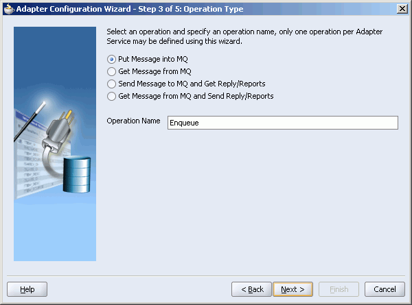
The window that appears after selecting the Put Message into MQ operation type is shown in Figure 6-6.
You can specify the following properties in this window:
Queue Name: The name of the queue on which the MQSeries adapter will enqueue the message. This is a mandatory field.
Queue Manager: The name of the queue manager to which the queue belongs. This field is optional and should be used when enqueuing message to a remote queue.
Message Format: The format of the message.
Note:
When enqueuing a message, ensure that the various mandatory values, required for a specific format, are specified correctly.Priority: The priority of the message ranging from 0 (low) to 9 (high).
Persistence: The persistence of the message. You can also specify the persistence of the message to be taken from the default priority attribute, as defined by the destination queue.
Expiry: The expiry time of the message. The message is discarded after the expiry time has elapsed.
Refer to Section 6.3.2, "Message Properties" for detailed information about these properties.
The next Adapter Configuration Wizard window that appears is the Messages window shown in Figure 6-7. This window enables you to select the XML Schema Definition (XSD) file for translation.
If native format translation is not required (for example, a JPG or GIF image is being processed), select the Native format translation is not required check box. The file is passed through in base-64 encoding.
XSD files are required for translation. If you want to define a new schema or convert an existing data type description (DTD) or COBOL Copybook, then select Define Schema for Native Format. This starts the Native Format Builder Wizard. This wizard guides you through the creation of a native schema file from file formats, such as comma-separated value (CSV), fixed-length, DTD, and COBOL Copybook. After the native schema file is created, you are returned to this Messages window with the Schema File URL and Schema Element fields filled in. See Section 7.1, "Creating Native Schema Files with the Native Format Builder Wizard" for more information.
In this scenario, the MQSeries adapter connects to a specific queue managed by a queue manager and then removes the message from the queue. For inbound messages sent to Oracle BPEL Process Manager or Oracle Enterprise Service Bus, the MQSeries adapter performs the following operations:
Connects to the queue specified at the design time.
Dequeues the message from the queue when a message arrives.
Reads and translates the message based on the translation logic defined at design time.
Publishes the message as XML message to Oracle BPEL Process Manager or Oracle Enterprise Service Bus.
Figure 6-8 displays the operation type that you need to select in the Adapter Configuration wizard.
Figure 6-8 Adapter Configuration Wizard: Consume Message Selection
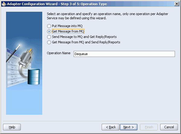
The window that appears after selecting the Get Message into MQ operation type is shown in Figure 6-6.
You can specify the following properties in this window:
Queue Name: The name of the queue from which the MQSeries adapter will dequeue the message. This is a mandatory field.
Queue Manager: The name of the queue manager to which the queue belongs. This field is optional.
The next Adapter Configuration Wizard window that appears is the Messages window shown in Figure 6-7. This window enables you to select the XSD schema file for translation.
As with specifying the schema for the produce message operation, you can perform the following tasks in this window:
Specify if native format translation is not required
Select the XSD schema file for translation
Start the Native Format Builder Wizard to create an XSD file from file formats such as CSV, fixed-length, DTD, and COBOL Copybook
See Section 6.3.1.1, "Enqueue Message" for more information about the Messages window.
In this scenario, the Oracle BPEL Process Manager sends a request message and receives the corresponding response using a non-initiating receive activity. The invoke activity initiates the outbound invocation of the adapter to send the request. The MQSeries adapter performs the following operations:
Receives message from Oracle BPEL Process Manager.
Formats the XML content as specified at the design time in the Adapter Configuration wizard.
Sets properties and a correlation schema on the request message.
Sends the message to the queue specified at the design time. The third-party application receives the message, processes it, generates the response, and then enqueus the response message to the replyTo queue specified in the request message. The Correlation ID and Message ID of the response message is generated on the basis of the correlation schema specified in the request message.
The MQSeries adapter dequeues the message from the queue.
Sends the response to the non-initiating receive activity of the BPEL process. To ensure that response is sent to correct BPEL instance, correlation schemas are used.
Figure 6-10 shows a sample BPEL process for this scenario.
Figure 6-10 Oracle BPEL Process Manager as Client Sample
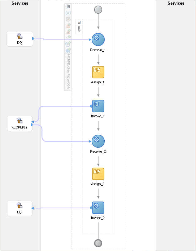
Figure 6-11 displays the operation type that you need to select in the Adapter Configuration wizard.
The window that appears after selecting the Send Message to MQ and Get Reply/Reports operation type is shown in Figure 6-12.
Figure 6-12 Send Message to MQ and Get Reply/Reports Window
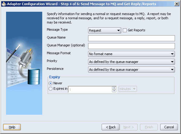
You can specify the following properties in this window:
Message Type: The type of the message. You can send a normal message or a request message.
Get Reports: Select this option if you want any kind of report. You can specify the type of report in the next window shown in Figure 6-13.
Queue Name: The name of the queue to which the MQSeries adapter enqueues the message. This is a mandatory field.
Queue Manager: The name of the queue manager to which the queue belongs. This field is optional.
Message Format: The format of the message.
Priority: The priority of the message ranging from 0 (low) to 9 (high).
Persistence: The persistence of the message.
Expiry: The expiry time of the message. The message is discarded after the expiry time has elapsed.
Refer to Section 6.3.2, "Message Properties" and Section 6.3.5, "Report Messages" for more information about these properties.
The window that is displayed when you click Next in the Send Message to MQ and Get Reply/Reports window can be a Reports window (shown in Figure 6-13) or a Response window (shown in Figure 6-13).
The Reports window shown in Figure 6-13 is displayed only if you have selected the Get Reports option in the Send Message to MQ and Get Reply/Reports window shown in Figure 6-12.
You can select the following types of reports in this window:
Confirmation on Arrival
Confirmation on Delivery
Exception Report
Expiry Report
Refer to Section 6.3.5, "Report Messages" for information about these report types.
The Response window shown in Figure 6-14 is displayed when you click Next in the Reports window.
You can specify the following properties in the Response window:
Queue Name: The name of the queue to which the response should be sent. This is a mandatory field.
Queue Manager: The name of the queue manager to which the queue belongs. This field is optional.
Correlation Schema: The correlation schema that should be used by the MQSeries adapter. For information about correlation schemas, refer toSection 6.3.3, "Correlation Schemas" .
When you click Next in the Response window, a Messages window shown in Figure 6-15 is displayed. This window enables you to select the XSD schema file for translation for request as well as response message.
You can perform the following tasks in this window:
Specify if native format translation is not required
Select the XSD schema file for translation
Start the Native Format Builder Wizard to create an XSD file from file formats such as CSV, fixed-length, DTD, and COBOL Copybook
See Section 6.3.1.1, "Enqueue Message" for more information about the Messages window.
In this scenario, the Oracle BPEL Process Manager receives a request, processes it, and sends the response synchronously by using a reply activity. The MQSeries adapter performs the following operations:
Dequeues the request message from the queue when the message arrives.
Reads and translates the message based on the translation logic defined at design time.
Publishes the message as XML message to Oracle BPEL Process Manager. The Oracle BPEL Process Manager processes the request and sends the response to the MQSeries adapter.
Receives the response message from the Oracle BPEL Process Manager.
Formats the XML content as specified at the design time.
Sets the properties of the message such as priority, expiry, message type, and persistence. These properties are based on the selections that you made in the Adapter Configuration wizard.
Sends the message to the queue specified at design time in the Adapter Configuration wizard.
Figure 6-16 shows a sample BPEL process for this scenario.
Figure 6-16 Synchronous Request-Response Oracle BPEL Process Manager as Server sample
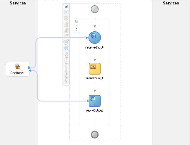
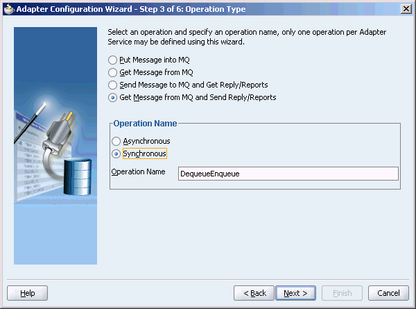
Figure 6-17 displays the operation type that you need to select in the Adapter Configuration wizard.
Figure 6-17 Operation Type Window Selection for Request-Response Synchronous Interaction
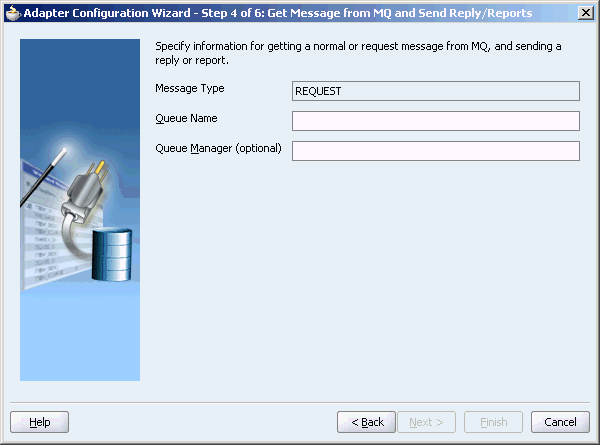
The window that appears after selecting the Get Message from MQ and send Reply/Reports operation type is shown in Figure 6-18. Specify the queue name from which the MQSeries adapter will dequeue the message in this window.
Figure 6-18 Get Message from MQ and Send Reply/Reports Window
When you click Next in the Get Message from MQ and send Reply/Reports window, the Response window shown in Figure 6-19 is displayed.
Figure 6-19 Response Window for Synchronous Request-Response
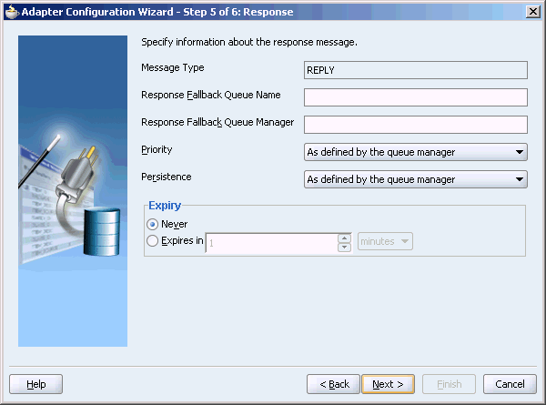
You can specify the following properties in the Response window:
Response Fallback Queue Name: The queue to which the response should be sent for a normal message.
Note:
The Response fallback queue should be the primary queue of its queue manager.Response Fallback Queue Manager: The name of the queue manger to which the response fallback queue belongs.
Priority: The priority of the message.
Persistence: The persistence of the message.
Expiry: The expiry time of the message.
Refer to Section 6.3.2, "Message Properties" for more information about these properties.
On clicking Next in the Response window, the Messages window shown in Figure 6-15 is displayed. You can perform the following tasks in this window:
Specify if native format translation is not required
Select the XSD schema file for translation
Start the Native Format Builder Wizard to create an XSD file from file formats such as CSV, fixed-length, DTD, and COBOL Copybook
See Section 6.3.1.1, "Enqueue Message" for more information about the Messages window.
In Oracle BPEL Process Manager initiated request-response interaction, a BPEL process receives a request as an inbound message, processes it, and then sends the response through an invoke activity. For asynchronous request-reply scenario, the MQSeries adapter performs the following operations:
Dequeues the message from the queue when a message arrives.
Reads and translates the message based on the translation logic defined at design time.
Publishes the message as XML message to Oracle BPEL Process Manager. The Oracle BPEL Process Manager processes the request and sends the response to the MQSeries adapter.
Receives messages from Oracle BPEL Process Manager.
Formats the XML content as specified at design time.
Sets the properties of the message, such as priority, expiry, message type, and persistence. These properties are based on the selections that you made in the Adapter Configuration wizard.
Sends the message to the queue specified at design time in the Adapter Configuration wizard.
Figure 6-20 shows a sample BPEL process for this scenario.
Figure 6-20 Asynchronous Request-Response Oracle BPEL Process Managerr as Server sample
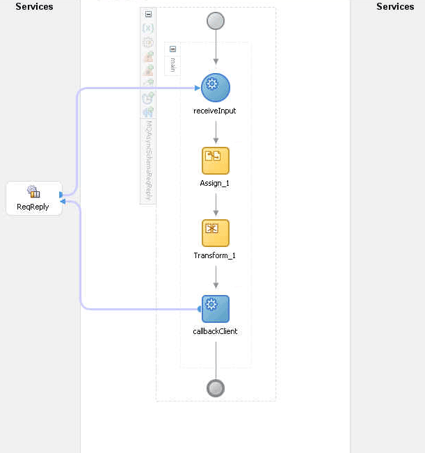
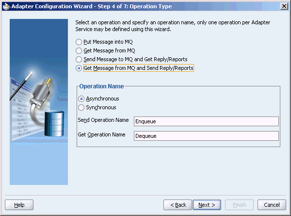
Figure 6-21 displays the operation type that you need to select in the Adapter Configuration wizard.
Figure 6-21 Operation Type Window Selection for Request-Response Asynchronous Interaction
The window that appears after selecting the Get Message from MQ and send Reply/Reports operation type is shown in Figure 6-18. Specify the queue name from which the MQSeries adapter will dequeue the message in this window.
When you click Next in the Get Message from MQ and send Reply/Reports window, the Response window shown in Figure 6-19 is displayed.
You can specify the following properties in the Response window:
Response Fallback Queue Name: The queue to which the reply should be sent if the replyto queue is not specified in the request message.
Response Fallback Queue Manager: The name of the queue manger to which the response fallback queue belongs.
Priority: The priority of the message.
Persistence: The persistence of the message.
Expiry: The expiry time of the message.
Refer to Section 6.3.2, "Message Properties" for more information about these properties.
On clicking Next in the Response window, the Messages window shown in Figure 6-15 is displayed. You can perform the following tasks in this window:
Specify if native format translation is not required
Select the XSD schema file for translation
Start the Native Format Builder Wizard to create an XSD file from file formats such as CSV, fixed-length, DTD, and COBOL Copybook
See Section 6.3.1.1, "Enqueue Message" for more information about the Messages window.
In asynchronous request-reply interaction, you must map the following properties from the inbound message header to the outbound message header:
MsgID
CorrelID
CorrelationScheme
ReplyToQ
You can use the Assign activity to map these properties.
In this scenario, the Oracle Enterprise Service Bus receives a request, processes it, and sends the response synchronously. The MQSeries adapter performs the following operations:
Dequeues the request message from the queue when the message arrives.
Reads and translates the message based on the translation logic defined at design time.
Publishes the message as XML message to Oracle Enterprise Service Bus. The Oracle Enterprise Service Bus processes the request and sends the response to the MQSeries adapter.
Receives the response message from the Oracle Enterprise Service Bus.
Formats the XML content as specified at the design time.
Sets the properties of the message such as priority, expiry, message type, and persistence. These properties are based on the selections that you made in the Adapter Configuration wizard.
Sends the message to the queue specified at design time in the Adapter Configuration wizard.
Figure 6-22 displays the operation type that you must select in the Adapter Configuration wizard.
Figure 6-22 Oracle Enterprise Service Bus as Server-Request-Response Synchronous Interaction
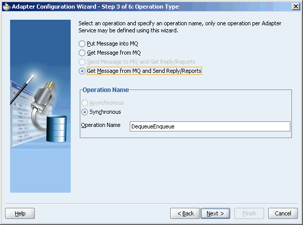
From this window onwards, all the window are similar to the windows explained in Section 6.3.1.4, "Synchronous Request-Response (Oracle BPEL Process Manager as Server)" .
The MQSeries adapter supports the following message properties:
The MQSeries adapter supports the following four types of messages:
A normal message is sent by one program to another program without expecting any response.
A request message is sent by one program to another program requesting for a response.
A reply message is sent by a program in response to a request message.
A report message is sent by receiving program to sending program as confirmation of successful or unsuccessful delivery of a message. A report message can be generated for any of the message types, normal message, request message, or reply message.
For information on acknowledgment messages supported by the MQSeries adapter, refer to Section 6.3.5, "Report Messages".
You can specify the format of an for an outgoing message through Adapter Configuration wizard, as shown in Figure 6-6. Following message formats are supported:
No format name (Default)
Command server request/reply message
Type 1 command reply message
Type 2 command reply message
Dead-letter header
Event message
User-defined message in programmable command format
Message consisting entirely of characters
Trigger message
Transmission queue header
You can specify the expiry time for an outgoing message Adapter Configuration wizard shown in Figure 6-6. The queue manager discards the message after the expiry time of a message has elapsed.
If a message has expiration notification set, then a notification is generated when the message is discarded. The notification is sent to the queue specified in the replyToQueue parameter. By default, NEVER is set for the expiry field.
You can specify the priority of an outgoing message through Adapter Configuration wizard, as shown in Figure 6-6. A priority can be in the range of 0 (low) to 9 (high). You can also specify the priority of the message to be taken from the default priority attribute, as defined by the destination queue. By default, AS_Q_DEF is set as message priority.
You can specify the persistence of an outgoing message through Adapter Configuration wizard shown in Figure 6-6. If message persistence is not set, a message is lost when the queue manager restarts or there is a system failure. If you set persistence for a message to true, it means that the message will not be lost even if there is system failure or the queue manager is restarted. You can also specify the persistence of the message to be taken from the default priority attribute, as defined by the destination queue. Persistent messages are written to log files and queue data files. If a queue manager is restarted after a failure, it recovers these persistent messages from these files.
Note:
You can specify all these message properties at run time through message headers. You can use the assign activity to assign values to these properties.Correlation is required for mapping a response to a request in a request-reply interaction. Each MQSeries request message contains a message ID and a correlation ID. When an application receives a request message from Oracle BPEL Process Manager, it checks for the correlation schema defined for the response message. Based on the correlation schema, the application generates the message ID and correlation ID of the response message.
The response window of the Adapter Configuration wizard shown in Figure 6-23 enables you to specify the correlation schema for the response message.
Figure 6-23 Selecting Correlation Schemas
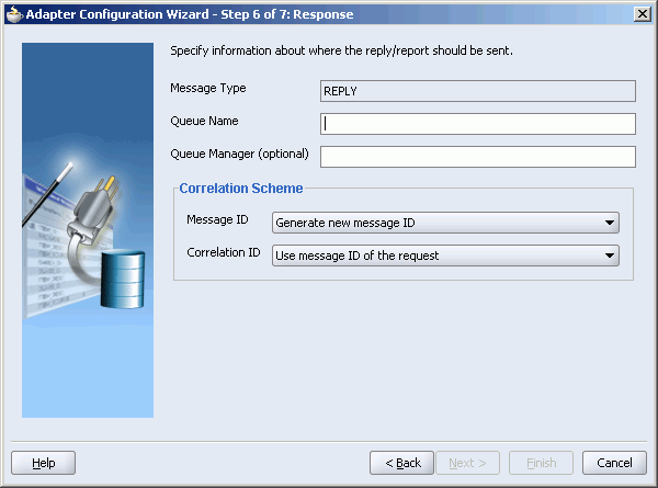
The Message ID box shown in Figure 6-23 provides the following options for the message ID of the response message:
Generate a new message ID for the response message
Use the message ID of the request message
Similarly, the Correlation ID box shown in Figure 6-23 provides the following options for the correlation ID of the response message:
Use the message ID of the request message
Use the correlation ID of the request message
The MQSeries adapter enables you to enqueue a message to multiple queues. You can use the DisributionList parameter of the adapter WSDL file for this. For example:
DistributionList="Queue1Name,QueueManger1Name; Queue2Name,QueueManger2Name"
The queue name and queue manager name value pairs should be separated by semi colon (;). The queue manager name is optional.
The MQSeries adapter enables you to set various types of acknowlegement messages on an outgoing message. These acknowlegement messages are known as report messages. A report message is generated only if the criteria for generating that report message is met. When enqueuing a message on a queue, you can request for more than one type of report message. When you request for a report message, you must specify the queue name to which the report message will be sent. This queue is known as replyTo queue. A report message can be generated by a queue manager, a message channel, or an application.
The MQSeries adapter supports the following message reports:
The Confirmation on Arrival (COA) message indicates that the message has been delivered to the target queue manager. A COA message is generated by the queue manager. This message report can be selected in the Reports window of the Adapter Configuration window shown in Figure 6-13.
A Confirmation on Delivery (COD) message indicates that the message has been retrieved by the receiving application. A COD message is generated by the queue manager. This message report can be selected in the Reports window shown in Figure 6-13.
An exception report is generated when a message cannot be delivered to the specified destination queue. Exception reports are generated by the message channel. This message report can be selected in the Reports window of the Adapter Configuration window shown in Figure 6-13.
An expiry report indicates that the message was discarded because the expiry time specified for the message elapsed before the message could be delivered. An expiry report is generated by a queue manager. This message report can be selected in the Reports window of the Adapter Configuration window shown in Figure 6-13.
A Positive Action Notification (PAN) indicates that a request has been successfully processed. It means that the action requested in the message has been performed successfully. This type of report is generated by the application.
A Negative Action Notification (NAN) indicates that a request has not been successfully serviced. It means that the action requested in the message has not been performed successfully. This type of report is generated by the application.
You can specify whether all these report messages except PAN and NAN should contain the complete original message, a part of the original message, or no part of the original message. You can select one of the following options in the Adapter Configuration wizard:
No data from the original message
The first 100 bytes of data in original message
The entire original message
The MQSeries adapter enables you to filter the messages by priority in the inbound interaction. When you specify a priority in the FilterByPriority parameter, the MQSeries adapter checks the queue for the messages that have same priority, as specified in the FilterByPriority parameter. The following example shows how to set the FilterByPriority parameter:
FilterByPriority= "2"
The MQSeries adapter enables you to specify the action that should be taken in case a message could not be delivered to the destination queue. You can specify one of the following actions:
Place message on a dead-letter queue
This is the default action. Message is placed on a dead-letter queue if it cannot be delivered to the destination queue. A report message is generated if requested by the sender. Specify DeadLetterQueue as value of the OnDeliverFailure parameter in the adapter WSDL file as shown in the following example:
OnDeliverFailure="DeadLetterQueue"
Discard message
This indicates that the message should be discarded if it cannot be delivered to the destination queue. A report message is generated, if requested by the sender. Specify Discard as value of the OnDeliverFailure parameter in the adapter WSDL file as shown in the following example:
OnDeliverFailure="Discard"
The MQSeries adapter supports message segmentation for both inbound and outbound interactions. Segmentation is required when size of a message is greater than the message size specified in the queue manager. A physical message is divided into two or more logical messages. All logical messages have same group ID and a sequence number, and an offset.
In the inbound interaction, the segmentation is inherently supported by the MQSeries adapter. The MQSeries adapter dequeues all logical messages in the order of sequence number and then publishes the single message as XML to Oracle BPEL Process Manager or Oracle Enterprise Service Bus.
In the outbound interaction, you can set the SegmentIfRequired parameter to segment the outgoing message, if required. For example:
SegmentIfRequired="true"
The message will be segmented based on constraints such as, if the size of the message is larger than the maximum limit set on the queue.
The MQSeries adapter supports message grouping for both inbound and outbound interactions. Messages belonging to a group can be complete messages or logical segments of a physical message.
In the inbound interaction, grouping is inherently supported by the MQSeries adapter. The MQSeries adapter dequeues all the messages that belong to same group or that have same group ID in the order of sequence number and publishes the single message as XML to Oracle BPEL Process Manager or Oracle Enterprise Service Bus.
Note:
Message grouping is not supported when the inbound messages have an opaque schema.In the outbound interaction, grouping is supported through headers. You have to generate same group ID for all messages and also specify the sequence number. The message in the group should be marked with last-msg-in-group flag. In Oracle BPEL Process Manager, you can use the assign activity to set these properties. For example, you want to send three messages as part of the same group:
For the first message, set the following properties through Assign activity:
IsMsgInGroup: This property should be set to true.
GroupId: A group id can be generated by the queue manager or you can specify your own group id. If you want to the queue manager to generate the group id, set the GroupId as GENERATE_GROUP_ID.
MsgSeqNumber: This property should be set to 1.
IsLastMsgInGroup: This property should be set to false.
Figure 6-24 shows the assign activity dialog box:
For the second message, first copy the GroupId of the first message from the message header to the second message header, as shown in Figure 6-25 .
Next, set the following properties through Assign activity:
IsMsgInGroup: This property should be set to true.
MsgSeqNumber: This property should be set to 2.
IsLastMsgInGroup: This property should be set to false.
For the last message, you again need to assign the Groupid similar to the first and second message and then specify the following properties:
IsMsgInGroup: This property should be set to true.
MsgSeqNumber: This property should be set to 3.
IsLastMsgInGroup: This property should be set to true.
The MQSeries adapter provides support for sending and receiving messages from CICS server. In the inbound direction, an inbound message from CICS server is dequeued in same way as a normal message. In outbound direction, the message should be in the CICS format. A sample schema file for outbound CICS message format is shown in the following example:
<?xml version="1.0" ?><schema xmlns="http://www.w3.org/2001/XMLSchema"
        targetNamespace="http://xmlns.oracle.com/pcbpel/nxsd/cics_mqcih"
        elementFormDefault="qualified"
        attributeFormDefault="unqualified"

        xmlns:nxsd="http://xmlns.oracle.com/pcbpel/nxsd"
        nxsd:version="NXSD"

        nxsd:encoding="UTF8"
        nxsd:stream="bytes"
        nxsd:byteOrder="bigEndian"

        xmlns:nxsd_extn="http://xmlns.oracle.com/pcbpel/nxsd/extensions"

<element name="MSGForMQCICSBridge">
    <complexType>
      <sequence>
        <element name="MQCIH">
          <complexType>
            <sequence>
              <!--
              MQCHAR4   StrucId;
              Structure identifier
              -->
              <element name="StrucId" type="string"
               nxsd:style="fixedLength" nxsd:length="4" nxsd:padStyle="tail"/>

              <!--
              MQLONG    Version;
              Structure version number 1 or 2
              -->
              <element name="Version" type="string"
               nxsd:style="integer" nxsd_extn:octet="4"
               nxsd_extn:align="0" nxsd_extn:sign="unticked" />
              <!--
              MQLONG    StrucLength;
              Length of MQCIH structure V1=164 V2=180
              -->
              <element name="StrucLength" type="string"
               nxsd:style="integer" nxsd_extn:octet="4"
               nxsd_extn:align="0" nxsd_extn:sign="unticked" />

              <!--
              MQLONG    Encoding;
              Reserved
              -->
              <element name="Encoding" type="string"
               nxsd:style="integer" nxsd_extn:octet="4"
               nxsd_extn:align="0" nxsd_extn:sign="unticked" />

              <!--
              MQLONG    CodedCharSetId;
              Reserved              -->
              <element name="CodedCharSetId" type="string"
               nxsd:style="integer" nxsd_extn:octet="4" nxsd_extn:align="0"
               nxsd_extn:sign="unticked" />

              <!--
              MQCHAR8   Format;
              MQ Format name
              -->
              <element name="Format" type="string"
              nxsd:style="fixedLength" nxsd:length="8" />

              <!--
              MQLONG    Flags;
              Reserved
              -->
              <element name="Flags" type="string"
               nxsd:style="integer" nxsd_extn:octet="4" nxsd_extn:align="0"

               nxsd_extn:sign="unticked" />

              <!--
              MQLONG   ReturnCode;
              Return code from bridge
              -->
              <element name="ReturnCode" type="string"
               nxsd:style="integer" nxsd_extn:octet="4" nxsd_extn:align="0"
               nxsd_extn:sign="unticked" />

              <!--
              MQLONG   CompCode;
              MQ completion code or CICS EIBRESP
              -->
              <element name="CompCode" type="string"
               nxsd:style="integer" nxsd_extn:octet="4" nxsd_extn:align="0"
               nxsd_extn:sign="unticked" />

              <!--
              MQLONG   Reason;
              MQ reason or feedback code, or CICS EIBRESP2
              -->
              <element name="Reason" type="string"
               nxsd:style="integer" nxsd_extn:octet="4" nxsd_extn:align="0"
               nxsd_extn:sign="unticked" />

              <!--
              MQLONG   UOWControl;
              Unit-of-work control
              -->
              <element name="UOWControl" type="string"
               nxsd:style="integer" nxsd_extn:octet="4" nxsd_extn:align="0"
               nxsd_extn:sign="unticked" />

              <!--
              MQLONG   GetWaitInterval;
              Wait interval for MQGET call issued by bridge
              -->
              <element name="GetWaitInterval" type="string"
               nxsd:style="integer" nxsd_extn:octet="4" nxsd_extn:align="0"
               nxsd_extn:sign="ticked" />

              <!--
              MQLONG   LinkType;
              Link type
              -->
              <element name="LinkType" type="string"
               nxsd:style="integer" nxsd_extn:octet="4" nxsd_extn:align="0"
              nxsd_extn:sign="unticked" />

              <!--
              MQLONG   OutputDataLength;
              Output commarea data length
              -->
              <element name="OutputDataLength" type="string"
               nxsd:style="integer" nxsd_extn:octet="4" nxsd_extn:align="0"
               nxsd_extn:sign="ticked" />

              <!--
              MQLONG   FacilityKeepTime;
              Bridge facility release time
              -->
              <element name="FacilityKeepTime" type="string"
               nxsd:style="integer" nxsd_extn:octet="4" nxsd_extn:align="0"
               nxsd_extn:sign="unticked" />

              <!--
              MQLONG   ADSDescriptor;
              Send/receive ADS descriptor
              -->
              <element name="ADSDescriptor" type="string"
               nxsd:style="integer" nxsd_extn:octet="4" nxsd_extn:align="0"
               nxsd_extn:sign="unticked" />

              <!--
              MQLONG   ConversationalTask;
              Whether task can be conversational
              -->
              <element name="ConversationalTask" type="string"
               nxsd:style="integer" nxsd_extn:octet="4" nxsd_extn:align="0"
               nxsd_extn:sign="unticked" />
                            <!--
              MQLONG   TaskEndStatus;
              Status at end of task
              -->
              <element name="TaskEndStatus" type="string"
               nxsd:style="integer" nxsd_extn:octet="4" nxsd_extn:align="0"
               nxsd_extn:sign="unticked" />


              <!--
              MQBYTE   Facility[8];
              BVT token value. Initialise as required.
              -->
              <element name="Facility" type="string"
               nxsd:style="integer" nxsd_extn:octet="8" nxsd_extn:align="0"
               nxsd _extn:sign="unticked" />

              <!--
              MQCHAR4  Function;
              MQ call name or CICS EIBFN function name
              -->
              <element name="Function" type="string"
               nxsd:style="fixedLength" nxsd:length="4" />

              <!--
              MQCHAR4  AbendCode;
              Abend code
              -->
              <element name="AbendCode" type="string"
               nxsd:style="fixedLength" nxsd:length="4" />

              <!--
              MQCHAR8  Authenticator;
              Password or passticket
              -->
              <element name="Authenticator" type="string"
              nxsd:style="fixedLength" nxsd:length="8" />

              <!--
              MQCHAR8  Reserved1;
              Reserved
              -->
              <element name="Reserved1" type="string"
               nxsd:style="fixedLength" nxsd:length="8" />

              <!--
              MQCHAR8  ReplyToFormat;
              MQ format name of reply message
              -->
              <element name="ReplyToFormat" type="string"
               nxsd:style="fixedLength" nxsd:length="8" />

              <!--
              MQCHAR4  RemoteSysId;
              Remote sysid to use
              -->
              <element name="RemoteSysId" type="string"
              nxsd:style="fixedLength" nxsd:length="4" />

              <!--
              MQCHAR4  RemoteTransId;
              Remote transid to attach
              -->
              <element name="RemoteTransId" type="string"
               nxsd:style="fixedLength" nxsd:length="4" />

              <!--
              MQCHAR4  TransactionId;
              Transaction to attach
              -->
              <element name="TransactionId" type="string"
               nxsd:style="fixedLength" nxsd:length="4" />

              <!--
              MQCHAR4  FacilityLike;
              Terminal emulated attributes
              -->
              <element name="FacilityLike" type="string"
               nxsd:style="fixedLength" nxsd:length="4" />

              <!--
              MQCHAR4  AttentionId;
              AID key
              -->
              <element name="AttentionId" type="string"
               nxsd:style="fixedLength" nxsd:length="4" />

              <!--
              MQCHAR4  StartCode;
              Transaction start code
              -->
              <element name="StartCode" type="string"
              nxsd:style="fixedLength" nxsd:length="4" />

              <!--
              MQCHAR4  CancelCode;
              Abend transaction code
              -->
              <element name="CancelCode" type="string"
               nxsd:style="fixedLength" nxsd:length="4" />

              <!--
              MQCHAR4  NextTransactionId;
              Next transaction to attach
              -->
              <element name="NextTransactionId" type="string"
              nxsd:style="fixedLength" nxsd:length="4" />

              <!--
              MQCHAR8  Reserved2;
              Reserved
              -->
              <element name="Reserved2" type="string"
              nxsd:style="fixedLength" nxsd:length="8" />
              <!--
              MQCHAR8  Reserved3;
              Reserved
              -->
              <element name="Reserved3" type="string"
              nxsd:style="fixedLength" nxsd:length="8" />

              <!--
              MQLONG   CursorPosition;
              Cursor position
              -->
              <element name="CursorPosition" type="string"
              nxsd:style="integer" nxsd_extn:octet="4" nxsd_extn:align="0"
              nxsd_extn:sign="unticked" />

              <!--
              MQLONG   ErrorOffset;
              Error offset
              -->
              <element name="ErrorOffset" type="string"
               nxsd:style="integer" nxsd_extn:octet="4" nxsd_extn:align="0"
               nxsd_extn:sign="unticked" />

              <!--
              MQLONG   InputItem;
              Input item
              -->
              <element name="InputItem" type="string"
               nxsd:style="integer" nxsd_extn:octet="4" nxsd_extn:align="0"
               nxsd_extn:sign="unticked" />

              <!--
              MQLONG   Reserved4;
              Reserved
              -->
              <element name="Reserved4" type="string"
              nxsd:style="integer" nxsd_extn:octet="4" nxsd_extn:align="0"
              nxsd_extn:sign="unticked" />
            </sequence>
          </complexType>
        </element>

        <!--
        Application data
        -->
        <element name="ApplicationData" type="string"
                                      fixed="Nothing" />

      </sequence>
    </complexType>
  </element>
</schema>
The setup prerequisite for using the MQSeries adapter are:
IBM Websphere MQ server should be installed and running.
A queue manager, queue, and channel should be created.
To configure the MQSeries adapter, perform the following:
The steps in this section should be performed only once, before using the MQSeries adapter. Perform the following steps to add the com.ibm.mq.jar to the classpath for the MQSeries adapter:
Copy the com.ibm.mq.jar file to the any folder.
Create a new shared library in the server.xml file by specifying the path of the com.ibm.mq.jar as shown in the following example:
<shared-library name="oracle.mqseries" version="10.1.3">
     <code-source path="C:\ORAHOME\bpel/lib/com.ibm.mq.jar"/>
</shared-library>
The location of the server.xml file depends on your installation type. Table 6-3 lists the installation type and corresponding server.xml file location.
Table 6-3 server.xml File Location
| Installation Type | File Location |
|---|---|
|
SOA Basic Installation |
|
|
Oracle Enterprise Service Bus on Oracle Application Server Middle tier |
|
|
Oracle BPEL Process Manager on Oracle Application Server Middle tier |
|
Modify the oc4j-ra.xml file to include the new shared library as shown in the following example.
<imported-shared-libraries>
  <import-shared-library name="oracle.bpel.common"/>
  <import-shared-library name="oracle.xml"/>
  <import-shared-library name="oracle.mqseries"/>
</imported-shared-libraries>
The location of the oc4j-ra.xml file depends on your installation type. Table 6-4 lists the installation type and corresponding oc4j-ra.xml file location.
Table 6-4 oc4j-ra.xml File Location
| Installation Type | File Location |
|---|---|
|
SOA Basic Installation |
|
|
Oracle Enterprise Service Bus on Oracle Application Server Middle tier |
|
|
Oracle BPEL Process Manager on Oracle Application Server Middle tier |
|
Restart the server.
Specify the value of the following parameters in the oc4j-ra.xml file:
hostName: The name of the computer on which the IBM Websphere MQ server is running.
portNumber: The port number for connecting to the IBM Websphere MQ server.
userID: The user ID if connecting to IBM Websphere MQ server. running on a remote location.
clientEncoding: This parameter is required if you are encoding the message header.
hostOSType: This parameter should be specified if the Websphere server is running on a zSeries/Operating System (z/OS). The value should be zos.
Note:
Properties of the MQSeries queues should be set as specified in the following list:The shareability property of MQSeries queues should be set to Shareable.
Index type of the MQSeries queues should be set to MQIT_MSG_ID.
A sample oc4j-ra.xml file is shown in the following example:
<connector-factory location="eis/MQ/MQSeriesAdapter" connector-name="MQSeriesAdapter">
    <config-property name="hostName" value="localhost"/>
    <config-property name="portNumber" value="1414"/>
    <config-property name="queueManagerName" value="QM"/>
    <config-property name="channelName" value="MYCHANNEL"/>
    <config-property name="userID" value=""/>
    <config-property name="password" value=""/>
    <config-property name="clientEncoding" value=""/>
    <config-property name="hostOSType" value=""/>
    <connection-pooling use="private">
       <property name="waitTimeout" value="300" />
       <property name="scheme" value="fixed_wait" />
       <property name="maxConnections" value="50" />
       <property name="minConnections" value="0" />
    </connection-pooling>
    <security-config use="none">
    </security-config>
</connector-factory>
This section contains the following use cases:
In this use case, the inbound MQSeries adapter dequeues the message from MQSeries queue test_in and publishes it to the BPEL process. A BPEL receive activity consumes the incoming MQSeries message and the same message is sent to the MQSeries queue test_out through a BPEL activity. This use case consists of following sections:
This example assumes that you are familiar with basic BPEL constructs, such as activities and partner links, and Oracle JDeveloper environment for creating and deploying BPEL Process.
The MQSeries adapter must be configured as specified in Section 6.4, "Configuring the MQSeries Adapter" and two queue test_in and test_out should be created.
To define the schema of the messages, you require the address-csv.xsd file. This file can be copied from the following location:
ORAHOME\bpel\samples\tutorials\121.FileAdapter\FlatStructure
Perform the following steps in Oracle JDeveloper to create an adapter service that will enqueue the message to a queue.
In the Application Navigator, right-click Applications and select New Application. The Create Application dialog box is displayed.
Enter EnqueueDequeue in the Application Name field and click OK. The Create Project dialog box is displayed.
Click Cancel.
In the Application Navigator, right-click EnqueueDequeue and select New Project. The New Gallery dialog box is displayed.
From Categories, select General, and then Projects.
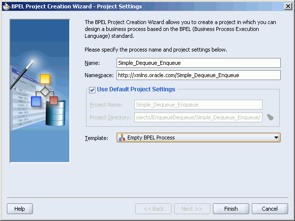
From Items, select BPEL Process Project and click OK. The BPEL Process Creation Wizard-Project Settings dialog box is displayed.
Perform the following as shown in Figure 6-26.
Enter Simple_Dequeue_Enqueue in the Name field.
Select Empty BPEL Process from the Templatelist.
Click Finish.
Figure 6-26 BPEL Process Creation Wizard-Project Settings Dialog Box
Create a Schema folder and copy the address-csv.xsd file to this folder.
Move the Schema folder to bpel sub directory of Simple_Dequeue_Enqueue project directory.
Drag a Partner Link activity from the Component Palette to the design area. The Create Partner Link dialog box is displayed.
Enter Inbound in the Name field and click the Define Adapter Service icon shown in Figure 6-27.
Click Next in the Welcome window of the Adapter Configuration Wizard. The Adapter Type window is displayed.
Select MQ Adapter and click Next. The Service Name window is displayed.
Enter inboundService in the Service Name field and click Next. The MQ Series Connection window is displayed.
Specify the JNDI name for the run-time connection, as shown in Figure 6-28 and click Next.
Select Get Message from MQ in the Operation Type window and click Next.
Enter test_in in the Queue Name field as shown in Figure 6-29 and click Next. The MQSeries adapter will dequeue the message from this queue.
Click Browse in the Messages window. The Type Chooser dialog box is displayed.
Select Project Schema Files, address-csv.xsd and then Root-Element, as shown in Figure 6-30 and click OK.
Click Next in the Messages window.
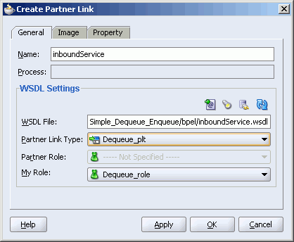
Click Finish. The Create Partner Link dialog box appears, as shown in Figure 6-31.
Figure 6-31 inboundService Create Partner Link dialog box
Click OK.
Perform the following steps to create an adapter service that will dequeue the message from a queue.
Drag a Partner Link activity from the Component Palette to the design area. The Create Partner Link dialog box is displayed.
Enter Outbound in the Name field and click the Define Adapter Service icon shown in Figure 6-27.
Click Next in the Welcome window of the Adapter Configuration Wizard. the Adapter Type window is displayed.
Select MQ Adapter and click Next. The Service Name window is displayed.
Enter outboundService in the Service Name field and click Next. The MQ Series Connection window is displayed.
Specify the JNDI name for the run-time connection as shown in Figure 6-28 and click Next. The Operation Type window is displayed.
Select Put Message into MQ and click Next.
Enter test_out in the Queue Name field. The MQSeries adapter will enqueue the message to this queue. Leave the other fields to default, as shown in Figure 6-32.
Click Next. The Messages window is displayed.
Click Browse. The Type Chooser dialog box is displayed.
Select Project Schema Files, address-csv.xsd and then Root-Element as shown in Figure 6-30 and click OK.
Click Next.
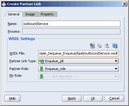
Click Finish. The Create Partner Link dialog box appears, as shown in Figure 6-33.
Figure 6-33 OutboundService Create Partner Link dialog box
Click OK.
Perform the following steps to create a Receive activity to instantiate a BPEL process instance when it receives a message from the MQSeries adapter:
Drag the Receive activity from the Components palette to the Drop Activity Here section.
Join the Receive activity to the inboundService partner link. The Edit Receive dialog box is displayed.
Enter ReadMsg in the Name field.
Click the Auto-Create Variable icon next to the Variable field. The Create variable dialog box is displayed, as shown in Figure 6-34.
Click OK. The ReadMsg_Dequeue_InputVariable variable is created.
Select Create Instance. The Edit Receive dialog box appears as shown in Figure 6-35.
Click OK.
Perform the following steps to create an Invoke activity that will send the message to partner link, which enqueues the message to the outbound queue:
Drag an Invoke activity below the receive activity from the Component palette .
Join the Invoke activity to the outboundService partner link. The Edit Invoke dialog box is displayed.
Enter WriteMsg in the Name field.
Click the Auto-Create Variable icon next to the Variable field. The Create variable dialog box is displayed.
Click OK. The WriteMsg_Enqueue_InputVariable variable is created.
Click OK.
Perform the following steps to create an Assign activity:
Drag an Assign activity from the Component Palette between the ReadMsg and the WriteMsg activity.
Double-click the Assign activity.
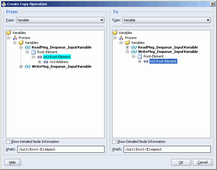
In the Copy operation tab, click Create and then select Copy Operation. The Create Copy Operation dialog box is displayed.
In the From group, select Variable, Process, Variables, ReadMsg_Dequeue_InputVariable, Root-Element, ns3:Root-Element, as shown in Figure 6-36.
In the To group, select Variable, Process, Variables, WriteMsg_Enqueue_InputVariable, Root-Element, ns3:Root-Element, as shown in Figure 6-36.
Figure 6-36 Create Copy Operation Dialog Box
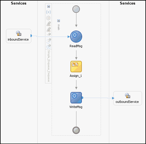
Click OK. The Assign activity dialog box appears, as shown in Figure 6-37.
Click OK. The Oracle JDeveloper appears, as shown in Figure 6-38.
Figure 6-38 Simple_Enqueue_Dequeue Use Case Design View
Perform the following steps to test the run-time of this scenario:
In the Applications window, click Applications and then right-click Simple_Dequeue_Enqueue.
Deploy the application.
Put the following text message to the test_in queue:
Name,Street1,Street2,City,State,Country;
The same text will be written to the test_out queue. Figure 6-39 displays the sample test_out queue to which the data has been written.
In this use case, the inbound MQSeries adapter dequeues the request message from MQSeries inbound queue test_in and publishes it to the BPEL process. The MQSeries adapter waits for the response from the BPEL process. When the MQSeries adapter receives the response, it enqueues the response message to the MQSeries queue specified in the replyTo queue of the request message. This use case consists of following sections:
This example assumes that you are familiar with basic BPEL constructs, such as activities and partner links, and Oracle JDeveloper environment for creating and deploying BPEL Process.
The MQSeries adapter must be configured as specified in Section 6.4, "Configuring the MQSeries Adapter" and two queue test_in and test_out should be created.
To define the schema of the messages, you require the address-csv.xsd and the address-fixedLength.xsd files. This files can be copied from the following location:
ORAHOME\bpel\samples\tutorials\121.FileAdapter\FlatStructure
Perform the following steps in Oracle JDeveloper to create an partner link that dequeues the request message from the inbound queue and enqueues the response message to the outbound queue:
In the Application Navigator, right-click Applications and select New Application. The Create Application dialog box is displayed.
Enter SyncReqRes in the Application Name field and click OK. The Create Project dialog box is displayed.
Click Cancel.
In the Applications Navigator, right-click SyncReqRes and select New Project. The New Gallery dialog box is displayed.
From Categories, select General and then Projects.
From Items, select BPEL Process Project and click OK. The BPEL Process Creation Wizard-Project Settings dialog box is displayed.
Perform the following:
Enter Sync_Req_Res in the Name field.
Select Empty BPEL Process from Template box.
Click Finish.
Create a Schema folder and copy the address-csv.xsd file to this folder.
Move the Schema folder to bpel sub directory of Sync_Req_Res project directory.
Drag a Partner Link activity from the Component Palette to the design area. The Create Partner Link dialog box is displayed.
Enter inbound_req_res in the Name field and click the Define Adapter Service icon shown in Figure 6-27. The Welcome window of the Adapter Configuration Wizard is displayed.
Click Next. The Adapter Type window is displayed.
Select MQ Adapter and click Next. The Service Name window is displayed.
Enter inboundService in the Service Name field and click Next. The MQ Series Connection window is displayed.
Specify the JNDI name for the run-time connection in the MQ Series Connection JNDI Name field as shown in Figure 6-28 and click Next. The Operation Type window is displayed.
Select Get message from MQ and Send Reply/Reports.
Select Synchronous option as shown in Figure 6-17 and click Next. The Get message from MQ and Send Reply/Reports window is displayed.
Enter test_in in the Queue Name field and click Next. The Response window shown in Figure 6-19 is displayed.
Specify the name of the response fallback queue in the Response Fallback Queue Name field and click Next. The Messages window shown in Figure 6-15 is displayed.
In the Get Messages Schema group, click Browse. The Type Chooser dialog box is displayed.
Select Project Schema Files, address-csv.xsd and then Root-Element and click OK.
In the Send Messages Schema group, click Browse. The Type Chooser dialog box is displayed.
Click Browse in the Messages window. The Type Chooser dialog box is displayed.
Select Project Schema Files, address-fixedLength.xsd and then Root-Element and click OK.
Click Next in the Messages window.
Click Finish.
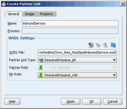
In the Create Partner Link dialog box, select Dequeue_role from the My Role box as shown in Figure 6-40.
Figure 6-40 Synchronous Request-Response Use Case Create Partner Link Dialog Box
Click OK.
Perform the following steps to create a Receive activity that instantiates a BPEL Process instance when it receives a message from the MQSeries adapter:
Drag the Receive activity from the Components palette to the Drop Activity Here section.
Join the receive activity to the inboundService partner link. The Edit Receive dialog box is displayed.
Enter ReadMsg in the Name field.
Click the Auto-Create Variable icon next to the Variable field. The Create variable dialog box is displayed.
Click OK. A ReadMsg_DequeueEnqueue_InputVariable variable is created.
Select Create Instance. The Edit Receive dialog box appears, as shown in Figure 6-35.
Click OK.
Perform the following steps to create a Reply activity that will send the response to the inboundService partnerlink.
Drag the Reply activity from the Components palette to below the ReadMsg activity.
Join the reply activity to the inboundService partner link. The Edit Reply dialog box is displayed.
Enter ReplyMsg in the Name field.
Click the Auto-Create Variable icon next to the Variable field. The Create variable dialog box is displayed.
Click OK. A ReplyMsg_DequeueEnqueue_OutputVariable variable is created. The Edit Reply dialog box appears, as shown in Figure 6-42.
Click OK.
Perform the following steps to map the ReadMsg_DequeueEnqueue_InputVariable variable to ReplyMsg_DequeueEnqueue_OutputVariable variable:
Drag the Transform activity from the Components palette to between the ReadMsg and the ReplyMsg activity.
Double-click the Trasnform activity.
From the Source Variable box, select ReadMsg_DequeueEnqueue_InputVariable.
From the Target Variable box, select ReplyMsg_DequeueEnqueue_OutputVariable.
Click the Create Mappings icon. The Transformation_1.xsl window opens.
Drag the tns:Address element from <source>panel to the Address element of the <target> panel. The Auto Map Preferences dialog box is displayed, as shown in Figure 6-43.
Figure 6-43 Auto Map Preferences Dialog Box
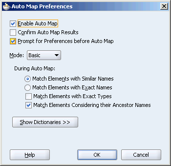
Deselect Match Elements Considering their Ancestor Names and click OK.
Drag a concat function from the Components palette to the Street1 node in the <source> panel.
Join the Street2 node to the Concat function. The Transformation_1.xsl window appears as shown in .
Close the Transformation_1.xsl window.
Perform the following steps to test the run-time of this scenario:
In the Applications navigator, click Applications and then right-click Sync_Req_Res.
Deploy the application.
Put the following text message to the test_in queue:
Name,Street1,Street2,City,State,Country;
The same text will be written to the test_out queue in the following format:
Name,Street1Street2,City,State,Country;
A series of demonstrations, activity and conceptual reference materials, and tutorials are provided to increase conceptual knowledge and hands-on experience with Oracle Enterprise Service Bus and Oracle BPEL Process Manager adapters.
These samples are available in the Samples folder.
In addition, you can find updated adapter tutorials at following location:
http://www.oracle.com/technology/products/integration/adapters/dev_support.html#tutorials