Concepts and Architecture
|
|
Overview
BEA AquaLogic Service Bus—part of BEA's new family of Service Infrastructure Products (AquaLogic)—combines intelligent message brokering with service monitoring and administration to provide a unified software product for implementing and deploying your Service-Oriented Architecture (SOA). This converged approach adds a scalable, dynamic routing and transformation layer to your enterprise infrastructure, plus service lifecycle management capabilities for service registration, service usage, and Service Level Agreement (SLA) enforcement.
AquaLogic Service Bus is a configuration-based, policy-driven Enterprise Service Bus (ESB). It provides a feature-rich console for dynamic service and policy configuration, as well as for system monitoring and operations tasks. The AquaLogic Service Bus Console enables you to respond rapidly and effectively to changes in your service-oriented environment.
AquaLogic Service Bus relies on WebLogic Server run-time facilities. It leverages WebLogic Server capabilities to deliver functionality that is highly available, scalable, and reliable.
This topic introduces AquaLogic Service Bus. It is intended for enterprise architects, operations specialists, and security architects who are responsible for messaging and SOA. It includes the following sections:
- Introducing AquaLogic Service Bus
- AquaLogic Service Bus Core Feature Set
- AquaLogic Service Bus Message Brokering
- AquaLogic Service Bus Architecture
Introducing AquaLogic Service Bus
Enterprise architects responsible for messaging and SOA initiatives face a number of challenges in today's enterprise:
- Introducing dynamic behavior and run-time configuration capabilities into a system
- Reusing services that are developed across the enterprise and managing their lifecycle
- Ensuring consistent use of the enterprise services
- Ensuring enterprise services are secure
- Ensuring that the enterprise services comply with the IT policies
- Monitoring and auditing service usage and managing system outages
In short, the goal of the enterprise architect and other specialists is to reuse, streamline, and maintain control over their IT infrastructure. AquaLogic Service Bus is designed to help you achieve these goals.
AquaLogic Service Bus is a true ESB product specifically targeted for service-oriented integration, managing Web Services, and providing traditional message brokering across heterogeneous IT environments. AquaLogic Service Bus's lightweight, stateless, high-performance architecture delivers an intermediary for use as a core element of distributed services networks.
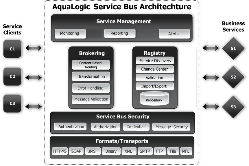
AquaLogic Service Bus is policy-driven. It enables you to establish loose coupling between service clients and business services while maintaining a centralized point of security control and monitoring as shown in the following figure.
Figure 1-1 AquaLogic Service Bus High-Level Architecture
With AquaLogic Service Bus you implement service integration relationships dynamically through configuration of policies and proxy services. This approach enables your service architectures to evolve rapidly with respect to the following system characteristics:
- Security
- Service location
- Availability and responsiveness
- Data formats
- Logging and monitoring
- Transport protocols and communications paradigms
Because of the intermediary nature of the proxy service, you can use AquaLogic Service Bus to resolve differences between service client and business service requirements in the following areas:
- Payload contents and schema
- Envelope protocols
- Transport protocols
- Point-to-point and publish and subscription protocols
- One way and request/response paradigms
- Synchronous and asynchronous communication
- Security compliance
AquaLogic Service Bus persists policy, proxy service, and related resource configurations in metadata that you can propagate from development through staging to production environments, and then modify as required. The AquaLogic Service Bus message brokering engine accesses this configuration information from its metadata repository.
A key design philosophy of AquaLogic Service Bus is the physical separation of management functions from service implementations. This separation allows implementations to evolve independently and dynamically as driven by the needs of the business without requiring costly infrastructure development efforts. As part of an enterprise's messaging fabric, AquaLogic Service Bus can be used horizontally across many applications and systems, spanning service implementations in different departments built by different teams.
AquaLogic Service Bus Core Feature Set
By fusing the concepts of ESB, message brokering, and Web Services Management (WSM) into a single product, AquaLogic Service Bus provides the foundation for management and integration of messages and services.
The following table describes the core features of AquaLogic Service Bus.
Table 1-1 AquaLogic Service Bus Core Features
AquaLogic Service Bus Architecture
AquaLogic Service Bus is an intermediary that takes in messages, processes them to determine where to route them, and transforms them as specified. It receives messages through a transport protocol such as JMS and sends out messages again through the same or another specified transport protocol. Message response follows the inverse path. The message processing by AquaLogic Service Bus is driven by metadata specified as the message flow definition for a proxy service in the AquaLogic Service Bus Console.
Deployment Topology
AquaLogic Service Bus runs on WebLogic Server 9.0 and can be deployed in the following configurations:
- On a single server that also serves as the administration server.
- On a cluster of servers. A cluster consists of a clustered set of managed servers that perform the message processing. A domain has only one cluster and that cluster has AquaLogic Service Bus deployed to it. This cluster can host other applications in addition to AquaLogic Service Bus. There is one administration server in a clustered domain.
AquaLogic Service Bus can manage and control many distributed service endpoints, thereby providing centralization in the enterprise. For example, you can deploy AquaLogic Service Bus as a single hub that manages all the Web service traffic in an enterprise.
You can horizontally scale an AquaLogic Service Bus hub by clustering the underlying WebLogic Server. This allows the messaging load to be homogeneously spread over the servers in the cluster, thereby preventing bottlenecks in the system. In addition, heterogeneous AquaLogic Service Bus hubs can be connected to create a distributed AquaLogic Service Bus network.
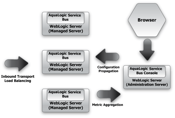
AquaLogic Service Bus supports clustering of the WebLogic managed servers. It propagates configuration and metadata automatically to the managed servers for fast local retrieval, and it automatically collects monitoring metrics from all the managed servers for aggregation and display on the AquaLogic Service Bus Console.
The following figure shows the flow of message data in a basic AquaLogic Service Bus cluster topology.
Figure 1-2 Clustering and High Availability
Development, Staging, and Production Domains
AquaLogic Service Bus supports best practices for change management in your enterprise systems by enabling you to configure resources and services in a controlled environment. You can then export the configurations for import into separate staging domains for testing and final preparation for promotion into a production domain. AquaLogic Service Bus provides you with the ability to reconfigure environment-specific elements as necessary to meet the requirements of the importing domain.
AquaLogic Service Bus Message Brokering
AquaLogic Service Bus provides intelligent message brokering functionality for your SOA. The following sections describe the key concepts associated with AquaLogic Service Bus message structures and message processing.
Business Services and Proxy Services
AquaLogic Service Bus provides intelligent message brokering between business services (such as enterprise services and databases) and service clients (such as presentation applications or other business services) through proxy services that you configure using the AquaLogic Service Bus Console.
Business Services
Business services are AquaLogic Service Bus definitions of the enterprise services with which you want to exchange messages. Using the AquaLogic Service Bus Console, you configure a business service by defining its interface in terms of WSDLs and the type of transport it uses, its security requirements, and other characteristics.
For information on how to configure a business service using the AquaLogic Service Bus Console, see "Adding a Business Service" in Business Services in the AquaLogic Service Bus Console Online Help.
Proxy Services
Proxy services are AquaLogic Service Bus definitions of intermediary Web services that are hosted locally on AquaLogic Service Bus. Using the AquaLogic Service Bus Console, you configure a proxy service by defining its interface in terms of WSDLs and the type of transport it uses, the logic of message processing in message flow definitions, and by configuring policies.
With AquaLogic Service Bus message brokering, service clients exchange messages with an intermediary proxy service instead of directly with a business service. A proxy service can have an interface that is identical (same WSDL and transport) to a business service with which the proxy service communicates, or the proxy service can have an interface that differs from that of the business service in terms of WSDL, transport type, or both.
Since a proxy service can route messages to multiple business services, you can choose to configure a proxy service with an interface that is independent of the business services with which the proxy service communicates. In such cases, you would configure a message flow definition to route a message to the appropriate business service and map the message data into the format required by the business service's interface.
For more information about the structure of proxy services, see Message Flow Definition.
Message Processing
A message is a formula used by WebLogic Server to share information among applications. Messages can contain data or status information about application processes, or instructions for the recipient, or both. AquaLogic Service Bus enables you to route messages based on their contents and to perform transformations on that content.
The processing of messages occurs in the following sequence of events:
After a message is sent to an endpoint (either a business service or another proxy service),AquaLogic Service Bus processes the response message in a similar model as that described in the preceding sequence of events.
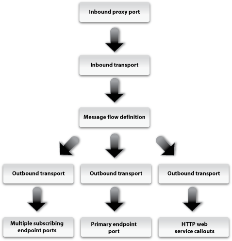
The following figure shows a high-level view of how messages flow through AquaLogic Service Bus, from inbound endpoint (a proxy service) to outbound endpoint (the transport URL for a service—typically a business service).
Figure 1-3 AquaLogic Service Bus Message Processing
The following sections describe each layer involved in this message processing.
Transport Layer (Inbound)
The first step for the message is the inbound transport layer, which is responsible for handling communication with the service client endpoint and acts as the entry point for messages into AquaLogic Service Bus. It supports a variety of communication protocols, such as HTTP and JMS. With regard to the message data itself, the inbound transport layer primarily deals with raw bytes in the form of input/output streams.
The inbound transport layer is simply for getting messages into the AquaLogic Service Bus system and sending the response back. It does not perform any data processing.
Message Flow Definition
Pipelines, branches, and route nodes define the implementation of AquaLogic Service Bus proxy services. Using the AquaLogic Service Bus Console, you configure the logic for the manipulation of messages in proxy service message flow definitions. This logic includes such activities as transformation, publishing, and reporting which are implemented as individual actions within the stages of a pipeline.
Pipeline Pairs
Pipeline logic occurs in pairs of definitions consisting of a request pipeline definition and a response pipeline definition. The request pipeline definition specifies the actions that AquaLogic Service Bus performs on request messages to the proxy service before invoking a business service or another proxy service. The response pipeline definition specifies the processing that AquaLogic Service Bus performs on responses from the service invoked by the proxy service before the proxy service returns a response. Routing is performed by a route node at the end of the message flow.
Note: WS-Security processing and authorization are transparently performed before pipeline execution.
Pipeline Execution Stages and Actions
Each pipeline is a sequence of stages. A stage is a user-configured processing step such as transformation or publishing. Messages fed into the pipelines are accompanied by a set of message context variables that contain the message contents and can be accessed or modified by actions in the pipeline stages.
The following table describes all of the actions possible in a AquaLogic Service Bus pipeline stage.
Operational Pipelines
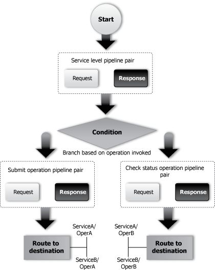
Each pipeline consists of a sequence of stages containing actions. However a single service level request pipeline might optionally branch out into operational pipelines (at most one per operation and optionally a default operational pipeline). The determination of the operation is done through user-selected criteria. The response processing starts with the relevant operation pipeline which then joins into a single service-level response pipeline.
The following figure shows an example of operation pipelines in a proxy service:
Figure 1-4 Example Message Flow
In the case of one-way operations, the response pipeline is executed with an empty message. This permits a response to be constructed for the proxy service, thus enabling bridging between request/response and one-way operations. The bridging mechanism means that proxy service input can be one-way while its output is request/response or vice versa. The proxy service either absorbs the response from the invoked service or generates one for the client.
Transport Layer (Outbound)
The outbound transport layer is responsible for handling communication with the destination endpoint. It supports a variety of communication protocols, such as HTTP and JMS. With regard to the message data itself, the transport layer primarily deals with raw bytes in the form of input/output streams.
The outbound transport layer is simply for getting messages out of the AquaLogic Service Bus system. It does not perform any data processing.


