Interoperability Solutions Guide
|
|
Interoperability with BEA Tuxedo
Introduction
BEA AquaLogic Service Bus and BEA Tuxedo can interoperate to use the services that each product offers.
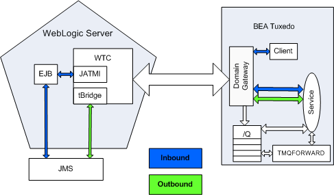
- When AquaLogic Service Bus uses services offered by BEA Tuxedo, a request for a Tuxedo service can be placed on a JMS queue and the reply to that request can be received from another JMS queue. The term "outbound" refers to this scenario.
- When BEA Tuxedo uses services offered by AquaLogic Service Bus, BEA Tuxedo services can call an EJB as though it were another BEA Tuxedo application. The term "inbound" refers to this scenario.
You can use the following related documentation to learn more about this environment:
- For information on setting up your AquaLogic Service Bus environment, see the AquaLogic Service Bus Administration Console Online Help.
- For information on setting up your BEA Tuxedo environment, see Setting Up a Tuxedo Application in the BEA Tuxedo documentation.
- For information about the WebLogic Tuxedo Connector, see WebLogic Tuxedo Connector in the WebLogic Server documentation.
- If you want to set up and use a working example of this interoperability scenario, see "Interoperability with AquaLogic Service Bus and Tuxedo" on the dev2dev web site.
The following diagram summarizes this message handling process:
This chapter includes the following sections:
- Using BEA Tuxedo Services from AquaLogic Service Bus (Outbound Example)
- Using AquaLogic Service Bus Services from BEA Tuxedo (Inbound Example)
Using BEA Tuxedo Services from AquaLogic Service Bus (Outbound Example)
The following sections describe how to use BEA Tuxedo services from AquaLogic Service Bus:
- Implementation Overview
- Before You Begin
- Configuring WebLogic Tuxedo Connector and the Tuxedo Queuing Bridge
- Configuring a New Business Service
- Testing Your Configuration
Implementation Overview
AquaLogic Service Bus can utilize services offered by BEA Tuxedo using WebLogic Tuxedo Connector. WebLogic Tuxedo Connector provides a JMS bridge (tBridge) that can directly call Tuxedo services.
After you configure WebLogic Tuxedo Connector and the Tuxedo Queuing Bridge, a request for a Tuxedo service can be placed on a JMS queue and the reply to that request can be received from another JMS queue. tBridge handles the conversion from the JMS message to a Tuxedo buffer type, calls the imported Tuxedo service, converts the reply buffer back to a JMS message type, and places the converted reply onto a JMS queue. The request to Tuxedo can either be made directly to a service or placed on a Tuxedo /Q queue.
Before You Begin
Gather the following information about the Tuxedo application that AquaLogic Service Bus will use:
- ID of the Tuxedo local access point.
- Network address of the Tuxedo local access point.
- Name of the exported Tuxedo service.
- Whether the service needs XML-to-FML and FML-to-XML conversion.
If XML-to-FML and FML-to-XML conversion is needed, you will need to add one or more Field Table classes to a resource section in the WebLogic Tuxedo Connector configuration. This task is described in Create Field Table Classes (if Required).
The example described in the following sections assumes the use of FML/FML32 buffer types.
- ID of the access point that the Tuxedo domain gateway will use to refer to this WebLogic Tuxedo Connector instance.
- Network address that the Tuxedo domain gateway has defined for this WebLogic Tuxedo Connector Local Access Point.
Prior to configuring the Tuxedo Queuing Bridge, you must create several JMS queues if they do not already exist. Queues are required for the following purposes:
- One or more queues on which to place requests to the Tuxedo service
- A queue to pick up replies from the Tuxedo service
- A queue to receive messages that failed to be delivered to Tuxedo
- A queue to receive error replies from the called service
Configuring WebLogic Tuxedo Connector and the Tuxedo Queuing Bridge
You configure WebLogic Tuxedo Connector and the Tuxedo Queuing Bridge (tBridge) using the WebLogic Server Administration Console. For additional information about the WebLogic Tuxedo Connector, see WebLogic Tuxedo Connector in the WebLogic Server documentation.
Log in to the WebLogic Server Administration Console. Perform the configuration steps in the order presented, using the instructions in the following sections.
- Create a New WTC Server
- Create a Local Access Point
- Create a Remote Access Point
- Create a WTC Imported Service
- Create Field Table Classes (if Required)
- Create a Queuing Bridge
- Create a Redirection
- Activate Changes
Create a New WTC Server
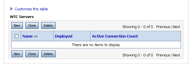
- Click Lock & Edit; this allows you to make changes. A display similar to Figure 2-1 appears:
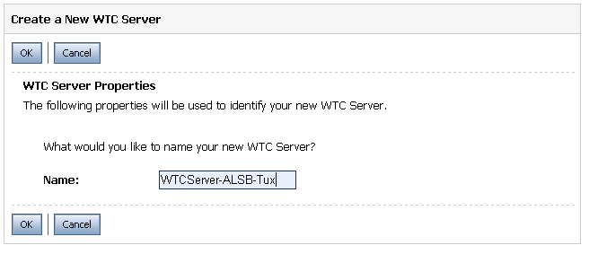
- Click New to add the new WTC server. A display similar to Figure 2-2 appears:
Figure 2-2 New WTC Server Data Entry Display
Create a Local Access Point
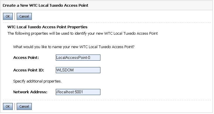
- Click New to create a new WTC Local Access Point. A display similar to Figure 2-3 appears:
Access Point - A name for this access point.
Access Point ID - The name WebLogic Server will use to refer to the access point. This value must match the Remote Access Point ID that the Tuxedo domain gateway has been configured to use for this WTC instance.
Network Address - This value must match the remote network address that the Tuxedo domain gateway has been configured to use for this WTC instance.
Figure 2-3 New Local Access Point Data Entry Display
Create a Remote Access Point
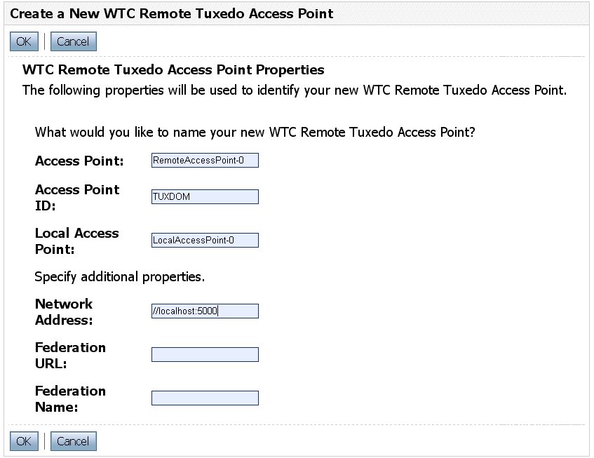
- Click New to create a new WTC Remote Access Point. A display similar to Figure 2-4 appears:
Access Point - A name for this access point.
Access Point ID - The name WebLogic Server will use to refer to the access point. This value must match the Local Access Point ID that the Tuxedo domain gateway has been configured to use for this WTC instance.
Local Access Point - The name of WTC Local Access Point.
Network Address - This value must match the local network address that the Tuxedo domain gateway has been configured to use for this WTC instance.
Figure 2-4 New Remote Access Point Data Entry Display
Create a WTC Imported Service
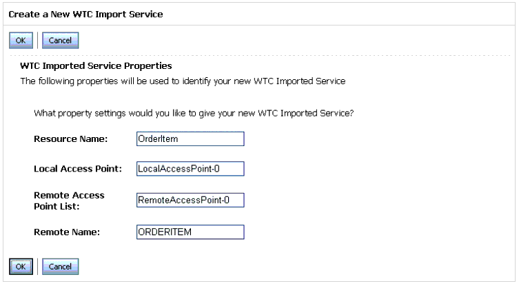
- Click New to create a new WTC Imported Service. A display similar to Figure 2-5 appears:
Resource Name - The name WebLogic Server will use to refer to the service (including the tBridge)
Local Access Point - The name of the just created local access point
Remote Access Point List - The name of the newly created remote access point
Remote Name - The name of the service as exported by the remote Tuxedo system
Figure 2-5 New WTC Import Service Data Entry Display
Create Field Table Classes (if Required)
If the Tuxedo service expects FML or FML32 buffers, you must add one or more Field Table classes to a resource section in the WebLogic Tuxedo Connector configuration. To create the classes, use the weblogic.wtc.jatmi.mkfldclass utilities for FML field tables or the weblogic.wtc.jatmi.mkfldclass32 utility for FML32 field tables.
If you do not need to create Field Table classes, skip to Create a Queuing Bridge.
To create Field Table classes, follow these steps:
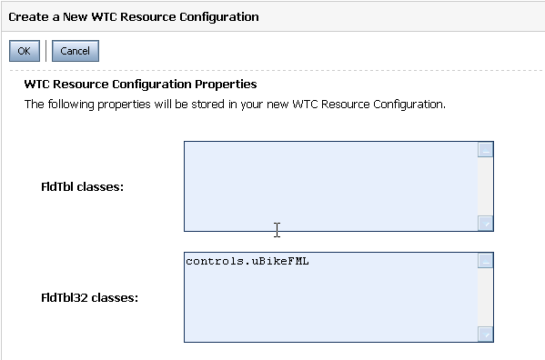
- Click New to create a new WTC Resource Configuration. A display similar to Figure 2-6 appears:
- Add the full class names to the FldTbl classes or FldTbl32 classes fields. The classes must be on the WebLogic Server classpath; you might need to change the WebLogic Server classpath. For information on setting the WebLogic Server classpath, see Modifying the Classpath in the WebLogic Server Command Reference.
Figure 2-6 New Field Table Class Data Entry Display
Create a Queuing Bridge
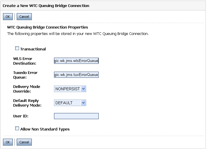
- Click New to create a new Queuing Bridge. A display similar to Figure 2-7 appears:
Figure 2-7 New WTC Queuing Bridge Data Entry Display
Create a Redirection
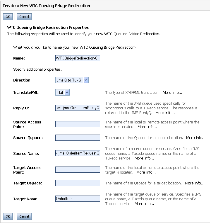
- Click New to create a redirection for the service that is to be called in Tuxedo. A display similar to Figure 2-8 appears:
Direction -Specify JmsQ to TuxS.
TranslateFML - If the Tuxedo service requires XML-to-FML and FML-to-XML translation, select Flat.
Reply Q - Enter the JNDI name of the JMS queue that is to receive the replies from the Tuxedo service.
Source Name - Enter the JNDI name of the JMS queue that is to receive the requests for the Tuxedo service.
Target Access Point - Enter the name of the remote access point that you created previously.
Target Name - Enter the name of the imported Tuxedo service that you created previously.
Figure 2-8 New WTC Redirection Data Entry Display
Activate Changes
To activate the changes you made, click Activate Changes on the WebLogic Server Administration Console.
Configuring a New Business Service
To utilize the Tuxedo service from AquaLogic Service Bus, you must configure a new Business Service in the AquaLogic Service Bus Console. For more information about Business Services, see Business Services in the AquaLogic Service Bus Console Online Help.
Log in to the AquaLogic Service Bus Console. Perform the configuration steps in the order presented, using the instructions in the following sections.
Add a New Project
Add a Business Service
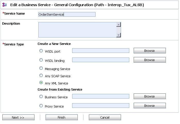
The Edit a Business Service - General Configuration page displays, as shown in Figure 2-9.
Figure 2-9 New Business Service Page 1
Service Name - The name of the service
Service Type - Select Any XML Service (the default)
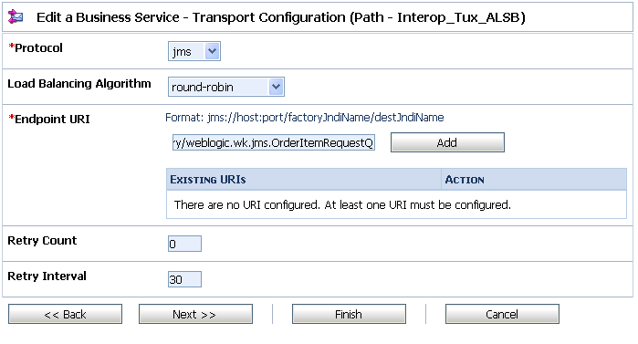
Click Next to display the Edit a Business Service - Transport Configuration page as shown in Figure 2-10.
Figure 2-10 New Business Service Page 2
Add a Proxy Service
Create a proxy service for testing purposes. For more information about proxy services, see Proxy Services in the AquaLogic Service Bus Console Online Help.
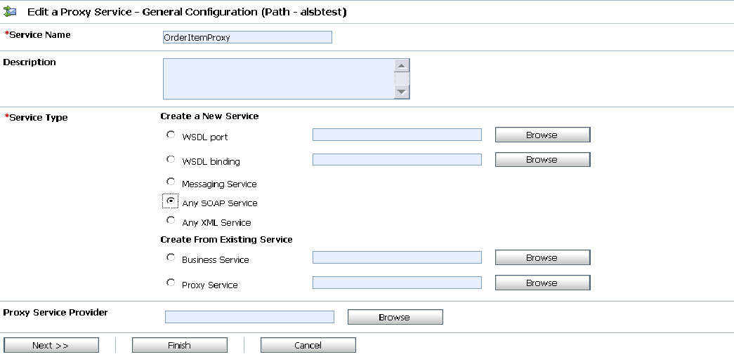
The Edit a Proxy Service - General Configuration page displays, as shown in Figure 2-11.
Figure 2-11 New Proxy Service Data Entry Page 1
Service Name - The name of the service
Service Type - Select Any SOAP Service
Click Next to display the Edit a Proxy Service - Transport Configuration page, as shown in Figure 2-12.
Figure 2-12 New Proxy Service Data Entry Page 2
Configure the Proxy Service
AquaLogic Service Bus Message Flows define the implementation of proxy services. Message flows can include zero or more pipeline pairs: request and response pipelines for the proxy service (or for the operations on the service) and error handler pipelines that can be defined for stages, pipelines, and proxy services. Pipelines can include one or more stages, which in turn include actions. To change the routing behavior of the proxy service you will edit this message flow to:
- Add a route node
- Configure an action to route the Proxy Service to the Business Service resource that you created previously
- In the AquaLogic Service Bus Console navigation panel, select Resource Browser from the list of available choices, if it is not already selected.
The Resource Browser pane is opened in the navigation panel and the Summary of Proxy Services project page is displayed in the console.
- In Options, click the Message Flow icon
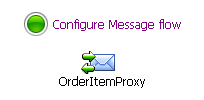
 . A display similar to Figure 2-13 appears:
 The Edit Message Flow page for the proxy service you created previously is displayed. This page displays the default message flow configuration. The default configuration consists of a start node. This is the minimum configuration of a message flow. The behavior of the message flow is sequential.
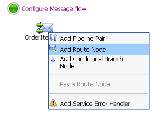
- Click the Start Node. From the popup menu select the Add Route Node link, as shown in Figure 2-14.
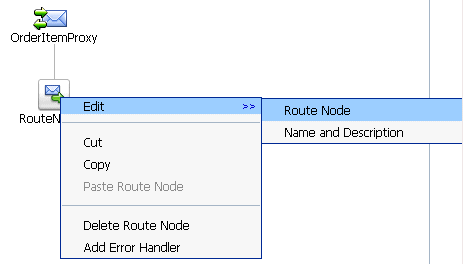
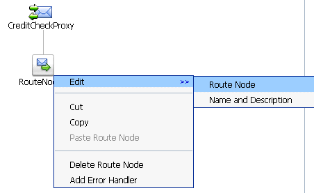
- Click the route node and from the pop up menu select Edit > Route Node, as shown in Figure 2-15:
The Edit Stage Configuration page is displayed. The page contains a single link, Add an Action.
A stage is an element of a pipeline and it is a container for actions defined in a pipeline. Actions are the elements of a pipeline stage that define the handling of messages as they flow through a proxy service.
- Click the Add an Action link, then select Routing from the popup menu, as shown in Figure 2-16:
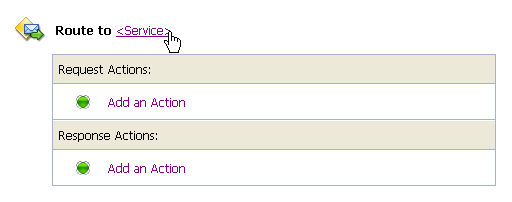
The Edit Stage Configuration page changes to display the contents of the action. The contents of the action are defined by the type of node we created—a route node.
- In Route to <Service>, click <Service>, as shown in Figure 2-17:
- Select the Business Service that you created in Add a Business Service.
Figure 2-13 Message Flow Default Display
Figure 2-14 Convert to Route Node Display
Figure 2-15 Edit Route Node Display
Figure 2-16 Message Flow Routing Display
Figure 2-17 Route to Service Display
The configuration is completed and ready to test.
Testing Your Configuration
Now that you have configured AquaLogic Service Bus to work with BEA Tuxedo, you can test the application. One way to test the configuration is to use a WebLogic Workshop-based application, by setting up a web service proxy and calling it using a default pipeline.
The following list of tasks summarizes the process of testing outbound usage of BEA Tuxedo by AquaLogic Service Bus.
Using AquaLogic Service Bus Services from BEA Tuxedo (Inbound Example)
The following sections describe how to use AquaLogic Service Bus services from BEA Tuxedo:
- Implementation Overview
- Before You Begin
- Adding Field Classes to EJB's JAR File
- Testing Your Configuration
Implementation Overview
The WebLogic Tuxedo Connector allows BEA Tuxedo applications to call an EJB as though it were another BEA Tuxedo application. This scenario uses a particular example EJB that performs the function of receiving a Tuxedo service request, translating the buffer as necessary, and placing the resulting message on a JMS queue. The method described in this document is based on setting up an EJB using deployment descriptors; this method also provides translation of Tuxedo buffers to and from JMS messages.
Before You Begin
Gather the following information about the AquaLogic Service Bus application that BEA Tuxedo will use:
- ID of the Tuxedo local access point and add this ID as a WLS user.
- Network address of the Tuxedo local access point.
- Name of the exported Tuxedo service.
- Whether the service needs XML-to-FML and FML-to-XML conversion.
If XML-to-FML and FML-to-XML conversion is needed, you will need to add one or more Field Table classes; these classes are bundled in the jar with the EJB and loaded dynamically from the EJB's jar.
- ID of the access point that the Tuxedo domain gateway will use to refer to this WebLogic Tuxedo Connector instance.
- Network address that the Tuxedo domain gateway has defined for this WebLogic Tuxedo Connector Local Access Point.
You must create the following JMS queues if they do not already exist:
- One or more queues on which to place requests to the AquaLogic Service Bus service
- A queue to pick up replies from the AquaLogic Service Bus service
Configuring the Sample EJB ToQSBean
Set environment entries in the ejb-jar.xml file and set the name of the exported service that WebLogic Tuxedo Connector will allow other domains to call. The following sections contain instructions for these tasks.
Edit the ejb-jar.xml File
In the ejb-jar.xml file, set the following environment entries:
- JMSConnectionFactory - Set this to the JNDI name of the JMS connection factory that the EJB should use.
- ToQueueName - Set this to the JNDI name of the JMS queue into which the EJB should place incoming requests. This string can contain the indicator "
%s," which causes the actual service name to be substituted. For example, if the EJB is deployed to provide the CREDITCHECK ATMI service, setting this string toweblogic.jms.%sServiceRequestQresults in a JNDI name ofweblogic.jms.CREDITCHECKServiceRequestQ. - ReplyQueueName - Set this to the JNDI name of the JMS queue into which AquaLogic Service Bus places replies. This string can contain a "
%s" to make this setting more generic. - FieldTables - A comma-separated list of the FML/FML32 field table classes required for any FML/XML translation.
Edit the weblogic-ejb-jar.xml File
In the weblogic-ejb-jar.xml file, set the EJB's JNDI name to tuxedo.services.svcnameHome where svcname is the ATMI service name that the deployment supports. This is the name of the exported service that WTC allows other domains to call.
For reference information on the structure of the weblogic-ejb-jar.xml file, see weblogic-ejb-jar.xml Deployment Descriptor Reference in Programming WebLogic Enterprise JavaBeans.
Adding Field Classes to EJB's JAR File
This task is optional if you set up field classes as described in Create Field Table Classes (if Required). Any Field Table class files required for XML to FML and FML to XML conversion must be included in the EJB's JAR file. For instructions on performing this task, see the WebLogic Server Javadoc.
Building and Deploying the EJB
Deploying an EJB enables WebLogic Server to serve the components of an EJB to clients. You can deploy an EJB using one of several procedures, depending on your environment and whether or not your EJB is in production.
For general instructions on deploying WebLogic Server applications and modules, including EJBs, see Deploying Applications to WebLogic Server in the WebLogic Server documentation. For EJB-specific deployment issues and procedures, see Deployment Guidelines for Enterprise Java Beans in Programming WebLogic Enterprise JavaBeans.
Configuring WebLogic Tuxedo Connector
You configure WebLogic Tuxedo Connector using the WebLogic Server Administration Console. For additional information about the WebLogic Tuxedo Connector, see WebLogic Tuxedo Connector in the WebLogic Server documentation.
Log in to the WebLogic Server Administration Console and perform these steps in the order presented.
Note: If you performed the WTC setup described in Configuring WebLogic Tuxedo Connector and the Tuxedo Queuing Bridge, you can skip the corresponding tasks described here; the only required task is to create a WTC Export Service.
To complete this configuration, you will perform the tasks described in the following sections:
- Create a New WTC Server
- Create a Local Access Point
- Create a Remote Access Point
- Create a WTC Export Service
Create a New WTC Server
- Click Lock & Edit; this allows you to make changes. A display similar to Figure 2-18 appears:
- Click New to add the new WTC server. A display similar to Figure 2-19 appears:
Figure 2-18 WTC Server Display
Figure 2-19 New WTC Server Data Entry Display
Create a Local Access Point
- Click New to create a new WTC Local Access Point. A display similar to Figure 2-20 appears:
Access Point - A name for this access point.
Access Point ID - The name WebLogic Server will use to refer to the access point. This value must match the Remote Access Point ID that the Tuxedo domain gateway has been configured to use for this WTC instance.
Network Address - This value must match the remote network address that the Tuxedo domain gateway has been configured to use for this WTC instance.
Figure 2-20 New Local Access Point Data Entry Display
Create a Remote Access Point
- Click New to create a new WTC Remote Access Point. A display similar to Figure 2-21 appears:
Access Point - A name for this access point.
Access Point ID - The name WebLogic Server will use to refer to the access point. This value must match the Local Access Point ID that the Tuxedo domain gateway has been configured to use for this WTC instance.
Local Access Point - The name of WTC Local Access Point.
Network Address - This value must match the local network address that the Tuxedo domain gateway has been configured to use for this WTC instance.
Figure 2-21 New Remote Access Point Data Entry Display
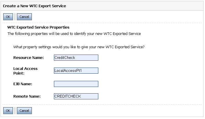
Create a WTC Export Service
- Click New to create a new WTC Exported Service. A display similar to Figure 2-22 appears:
Resource Name - The name WebLogic Server will use to refer to the service (including the tBridge)
Local Access Point - The name of the local access point you created earlier
EJB Name - The complete name of the EJB home interface to use when invoking a service
Remote Name - The name of the service as exported by the remote Tuxedo system
Figure 2-22 New WTC Export Service Data Entry Display
Adding and Configuring a Proxy Service
To utilize theAquaLogic Service Bus service from Tuxedo, you must configure a new proxy service using the AquaLogic Service Bus Console. For more information about proxy services, see Proxy Services in the AquaLogic Service Bus Console Online Help.
Log in to the AquaLogic Service Bus Console and perform these steps in the order presented.
To complete this configuration, you will perform the tasks described in the following sections:
Add a New Project
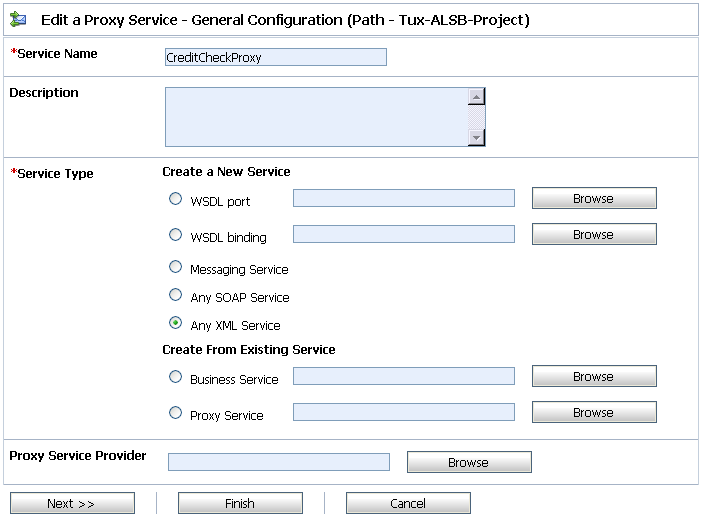
Add a Proxy Service
The Edit a Proxy Service - General Configuration page displays, as shown in Figure 2-23.
Figure 2-23 New Proxy Service Data Entry Page 1 - Inbound
Service Name - The name of the service
Service Type - Select Any XML Service (the default)
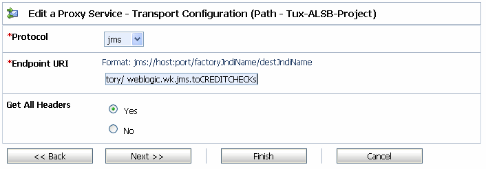
Click Next to display the Edit a Proxy Service - Transport Configuration page, as shown in Figure 2-24.
Figure 2-24 New Proxy Service Data Entry Page 2 - Inbound
Configure the Proxy Service
AquaLogic Service Bus Message Flows define the implementation of proxy services. Message flows can include zero or more pipeline pairs: request and response pipelines for the proxy service (or for the operations on the service); and error handler pipelines that can be defined for stages, pipelines, and proxy services. Pipelines can include one or more stages, which in turn include actions. To change the routing behavior of the proxy service you will edit this message flow to:
- Add a route node
- Configure an action to route the Proxy Service to the Business Service resource that you created previously
- In the AquaLogic Service Bus Console navigation panel, select Resource Browser from the list of available choices, if it is not already selected.
The Resource Browser pane is opened in the navigation panel and the Summary of Proxy Services project page is displayed in the console.
- In Options, click the Message Flow icon
 . A display similar to Figure 2-25 appears:
 The Edit Message Flow page for the proxy service you created previously is displayed. This page displays the default message flow configuration. The default configuration consists of a start node. This is the minimum configuration of a message flow. The behavior of the message flow is sequential.
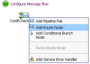
- Click the Start Node. From the popup menu select the Add Route Node link, as shown in Figure 2-26.
- Click the route node and from the pop up menu select Edit > Route Node, as shown in Figure 2-27:
The Edit Stage Configuration page is displayed. The page contains a single link, Add an Action.
A stage is an element of a pipeline and it is a container for actions defined in a pipeline. Actions are the elements of a pipeline stage that define the handling of messages as they flow through a proxy service.
- Click the Add an Action link, then select Routing from the popup menu, as shown in Figure 2-28:
The Edit Stage Configuration page changes to display the contents of the action. The contents of the action are defined by the type of node we created—a route node.
- In Route to <Service>, click <Service>, as shown in Figure 2-29:
Figure 2-25 Message Flow Default Display
Figure 2-26 Convert to Route Node Display
Figure 2-27 Edit Route Node Display
Figure 2-28 Message Flow Routing Display
Figure 2-29 Route to Service Display
The configuration is completed and ready to test.
Testing Your Configuration
Now that you have configured BEA Tuxedo to work with AquaLogic Service Bus, you can perform a test to verify that it is working correctly. If you are using XML-to-FML32 and FML32-to-XML conversions, you can test this configuration using the "ud32" Tuxedo client program that is included with BEA Tuxedo. (If you are using FML conversions, you can use the "ud" client.) ud32 reads input consisting of text representation of FML buffers. For more information, see the information on the ud and ud32 commands in the Tuxedo Command Reference.
If you are not using XML-to-FML and FML-to-XML conversions, you must develop a test client program in Tuxedo to test this configuration. To find information on this task, refer to the BEA Tuxedo documentation.
