Using the Product Workbench
This chapter covers the following topics:
- Product Workbench Overview
- Item Management
- Creating Items
- Overview of Product Structure and Bills of Material Management
- Managing Bills of Material/Product Structures
- Importing Product Structure/BOM
- Using Multilevel Structures
- Managing Structures Using Effectivity Control
- Excluding Structures
- Exclusion Rules by Product Revisions
- Excluding Transaction Attribute Value Set Values
- Overriding Component Attribute Values
- Creating Structures
- Viewing Structure Information
- Editing Structure Information
- Using Defined Structure Names and Types
- Viewing Structures in the Context of a Change Order
- Marking Up Structures
- Creating New Issues or Change Orders
- Valid Component Types
Product Workbench Overview
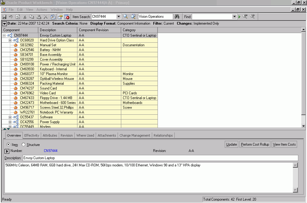
You can use the Product Workbench to edit, view, and manage product information, including product structures/bills of material and structured attributes using the feature-rich graphical user interface. You can use the drag & drop, and red-lining/markup inside a familiar interface. This tool is for users who frequently need to work with complex product structures and need quick response time and extra flexibility that a windows based UI can provide.
Product Workbench's Advanced Graphical User Interface
Oracle Product Workbench’s graphical interface improves productivity and enables easy access to critical information. The windowing, mouse actions, icons, and built-in drilldowns enable easy transactions and inquiries. The workbench provides all the relevant information in different windows that can be displayed simultaneously. You can resize, minimize, maximize and close these windows based on your requirement. The interface is also available in multiple languages with natural language support (NLS). NLS enables users to decide how they want, for example, to format their date field values
Product Workbench Advanced Graphical User Interface
Item Management
Favorites List
Oracle Product Workbench allows users to view and edit the list of favorite items for different organizations. The Favorites list comprises a list of the frequently accessed items per user per organization. It is intended to reduce the effort in locating an item every time the user wants to refer/edit information related to it. Through this list, the user can access the information quickly without searching for items.
Important: You can only assign an item to only those organizations to which you have permission.
Editing Favorites List
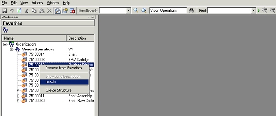
Users can select an item from the item search results or from the structure window and add the selected item to this list by a right click menu action.
Similarly, users can select an entry from the Favorites list and remove the selected item from the list by another right click menu action.
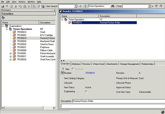
Viewing Items from Favorite List
Users can select an entry from the Favorites list and invoke the details window by a right click action. A new window is opened displaying the item information organized over different TABs. If the user changes the selection in the favorites list, the item information being displayed in the details window also changes appropriately.
Favorites page
Item Details
Selecting Multiple Organizations
You can select and work in multiple organizations in the Product workbench. In the left pane of the Product Workbench, you can use the right click mouse function to Search and Select Organization. This will allow you to select another organization other than the default organization already displayed.
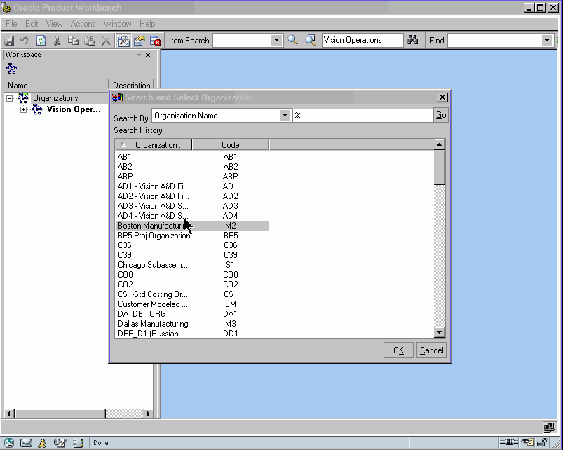
The organization and its items you have now selected will display in the Product Workbench.
You can select and open these items in the structure windows.
Note: When you set the organization active in the left pane , all further action like Item Search that you select from the Edit menu are by default performed on your active organization. If you have a Structure already open in organization M1 and now set the active organization to V1, action(s) that you perform in that Structure Window would continue to be performed only in M1 and would not switch to V1.
(In the Product Workbench you can conduct multiple Item searches, each with a specific purpose like search for components or verses searching for items.)
Item Search
Oracle Product Workbench allows user to search for items in different organizations. You can execute both simple and advanced search from Oracle Product Workbench.
To perform Simple Search:
-
Select an organization and then enter a partial or complete item name you want to search for. Use "%" as the wildcard character to enter partial searches as part of the search criteria.
-
Click the simple search toolbar menu. All items matching the specified criterion are listed in the search result window.
Simple search
Important: History of the above searches is maintained for each user and is displayed in the search poplist. To repeat the query, select the previously used string, and click the simple search toolbar button.
History of Simple Search
To perform Advanced Search:
-
Select an organization and then click on the advanced search icon in the toolbar menu.
-
Specify the search criteria, and choose a display format.
-
Click Search.
Advanced Search
Note: You can review these results and then select one or more results, and click Apply. The selected items will be displayed in the search results/item details window.
Intermediate UI for Advanced Search Results
Search Results
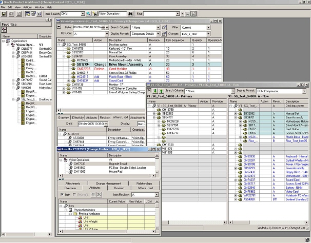
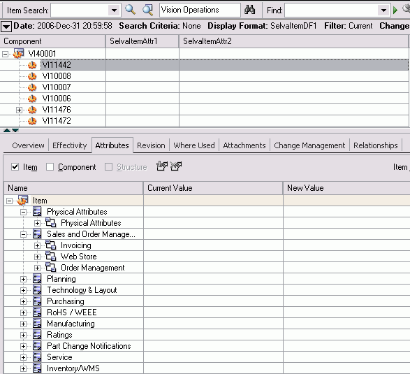
The search results are displayed as nodes under the organization name in a hierarchical format. These results can be sorted on item number or description. Structures created for an item get listed when the node corresponding to the item is expanded. If the user changes the selection in the search results, the item information being displayed in the details window changes appropriately.
Search Results
Viewing and Editing Item Information
Users can view and modify item information in Oracle Product Workbench based on their privileges on this information. The item information is organized on the following tabs in the ‘Details’ window:
Overview Tab
Item Number, Current Revision, Description, Long Description, Primary UOM, Item Catalog category, Lifecycle etc for the selected item are displayed. Select the icon in the attribute tab to show the complete information.
Users with editing privileges can edit the description and long description of the context item. Users can also navigate to html item information pages by clicking the hyperlink against the item number.
Overview Tab
Attributes Tab
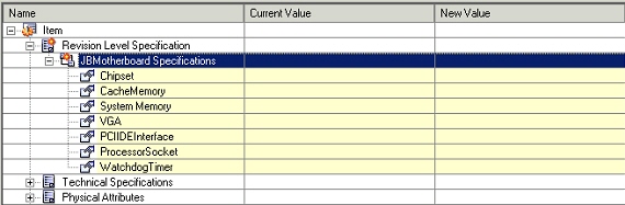
This tab shows the item attributes (both seeded and user-defined) in a hierarchical view under the “Item” node. Different Item attributes are grouped under an attribute group, multiple attribute groups are grouped under an item page, and different item pages are listed under the item node. An Item revision context switcher is provided on this tab to enable users to view the revision level attribute values for the selected revision.
Only those attribute groups are shown on which the user has at-least view privilege. The revision level attribute groups, org-controlled attributes, multi-row attribute groups and the attribute groups under change control are visually indicated through different icons against the attribute group node.
Attributes Tab
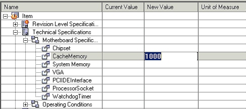
In-place editing of attributes is supported in product workbench. Double click on an attribute value to modify the same. Based on the value set attached to the attribute, the values that the user can specify are restricted.
On modification, the values are not directly saved; they are retained in the markup mode (as per the color scheme configured on a per user basis) and the user can save these changes directly or through a change order based on the change policies.
Editing attribute values
Item attributes cannot be edited in any of the following scenarios:
-
Master Org controlled attributes in Child organizations
-
User does not have edit privileges on the attribute group.
-
Attribute changes are not allowed in the current lifecycle state of the item as per the change policy.
These attributes are indicated with a yellow background. Double clicking on the field will not change the field to the edit mode.
Item attributes that cannot be edited
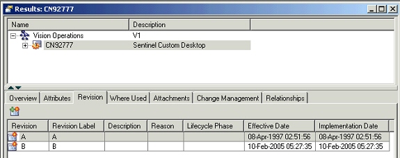
Item Revisions Tab
All revisions that have or have not been implemented are listed on this TAB. Users with appropriate privileges can also create new revisions for the selected item.
Item Revisions tab
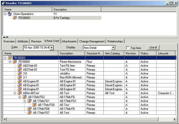
Where Used Tab
An imploded list of all the assemblies using the selected item as a component is shown on this TAB. Users can view the where-used report for a an implosion date/unit number different from the defaulted ones by selecting the values appropriately.
Display format has been seeded to restrict the attributes shown in the report.
Top item check box is provided to show only the end assemblies (without the hierarchy) in this report.
To open the structure in a new window, select an assembly in the where-used report and right click on the “open” /”open with” menu option.
Item Where Used tab
Item where-used functionality supports components of End Item Revision effective structure. On a given implosion date, you can check a parent revision against from and to effective revision for the component. If component is effective, the parent will be included in the item where-used tree. For a component of a fixed revision parent, the component's effectivity is checked on the end date of fixed revision irrespective of implosion date.
The Current Organization option has a Revision filter that selects first level parents having the selected revision of the component as fixed revision. After the first level, implosion will be carried out normally.
The columns Revision and Component Revision in BOM in the where-used table, show the item revision and component's fixed revision in the structure information.
To support Exclusion Rules for where-used, for a excluded component in Product Workbench, the end item from which the component is excluded is displayed in italics.
You can use the Unit option as a filter to control the display on from/to Unit number to support unit effectively.
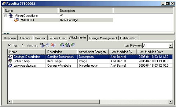
Attachments Tab
An attachment is unstructured information related to an item. For example, unstructured information attached to an item could be a marked up CAD drawing, test results document, specification sheet, or URL.
In the current release of Product workbench only the EBS repository is supported. Product Workbench supports viewing, adding and detaching these attachments.
All the item attachments are listed on this TAB. User can filter these attachments on the basis of item revision by selecting appropriate value from the item revision context switcher.
Adding Attachments
User clicks the appropriate icon to attach a desktop file, text or URL document to the selected item. When a document is being attached, the user can specify an Attachment Category to classify the document.
Viewing Attachments
User can select an attachment from the list and click the View Attachment icon to view the attachment in a new window.
Detaching attachments
User can select an attachment from the list and click the Detach icon for the document that needs to be detached.
Viewing the attachment list in HTML
User can click on the View attachment list icon to launch the list in html workbench. This workbench also lists the Oracle Files (OF) as well as the EBS attachments.
Item Attachments tab
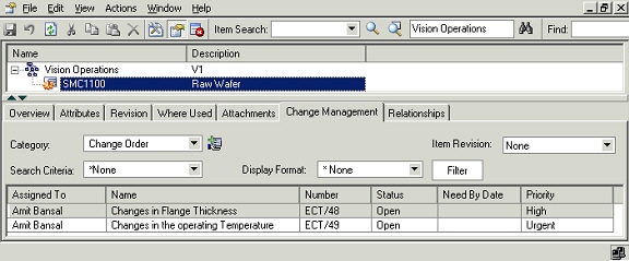
Change Management Tab
The Change Management tab lists the pending change objects for the selected item. The user can view only those change objects on which at-least view privilege has been granted to the user.
Item Change Management tab
-
User can create new changes for change order and issue based categories from this TAB.
-
User can change the selection in “Change Category” poplist to view the change categories like change orders created for the selected item for the selected category.
-
User can use the Search Criteria to filter the change order by type.
-
User can use Create Change Order icon to create a new change order.
-
User can choose a display format to restrict the columns being displayed in the list.
-
User can sort the list on any one of the displayed columns.
-
User can choose to hide one or more of the available columns on display. User can also unhide a hidden column.
-
Different resize actions are possible on the columns.
-
User can filter the list of issues by selecting a value in the search criteria poplist.
-
User can use the filter to define a filter as well as a right click function.
-
User can filter the filtered results by selecting a value displayed in a column and doing a right click action “Filter”. E.g. If “Assigned To” field is being displayed in the issues list and user selects a value say “Sachin Patel” and does a filter, only those issues are listed that are assigned to Sachin Patel. Filters get progressively applied using this functionality.
-
User can apply additional filters against one or more of the following three change attributes irrespective of whether these attributes are displayed or not:
-
Status
-
Assigned to
-
Priority
-
-
User can view changes created for a specific item revision by selecting appropriate value in the revision poplist. Besides specific revisions created for the item, values “None” and “All” are also available in this poplist.
-
User can double click on an entry in the list of change to launch the change details in html UI.
Relationships Tab
Use the Relationships tab to view the reference designators, component operations and substitute components associated with the structure.
Creating Items
You can invoke the create Item dialog from the main menu or from the favorites window as a right click action. The favorites item window is a non-modal one, which means that you can create multiple items one after the other, without having to wait for the completion of creation of previous or perform other actions in Product workbench without having to close this window. The status of each of the item being created is displayed in the create item dialog.
Note: Items can be created in the item master organizations only. User needs to navigate to the html pages to assign the item to different children organizations. Product workbench doesn’t support item assignment to different children organizations.
Create Item
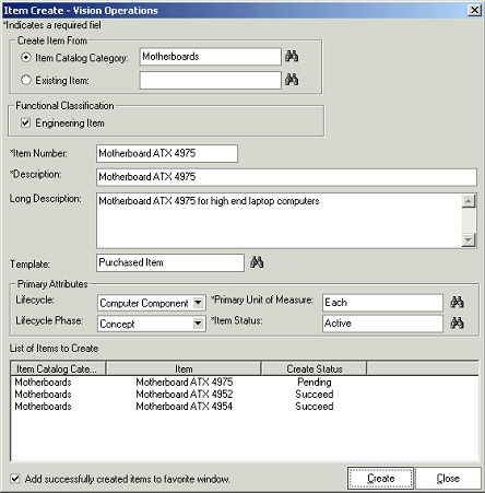
To create items
-
You can provide either an item catalog category (only those item catalog categories that have an item catalog category user role can be selected), or an existing item to create a new item from. If you select an item catalog category, different fields are defaulted as setup for the selection. Examples include Item Number/Description (in case they are sequence generated), item template etc
-
You can choose whether the newly created item is engineering or a manufacturing item by appropriately selecting or clearing the Engineering Item check box.
-
You can then provide the item number, description and long description for the item being created. You can also set up the system for auto numbering.
-
You can optionally choose an item template to be applied while creating the item
-
You can specify a lifecycle or lifecycle phase that the item being created, needs to follow. This is allowed only if the item is being created in a catalog category is associated with valid lifecycles.
-
The Primary UOM and the Item status attribute values are defaulted. You can review these defaults and change them, if required.
-
You can add the newly created items to the favorite list by checking the “Add successfully created items to favorite list”. The items get added to the favorite list as soon as they are created.
Overview of Product Structure and Bills of Material Management
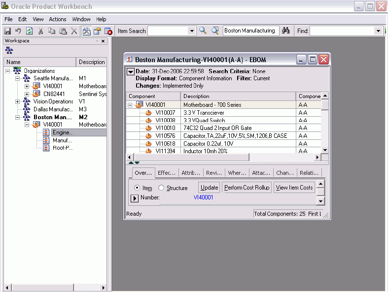
Find Components in Structure
The Product Workbench enables you to quickly Find Components in a Structure. It is text search within the structure window, wherever the text appears, the corresponding item row is highlighted.
Find Components
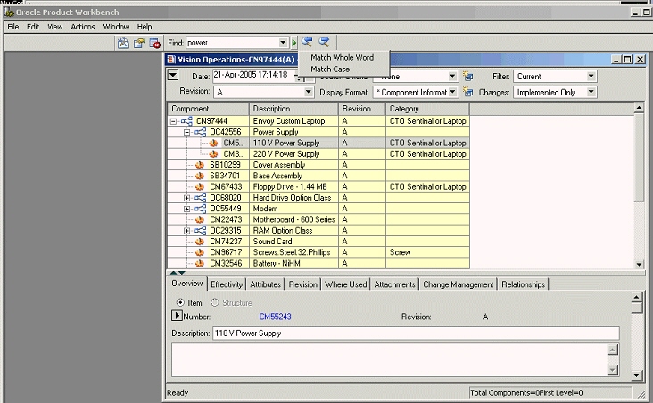
-
For example if you provide the text “power” in the text field to search, all the components containing the word “power” will be highlighted one by one.
-
The navigation to search result is provided by Previous and Next arrow button next to the Find text field. Using this button you view the search results one by one.
-
It also remembers the all the searches that has been done in the past and shows a drop-down menu to select any of those searches.
-
It allows you to perform both case-sensitive and non-case-sensitive searches.
-
It also allows you to match the whole word or partial words from the text.
-
The text is searched within the columns available in the current display formats and search criteria.
-
If there are no components containing the text provided by the user, it shows a dialog indicating no such text has been found in the current structure.
Setting Preferences
The Product Workbench enables you to set preference for various actions. You invoke the preference menu from the Edit top menu.
Preferences
There are four section/tabs for the preference dialog.
General Preference
General Preference enables you to set the general behavior of the Product Workbench Windows client.
General Preference
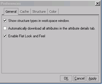
-
You may or may not choose to view the splash screen on start up of the client.
-
You may or may not choose to download all the attribute values in the Attribute tab in the Details section for a structure/search results window. This impacts the first time performance however subsequent view of the attribute details for the item is faster.
-
You can enable or disable the flat "look and feel." This is the default.
Cache Preference
Cache Preference enables you to set the Caching of the data for the performance reason. The data may not be real-time uptime up-to-date, but access to all item/component/structure/change information will be faster.
Cache Preference
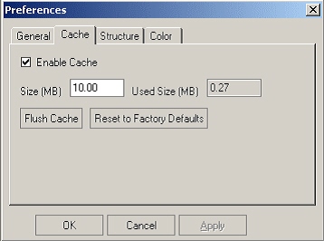
-
You can set the Cache size limit. Cached data are stored in XML files in the user desktop. You can also view the current size of the cached data.
-
You can periodically flush the cached data to download up-to-date information.
Structure Preference
Structure preference enables you to perform column re-sizing in the structure window and control the structure window behavior.
Structure Preference
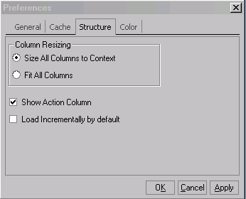
-
You can set preference to size the columns according to its content value size Or Fit the all the columns in the display format to become visible within the window of current size.
-
You can set to reload the structure on the event of changing the drop–downs of any field in the Structure header section like Display format/Selection Criteria/Filter/Changes/Revision/Effectivity etc. Or you can choose to change and explicitly reload the structure by pressing the Go button next the fields.
-
You may choose to hide the Structure header section by default, in the structure window, to have more real-estate in the structure window.
-
You may choose to hide the Action column (which explicitly shows whether the component is Added/Updated/Deleted)
Color Preference
Color preference enables you set different colors for different actions and behaviors. You can set both the background and foreground color for each action and behavior.
Color Preference
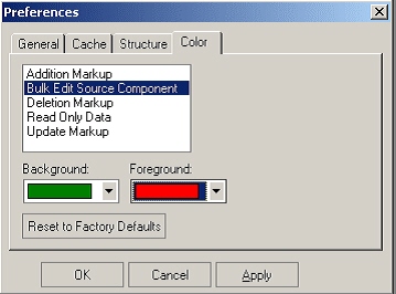
The actions are:
-
Component addition markups could be shown in the color of your choice.
-
Update of Components as markups could be shown in the color of your choice.
-
Deletion of Components as markups could be shown in the color of your choice.
-
Read-Only data, which you do not have access to modify, could be shown in the color of your choice.
-
If you perform Bulk Edit and update the components with the same values, all of them could be shown in the color of your choice.
Managing Bills of Material/Product Structures
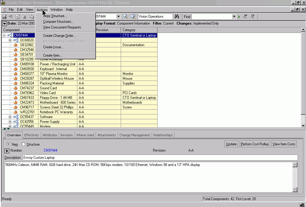
The Product Workbench enables you to work with and manage Bills of Material/ product structures. With the Product Workbench, you can:
-
Perform multilevel structure copy and compare
-
Manage structures using effectivity control
-
Modify structures using the Exclude feature
-
Create structures
-
Edit structures
-
Classify structures
-
Import Product Structures/bill of materials using spread sheet or Item Open interface
For information about Creating Structures, see, To Create Common Structures, in the Bills of Material User's Guide.
Importing Product Structure/BOM
You can use any of the following two methods to import items into the system:
-
Microsoft® Office Excel spreadsheet
-
Item Open Interface
To import product structure using a spreadsheet:
You can use a Microsoft® Excel spreadsheet to import items into the system. Before doing so, you must first have the appropriate version of the Excel spreadsheet installed. Defining of a Display Format is optional if the seeded display formats suite the requirement. Alternately, you can define Display formats to include specific attributes that you would like to export and update. Structure display formats allow you to combine Item operational and user defined attributes, as well as Component operational attributes in one spreadsheet.
You can use the same spreadsheet for multiple uploads, and also across different sessions for the same user. To upload the same spreadsheet during another session, open the spreadsheet you wish to upload, and select Upload from the Oracle menu in the menu bar. After you log in and choose the appropriate responsibility, you can immediately begin to upload this spreadsheet again.
Whenever you enter new or existing data in the spreadsheet, the Upl column displays a flag, making it easier to scan the spreadsheet and for rows that have been changed.
Caution: Item multi-row attribute groups cannot be imported at this time using the Product Structure display formats.
Items uploaded to the system from a spreadsheet become, by default, Engineering items. If you wish to upload a non-Engineering item, then include an available primary attribute column called "Engineering Item Flag" in your display format. When uploading the spreadsheet, identify such items in this column by specifying the value "Yes" or "No" in this column. If you leave the column blank, the item once again defaults to an Engineering item.
You can also assign a default template to the Catalog Category and using the Catalog Category attribute in the spreadsheet you can assign component items to a Catalog Category. While creation of the component Item, the attributes of the default template would be applied to the Item.
Note: Structure import allows you to create new items or update existing items. This greatly simplifies the maintenance of the BOM and the items that make up the product structure.
-
In the HTML Structure pages, choose an assembly item and navigate to the Configurations tab
-
Create a Structure header for creating a new product structures and click the ‘First Level Components’ link
-
On the First Level Components page, select the Display format that you want to use for exporting to Excel. You can personalize a display format if required before exporting.
-
Select Export to Excel in the action drop list. On the Export to Excel page, enter the numbers of levels of the product structure that should be exported. A default value of 60 is already set. This is the maximum number of levels you can enter. Then click Continue.
-
On the Select Settings page, select the version of Excel that you are using and click Next. You cannot enable or disable Reporting. Also, Language has only one choice, which is already selected.
-
A download window presents processing messages. Click Close when the transfer is complete. The Excel spreadsheet also opens.
-
In the spreadsheet, primary attributes are listed first (on the left), and user-defined attributes appear after (on the right). When entering values into the spreadsheet, you must use one of the following Transaction Types:
If the component already exists, the spreadsheet values are used to update it. If the component does not already exist, a new one is created using the spreadsheet values. If the Sync creates a new item, then the mandatory attributes for Create are also mandatory for the Sync. If the Sync updates an existing item, then the mandatory attributes for Update are also mandatory for the Sync.
Sync will also create new component items using the defaults in the spreadsheet if the component items do not already exist.
Note: To delete an existing value in a record, enter the following data in the appropriate column of the spreadsheet:
For field type: Enter value: Date 31-DEC-9999 Character ! Numeric 9.99E125 If you want to retain an existing value in a record, enter NULL in the appropriate column of the spreadsheet.
Exception: In the user defined attributes interface table, when you want to delete an existing value in any of the following fields, use the value !. If you want to retain an existing value in a record, no entry is necessary.
-
ATTR_DISP_VALUE
-
ATTR_VALUE_STR
-
ATTR_NUM_VALUE
-
ATTR_VALUE_DATE
A new item is created using the values entered in the spreadsheet. A new component entry is created using the values entered in the spreadsheet. The following attributes are mandatory when using this transaction type and the component items don’t already exist:
-
Item
-
Organization Code
-
Primary Unit of Measure
-
Description
Note: Description is a primary attribute, but appears on the right side of the spreadsheet among the user-defined attributes. It is placed here so that long descriptions will not disrupt the flow of the spreadsheet.
Make a note of the Result Format Usage ID at the top of the spreadsheet. You will need this ID later when you upload the spreadsheet in the system.
-
-
After data entry is complete, select Upload from the Oracle menu in the toolbar.
-
In the Upload Parameters window, enter the Result Format Usage ID and check the Automatically Submit Concurrent Process box, and then click Proceed to Upload.
-
In the Oracle Web ADI window, click Upload. After the upload process completes, a message appears with the Concurrent Request number. Make a note of this number, as you will need it later when you access the view log for the concurrent request. Click Close when the process messages complete.
-
Return to the Applications tree menu and click the View Concurrent Requests link.
Important: It is recommended that you review the concurrent process view log to ensure that the upload process was successful.
-
On the View Concurrent Requests page, click Details.
-
On the Request Details page, click View Log.
-
Here two requests are launched; one for defining the component items if new items have to be created, or any items have to be updated. The second is for processing the product structure. Both requests must be completed successfully for the structure to be created or updated.
-
From the View Log, paste the URL string in a web browser to view any errors. If no errors appear, the upload was successful.
Attributes of existing item and component will be updated to the values in the spreadsheet. If an Item does not exist or a component does not exist, the import process will fail with an error.
Often times the Items in the system are reused in different assemblies. To create product structure by simply adding already existing items you can use a transaction type of Add. This does not create any items or will not update any item attributes, even if the values in the spreadsheet are changed. The assumption with using this transaction type is that you are reusing the items and that the item attributes are not being changed. If you wish to do so either use the transaction type of Sync or Update.
To import product structure using Item Open Interface:
This topic discusses the availability of multilevel Copy API for copying a structure. You can copy structures within an organization or across organizations. When you import items through the Item Open Interface, you create new items in your item master organization, update existing items, or assign existing items to additional organizations. You can specify values for all the item attributes, or you can specify just a few attributes and let the remainder default.
The Open Interface program validates all data before importing it into the production tables.
-
Use oracle.apps.bom.structure.copy.server.BomCopyStructureAM to copy single or multilevel structures.
-
Load the Item Open Interface table (MTL_SYSTEM_ITEMS_INTERFACE) with the data you want to import.
-
Navigate to the Inventory Responsibility in Oracle Applications, and click the Inventory link. Then click the Items link.
-
Click the Import link.
-
Click the Import Items link
Note: The Parameters form automatically appears when you select a request that requires parameter values.
-
Enter the required values in the parameter fields
-
Click OK and then click Submit
Using Multilevel Structures
Multilevel structures, or indented structures, enable you to view all component levels of an item, through multiple levels of subassemblies to the raw materials. You can also view multilevel structures across multiple organizations, copy, and compare them.
To use multilevel structure copy
Performing a structure copy is a productive way for reusing existing structures to define new structures for an item. Copying a multilevel structure enables you to create a new structure or to copy specific subassemblies to any level of a multilevel structure within the same organization or across multiple organizations.
For example, you can manufacture an item in different organizations than the engineering organization. You can copy past, current and future item revisions to other organizations. If certain engineering components are not enabled in the other organizations, they are enabled as part of the copying process.
This functionality can improve your organization's efficiency by enabling the copying of items and their structures across multiple organizations.
-
Select item with the context organization. You can view the common structure information. Note that the shading indicates common structure information.
-
From the Actions menu select Copy Structure. You can also use the right click to select copy structure from the Structure menu item.
-
Enter the Copy From (source) structure information to be copied in the left pane. The selected item is defaulted. Optionally you can select any item manually. Enter the Copy to (target) structure information in the right pane which indicates the components or structure to be copied.
Structure information includes:
-
Organization
-
Item
-
Revision
-
Structure Type
-
Structure Name
-
Engineering - engineering structure or manufacturing structure.
-
Effectivity Date (based on the type of effectivity control whether date or serial number or model/unit number), this field is appropriately rendered.
-
Filter (Current, Current and Future or All)
-
Changes
-
-
The target structure type and name is a filtered list for only the empty/new structure of the target Item.
-
In the target structure, you can optionally provide structure description.
-
If you select the Unchecked check box next to Engineering, this will indicate that the structure is to be used in Engineering and the field changes to Checked.
-
Select the Next button, and the Copy Structure: Select Organization form appears.
-
Select one of these options:
-
Master Organization: Select this option to include all items in all levels of the master organization.
-
Organization Hierarachy: Select this option to include a specific level within your organization.
-
-
Select the check box next to the organization from which you want to copy a structure.
Right-click in the check box column to Select all or Deselect All organizations.
-
Optionally, select the Common Structure and Engineering check boxes for the organization from which you want to copy a structure.
The Common Structure check box creates a common structure based on the target structure in the selected organization and assigns the items to the organizations if they do not exist.
The Engineering check box enables you to set the engineering type for the structure in the selected organizations. If the source structure is a manufacturing structure, you can choose to copy the source structure to a manufacturing or engineering structure.
-
Click the Next button, and the Copy Structure form appears. The Copy Structure form displays:
-
All of the organizations that the copy/common function will use
-
The components and sub-assemblies for the structure revisions for the components
-
The current item assignment
-
The organizations in which new item assignments will be made, for each component
-
The organizations in which the structure current exists
-
The organizations in which the component or subassembly will be copied to
-
The organizations that the component or subassembly currently is common in and the organizations that they will be common in after the copy
-
-
Complete selection of release options for end Items and sub-assemblies.
Double clicking on a component row will bring up the Component Option form. You can use this form to control each organization at a the component level. For example you can control how the component in each organization will be managed during the copy. Unchecking the options (which vary on the copy options selected) will exclude operations on the component during the copy.
-
Click the Copy button. A popup menu appears, and you can chose from the following options:
-
Copy in Place
-
To the New change Order
-
To an Existing Change Order
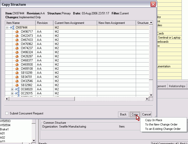
-
-
(Optional) Select the Submit Concurrent Request check box if you want to perform the copy structure process immediately. If you select Submit Concurrent job checkbox and select the copy, you get the three options: Select Copy button, Choose from options (the option will determine how the copy operation will be processed) and Copy In Place which will create a concurrent request. The other two will allow you manage the copy through a new or existing change order.
If you do not check the Submit Concurrent job check box and select copy, then you have the three options as before. If you choose copy in place the system proceeds with the copy.
-
Click the Copy button.
-
Copy In Place generates concurrent request and errors and details reports.
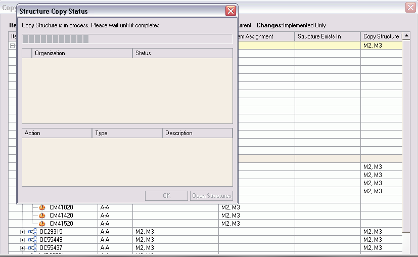
The structure will be copied and the new structure window will open.
Note: Structure is copied immediately and it does not create a redlined BOM.
The structure is also copied in place and can be added to a new or an existing change order.
When the source structure is copied into the target structure, the source component revision must be valid for the target parent item revision.
If the target structure name is available in the sub-assemblies, all the sub-assemblies, their hierarchies and components will be available in the target structure as well.
The effectivity of the components are created according to the value as given by the user in the copy dialog.
To use multilevel structure compare
Product Workbench’s feature-rich graphical user interface allows you to perform a side-by-side comparison of structures across multiple organizations. You can compare two structures of the same item, two structures of different revisions of the same item, or compare structures of two different items, all accomplished by using the source and target structures you have selected for comparison in the same interface.
To compare two structures, either click the Compare Structures menu from the Action menu, or select a structure, right-click and then select Compare Structure as a context action.
Select Structures to be Compared
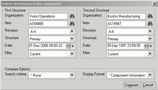
-
Enter the Source Structure information for which comparison needs to be done in the left pane and the target structure information with which the comparison will be done. Structure information includes:
-
Organization
-
Item
-
Revision
-
Structure Name
-
Filter (Current, Current and Future or All)
-
Effectivity Date (based on the type of effectivity control whether Date or Serial number or Model/Unit number, this field is appropriately rendered
-
Compare Options
-
Search Criteria
-
Display Format
-
-
-
Specify the search criteria (BOM filter) and display format (all the columns you want to see in the comparison results window) for the structure.
-
Click Compare button in the dialog to view the results. Depending on the size of both structures, this may take some to time to display the results.

The overall difference summary is shown in the status line indicating how many components have been added/deleted/changed between the two structures.
The differences between the two structures are visually indicated according to the difference For Example, components that exist in one structure only are indicated in blue.
-
When comparing structures, you can easily browse through the next and previous differences between the two structures using the Previous and Next icon/button on the top of the window.
Expanding a node in the source structure will automatically expand the corresponding node in the target structure to maintain a one to one correspondence between the levels of the two structures being compared.
-
You can also change the comparison criteria for the source and target structures you have selected earlier in the results window, as well using the collapsible hide/show section in the top part of the results window.
Managing Structures Using Effectivity Control
You can manage product structures using the following effectivities:
Date Effectivity allows you to create structures in which components are effective based on dates. You can create and view date effective structures in Oracle Product Workbench.
Revision Effectivity allows you to create structure in which components are effective based on revisions of the parent item. During the concept & design/development phases of a product, revision effectivity is generally used for configuration management of engineering product structures. Revision effectivity, controls the effectivity of the components relative to its parent item’s revision. You can create and view revision effective structure in Oracle Product Workbench. In the Design cycle, users can maintain the Product Structure by Revision Effectivity such that the components of an Assembly can be made effective using revisions of the Assembly. This features allows users to clearly define the components specific to the revision of the parent without having to know the dates of the parent item's revision. For example, Engine has Revisions 001 and 002:
Piston (Engine.001 - Engine.001)
Piston1 (Engine.002 - )
Shaft (Engine.001 - )
This shows that users can phase in/phase out the components by simply giving the revision of the parent.
Important: Revision Effective structures cannot be defined for manufacturing (released) BOMs, but only for Engineering BOMs or for Items in an Engineering Phase. This is a design time usage feature only and is not supported by Manufacturing, Planning etc. downstream applications.
Note: You can use change control with revision effectivity.
Unit Effectivity allows you to create structures in which components are effective based on Model/Unit Numbers. You can view and edit unit effective structures in Oracle Product Workbench.
Serial Effectivity allow you to create structures in which components are effective based on serial numbers. You can only view serial effective structures in Oracle Product Workbench.
Excluding Structures
A structure contains information on the parent item, components, and optionally, attachments and descriptive elements. You can modify a structure using the Exclusion feature. You can create an engineering or manufacturing structure by manually defining all of the components for the structure, or copying from an existing structure, or referencing another structure.
Sometimes minor changes need to be made to existing structures to meet business needs. In Product workbench, you can use an existing bill and define minor variations in the bill through the exclusion feature.
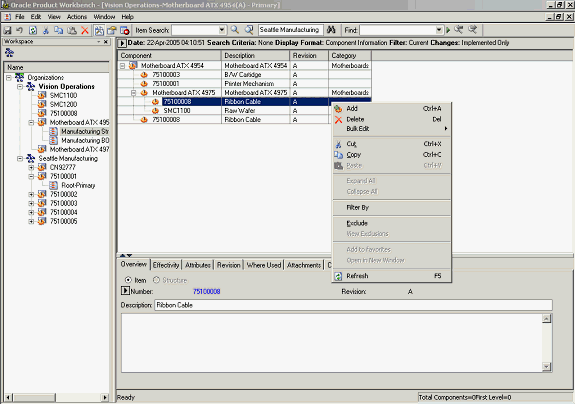
To exclude a component from a bill:
-
Select an item from the Favorites list, and launch its bill.
Launch Bill
-
Highlight the component to be excluded from the bill, and launch the Exclude action from the right click menu.
The structure is displayed in markup mode, with the excluded component highlighted.
Excluded Components
Note: You cannot exclude components in a bill that is common to another (source) bill.
-
Save your work.
You will be prompted to refresh in order to re-explode the bill to reflect all the changes to the bill. Click Yes
Save and Refresh
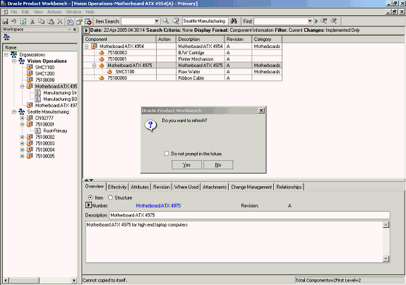
The Bill is displayed without the excluded component.
Note: The scope of the exclusion is restricted to the structure of the top item in the structure window.
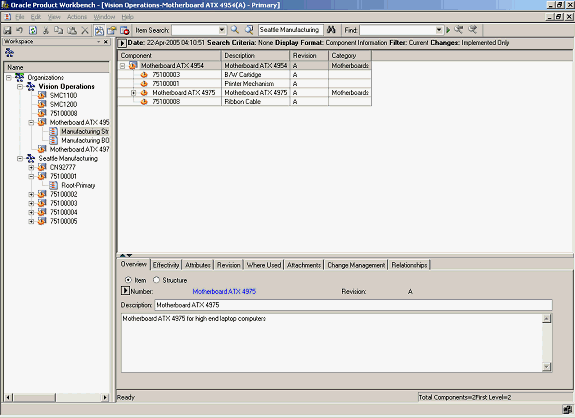
Thus in the above example, item#75100008 is excluded from the primary structure of the top item in the window (item#Motherboard ATX 4954). But, if you separately launch the structure for item(sub-assembly)#Motherboard ATX 4975, item#75100008 would continue to be shown in the structure of the sub-assembly. In other words, the scope of the exclusion is restricted to the primary structure of the top item in the structure window and is not applicable to intermediate sub-assemblies.
To view, hide, or remove structure exclusions
-
Launch the structure of the item whose exclusions you want to view.
-
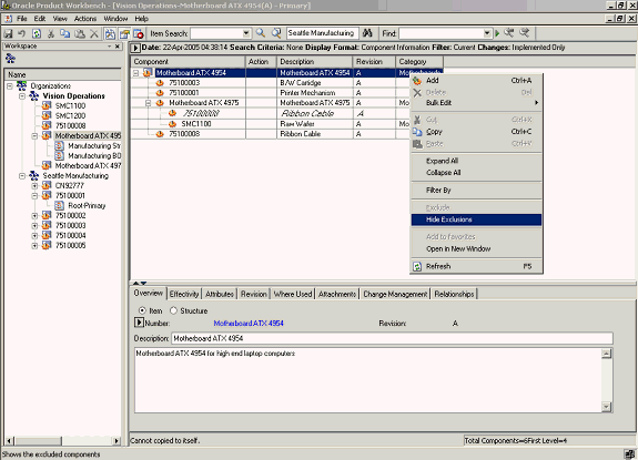
Select the top item in the structure and launch the View Exclusions action from the right click menu.
Note: You cannot use Expand all. If you have an excluded component at a lower level, explode parent subassembly by manually expanding the parent node to enable View Exclusions.
View Exclusions
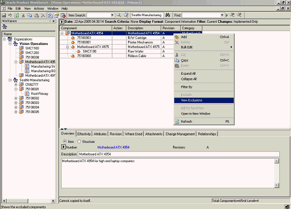
-
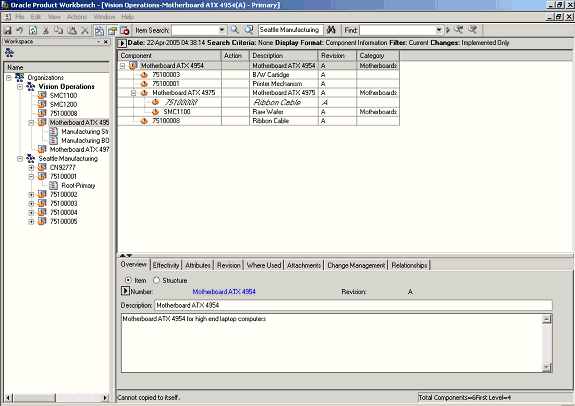
The structure is displayed with all the excluded components suitably highlighted.
Excluded Components
-
You can hide the exclusions by highlighting the top item, and then launching the Hide Exclusions action from the right click menu.
-
You can remove exclusions that have been previously defined for a structure. Highlight the top item and view exclusions defined for the structure of the item (as described previously). Select any exclusion and launch the Remove Exclusion action from the right click menu.
Hide Exclusions
Remove Exclusion
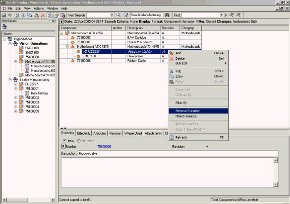
-
The structure of the top item is displayed in mark up mode with the previously excluded component appearing again in the structure of the top item. Save your work. You will be prompted to refresh the window. Click Yes.
The component which was excluded from the structure of the top item previously is now included in the structure.
Using exclusion rules components can be excluded/included at any level in the product structure with effectivity relative to an end item. This allows you to define different configurations for the same end item using different components rather than defining/maintaining multiple product structure definitions for variants of the end item. You can choose to hide or view excluded components when viewing a product structure. You can remove the exclusion rule on a previously excluded component. Exclusion rules are specific to an end item, which allows you to reuse the same subassemblies with different configurations in different products
Exclusion Rules by Product Revisions
The system enables you to exclude components from specific revisions of end items.
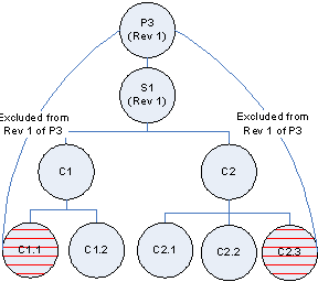
Example: Exclude Components from a Specific Revision of an End Item (Product)
For Product P3 Components C1.2 from subassembly C1 and C2.3 from subassembly C2 have been excluded. Now if the user creates a new revision 2 of Product P3, the exclusion rules are automatically excluded from this new revision. The user can further exclude more components from revision 2. Specific component revisions will not be excluded from the end item revision.
| Parent | Child Component | Effective From | Status | Effective To |
| P3 | S1: Rev1 | P3: Rev1 | ----------- | |
| S1 | C1 | S1: Rev1 | ----------- | |
| S1 | C2 | S1: Rev1 | ----------- | |
| C1 | C1.1 | C1: Rev1 | Excluded P3: Rev1 | ----------- |
| C1 | C1.2 | C1: Rev1 | ----------- | |
| C2 | C2.1 | C2: Rev1 | ----------- | |
| C2 | C2.2 | C2: Rev1 | ----------- | |
| C2 | C2.3 | C2: Rev1 | Excluded P3: Rev1 | ----------- |
Pictorial view for structure for Revision “1” of product “P3”
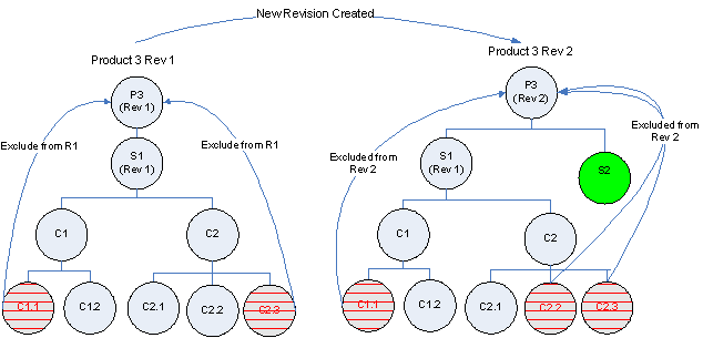
A variation of product P3 has the following differences with reference to the structure for Revision 1 of product “P3” as shown above:
-
Additional Component S2 as immediate child component
-
Component C2.2 (P3: Rev 2>S1>C2>C2.2) has been excluded
To achieve this configuration, do the following:
-
Create Revision “2” for the end item “P3”
-
Exclude Component C2.2 from Revision 2 of Product P3.
-
Add Component S2 with effect from revision “2” of end item “P3”.
The following table and pictorial show data for the structure for revision “2” of product “P3”:
| Parent | Child Component | Effective From | Effective To | Status |
| P3 | S1: Rev1 | P3: Rev1 | ----- | |
| P3 | S2 | P3: Rev2 | ----- | |
| S1 | C1 | S1: Rev1 | ----- | |
| S1 | C2 | S1: Rev1 | ----- | |
| C1 | C1.1 | C1: Rev1 | ----- | Exclude- P3:Rev2 |
| C1 | C1.2 | C1: Rev1 | ----- | |
| C2 | C2.1 | C2: Rev1 | ----- | |
| C2 | C2.2 | C2: Rev1 | ----- | Exclude- P3:Rev2 |
| C2 | C2.3 | C2: Rev1 | ----- | Exclude- P3:Rev2 |
Pictorial view for differences between structure for different revisions of product “P3”
Excluding Transaction Attribute Value Set Values
You can use transaction attributes to assign item characteristics during an item transaction rather than at the time of item creation. However, there are times when you might want to exclude a particular attribute value from possible assignment. The following scenario provides an example of a transaction attribute value exclusion.
Bundle Product Promotion Offer
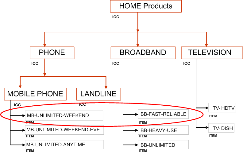
The following graphic shows two items, a cell phone package and broadband internet access, that a telecommunications company wants to sell as a bundled item to consumers. The company bundles to encourage customers to buy more items in total. Because the price of the two items bundled together is less than if the items were sold separately, the company wants to exclude two of the more expensive options from the bundle's structure. Normally, customers could choose from the following four cell phone colors:
-
Red
-
Blue
-
Green
-
Metallic
However, the metallic finish is more expensive than the others, so this attribute value, metallic, is excluded from the promotional offer bundled item only. If a customer wants a metallic phone, they can still order it, but not as part of the bundle.
One of the broadband internet access options is upload speed. Normally, the choices are:
-
2 megabytes per second (Mbps)
-
4 Mbps
-
8 Mbps
-
10 Mbps
When purchasing the bundle, though, the attribute value of 10 Mbps is excluded.
Overall Product Model
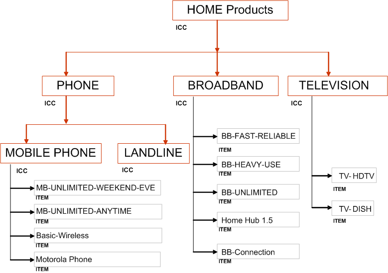
Phone-Internet Bundle
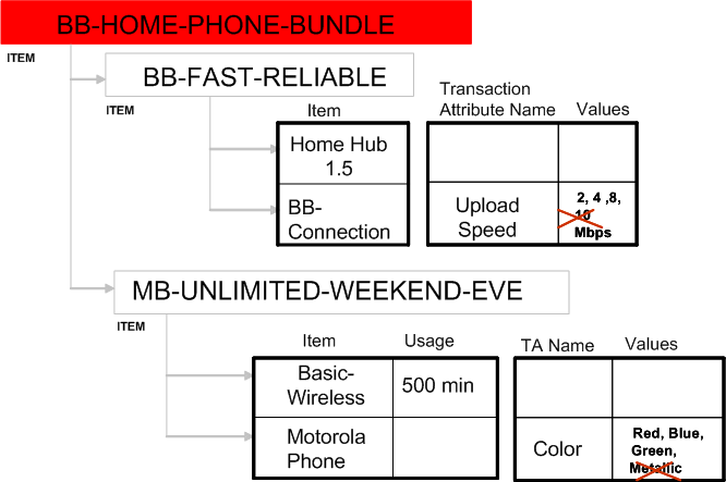
The transaction attribute values excluded only apply to one specific end item structure and for one specific instance of the item’s usage in the end item structure. The following examples help explain this concept.
Exclusion Behavior Examples
-
You can exclude 10 Mbps from BB-CONNECTION in the structure of BB-HOME-PHONE-BUNDLE shown above. 10 Mbps still appears in the list of transaction attribute value choices if BB-CONNECTION appears as part of another end item's structure, though.
-
If the same item with the excluded value is included in another structure of the same end item or in another structure of another end item, then the value is not excluded.
-
Exclusions have no effect across organizations. For example, if you exclude a value from a structure in the V1 organization, then copy the structure to the M1 organization, the value is no longer excluded in the M1 organization.
-
Once you delete the item with the excluded value from the structure, the exclusion is lost. For example, exclude 10 Mbps from the item BB-CONNECTION shown above. Now delete the item BB-FAST-RELIABLE from BB-HOME-PHONE-BUNDLE. Add the item BB-FAST-RELIABLE back to BB-HOME-PHONE-BUNDLE. Drill down to BB-CONNECTION; 10Mbps is no longer excluded.
Important: You can only exclude transaction attribute values from structures created in the Product Workbench with the following parameters:
-
The Engineering box is selected.
-
The structure name is something other than Primary.
-
In the Effectivity field, Revision Effectivity is selected..
-
The attribute value set's validation type is either Independent or Translatable Independent.
You cannot exclude transaction attribute values from structures created using Oracle Bills of Material, the Microsoft Excel import process, the Import Workbench, or the Open Interface tables. When you add a component to a structure, the component is in markup mode and you cannot exclude transaction attribute values. You must save the structure after adding components before you can exclude values.
Prerequisites
- You must have a role that includes the Edit Transaction Attribute privilege for the end item (the top level item in the structure) in order to exclude a transaction attribute value for an item in the structure.
To exclude a transaction attribute value
-
Navigate to the Product Workbench. Search for and select an end item from the favorite items list or from the item search results.
-
Select one of the end item's non-primary structures. Right click and select Open to view the end item's structure.
-
Select the component for which you want to exclude a transaction attribute value.
-
In the tabbed region below, select the Attributes tab, then the Item checkbox.
The list of attribute groups for the component appears.
-
Drill down into the transaction attributes and select the attribute value that you want to exclude.
-
Right click on the attribute value to exclude and select Exclude From, then either:
-
Current Revision Only
-
Current Revision Onward
This excludes the current revision as well as all revisions valid in the future.
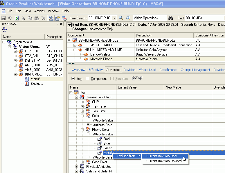
Once you exclude an attribute value, the value appears in red text with a line through it (strikethrough text).
-
-
Click Save.
To unexclude a transaction attribute value
-
Right click on the attribute value to unexclude and select Remove Exclusion, then either:
-
Current Revision Only
-
Current Revision Onward
The value now appears in plain black text.
-
-
Click Save.
Overriding Component Attribute Values
Component attributes apply to the relationship between a parent and a component item for a specific structure type. All structures of the same structure type have the same component attributes available to them between any level of parent and component items in the structure. A component item could have multiple parents in the same item structure. If this is the case, the component attributes for the component can have different values for each unique parent child relationship since a component attribute is specific to the relationship between a component item and its immediate parent item.
The Product Workbench enables you to override a component attribute value for a component item in a parent child relationship within the context of a specific end item (top assembly item) and only for a specific instance of the relationship. If you use the same parent child relationship in another structure, then the component attribute values remain the same as they were when originally set within the relationship between the component and its parent item. You can choose to override a component attribute value for the current revision of the end item only or for the current and future revisions, You can also remove an override at any time. If you remove an override, the original component attribute value becomes effective. The following scenario provides an example of overriding component attribute values.
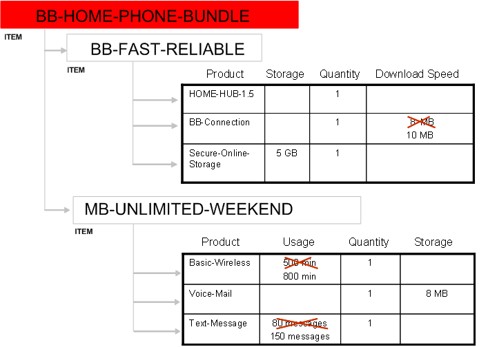
Bundle Product Promotion Offer
The following graphics show two items, a cell phone package and broadband internet access, that a telecommunications company wants to sell as a bundled item to consumers. The company bundles to encourage customers to buy more items in total. The company gives customers better features on the bundled items than they do when selling the items separately. In this case, if you buy the bundle, you get 10 MB of internet download speed instead of the usual 8 MB, 800 minutes of cell phone usage instead of the usual 500 minutes, and 150 text messages instead of the usual 80.
Overall Product Model
Phone-Internet Bundle with Overrides
Prerequisites
- Optionally, create a display format for the structure type of the end item's structure that includes the component attributes. See: Defining Display Formats and Search Criteria for Structures, Oracle Product Information Management Implementation Guide
- Ensure that you are working within a revision effective structure. You can only override component attribute values within revision effective structures.
- When adding a component to a structure, save the structure before overriding component attribute values.
When you add a component to a structure, the component is in markup mode and you cannot override component attribute values. You must save the structure after adding components before you can override values.
To override a component attribute value
-
Navigate to the Product Workbench. Search for and select an end item from the favorite items list or from the item search results.
-
Select one of the end item's structures. Right click and select Open to view the end item's structure.
Tip: If you have a display format that includes component attributes, then select the Open With option. In the Open With... page, select the display format you want to use. If the component attributes are visible in the upper page view, then you can override their values from there as well as from the lower page view.
-
Select the component for which you want to override a component attribute value.
-
Override the current component attribute value.
You can override the value in either the upper or lower page view.
Important: You cannot view multi-row component attributes in the upper page view, so you must enter multi-row component attribute override values in the lower page view.
To override the value using the upper page view
-
Right click in the component attribute field.
The Specify Component UDA OverrideValue window appears.
-
Double click in the Override Value field and enter the override value.
Note: You can use the Actual Value field in this window to change the component attribute value in all instances of this lowest level parent child relationship. This has the same effect as if you double clicked on the field and changed the value. See: Editing Structure Information.
-
In the Version field, select either:
-
Current Revision Only
-
Current and Future Revisions
This applies to the revision level of the structure's end item.
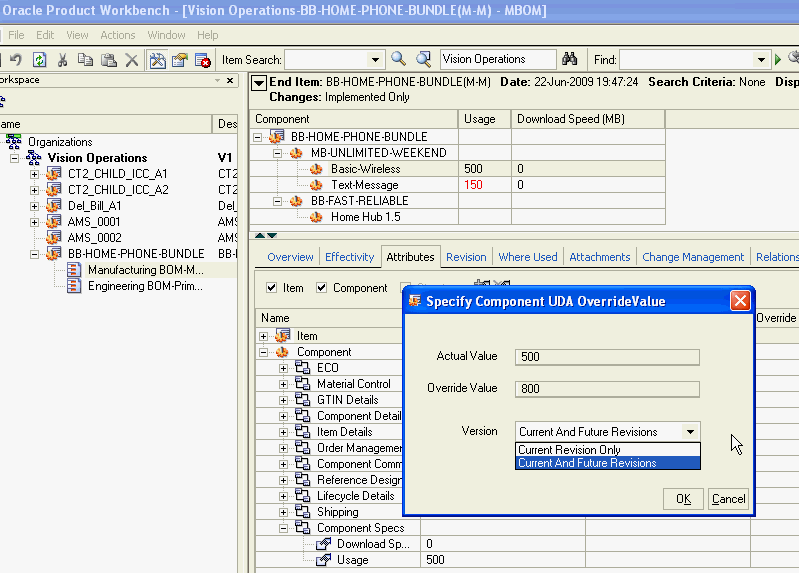
-
-
Click OK.
To override the value using the lower page view
-
In the lower page view, select the Attributes tab.
-
Check the Component box.
-
Find the component attribute group that contains the component attribute values that you want to override. Expand the attribute group name so the component attributes are visible in the Name column.
-
Click on a component attribute to select it, then double click in the Override Value field.
The Specify Component UDA OverrideValue window appears.
-
Double click in the Override Value field and enter the override value.
-
In the Version field, select either:
-
Current Revision Only
-
Current and Future Revisions
This applies to the revision level of the structure's end item.
-
-
Click OK.
Once you enter an override value, the value in the component attribute field appears in bold red text in the upper page view. In the lower page view, the value appears in the Override Value field, while still showing the original value in the Current Value field.
-
-
Click Save.
After saving, the the value in the component attribute field appears in regular red text in the upper page view.
-
You can only view component attribute override values from the end item structure. Using the example above, if you enter the component attribute override value of 10 MB for the component BB-Connection, you can only view this value from the structure for BB-HOME-PHONE-BUNDLE, not from BB-FAST-RELIABLE.
-
Since component attributes are organization specific, the override values are organization specific, also.
-
When you view the end item structure in Oracle Applications HTML pages, for example, in the Structure: (structure type) page, a new column appears next to the overridden component attribute column. For example, if the component attribute column name is Download Speed, the override column name is Download Speed_OVD.
-
You can export the structure with override values from the Structure: (structure type) page. From the Actions drop down menu, select Export to Excel. You cannot change the override values in the Excel spreadsheet; an error message says that the cells are read-only.
-
To remove an override value
-
In the upper page view of the structure, select the component.
-
Right click on the component attribute value field, then select Remove Override. Choose either:
-
Current Revision Only
-
Current and Future Revisions
Alternatively, in the lower page view of the structure, you can double click on the Override Value field. In the Specify Component UDA OverrideValue window, double click on the Override Value field and delete the value.
-
-
Click Save.
Creating Structures
A structure contains information on the parent item, components, attachments, and descriptive elements. Each standard component on a structure can have multiple reference designators and substitute components.
User can create either an engineering or manufacturing structure, copy an existing structure, associate an ICC structure, or reference a common structure. When a user creates a structure, it exists only in the current organization. To use a structure in another organization, user must either copy it or reference it as a common. User can create structures for only those items on which the user has edit privileges.
All types of bills (standard, model, option class and planning) except the product family bills can be created in product Workbench. Date, revision, and unit effective structures can be created. Creation of serial effective structure is not supported in the current release of Product Workbench.
To create a structure
-
Select an item from favorite items list or from item search results and invoke the create structure dialog through the right click ‘create structure’ action.
Create Structure
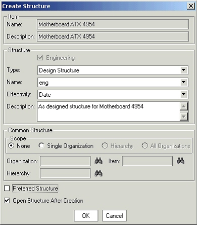
-
If the selected item is an engineering item, the Engineering check box will be selected and cannot be edited. In case of a manufacturing item, user can choose to create a manufacturing or engineering structure.
-
Select a structure type and a structure name. Only those combinations are available for which a structure doesn’t already exist for the selected item.
-
Specify the effectivity control for the structure being created. Choose from date or revision effectivity.
Note: Revision effective structures are always of type Engineering.
-
Provide a description for the structure.
-
Choose whether the structure being created is a preferred one for the selected structure type.
-
Check the Open structure after creation if you want to continue editing the structure.
-
Click the OK button. This will open up the new window where the user can specify other information related to the structure. The structure is not yet saved.
Newly Created Structure
-
Select the top node, right click, and select Add in the structure window to open the Add Components window. You can also open the Add Components window by dragging and dropping an item from the favorites list, item search results or from another structure window.
Add Components
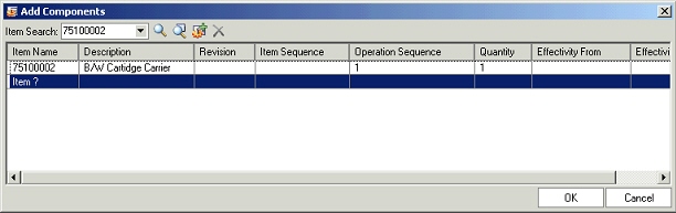
In the Add Components window, add one or more components to the node selected in the structure window through the following actions:
-
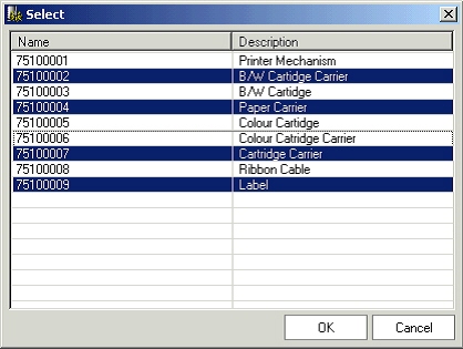
Perform item simple search by providing the complete or partial item number/description and clicking on the simple search button. In case of a single match, the item gets automatically selected in the Add Components window. In case of multiple matches, a new window showing all the search results is shown and the user can select one or more items from this window:
-
To select a set of adjacent rows, select the first row and hold down the shift key and select the last row to include.
-
To select non-adjacent rows, select a row or a range of rows and then hold down the Ctrl key and keep selecting the rows to include.
Selecting Items for adding as components from the simple search results
-
-
Perform an advanced parametric search and add one or more items from the search results.
-
Create new items and add them as components.
-
Provide the complete or partial item number in a new row in the Add Components window, by double clicking on in the Item Name column. Behavior is similar to the simple search described above.
Note: You can only select valid components in the Add Components window. Refer to the Bill of Material User's Guide for these dependencies.
-
-
Review the components selected in the add component dialog and make necessary changes. The changes that can be done are as follows:
-
Use a fixed component revision instead of floating (default behavior). Users can better manage design configurations with Fixed or Pre-specified revision. During a design phase, subassemblies may go through rapid changes and the consumers of the subassembly can shield themselves from these changes by fixing the revision of the component subassembly until they choose to change it. In case of certain subassemblies, engineers of the consuming subassembly may always want to pick the current revision of the subassembly. A fixed component revision caters to both usages.
Important: Consuming applications like WIP, APS, MRP,etc EBS applications do not support Fixed Revision of the Component. Manufacturing BOMs therefore cannot have components with a fixed revision.
-
Specify an item sequence and/or an operation sequence
-
Modify the default quantity of 1
-
Modify the effectivity range i.e. start and end date in case of a date effective structure and a start and end revision of the parent for revision effective structure.
-
Remove one or more items selected in the add component dialog.
-
-
Click the OK button to add the selected components to the node selected in the structure window.
-
Repeat steps 9-11 for adding components to lower level subassemblies to create a multi-level structure.
-
Optionally specify reference designators, substitute components and optional routing operations for applicable components in the structure.
-
Review and modify the structure information i.e structure/component attributes, attachments, effectivity etc as per requirements and save the structure in place or on a change order.
To associate an ICC structure with an item
If an item belongs to an item catalog category with an associated structure, you can associate this ICC structure with the item. ICC structures are useful when many of the items within an item catalog category use a similar structure. After associating an ICC structure with an item, you can add components, but you cannot edit or delete components or component attributes from the item's defaulted ICC structure.
Tip: You can delete components from the item's defaulted ICC structure in theStructure: (Structure Name) page, but to add components, you must use the Product Workbench. See: To associate an ICC structure with an item.
For more information about ICC structures, see Creating an Item Catalog Category Structure, Oracle Product Information Management Implementation Guide.
-
Follow the steps described above in "To create a structure:"
-
In order to associate an ICC structure with an item, specify the following during the structure creation process:
-
Verify that the item is an Engineering item.
-
Select the same structure type and structure name as the ICC structure.
-
Select revision effectivity control.
If the system finds an ICC structure to associate, you receive the message "Components inherited from Item Catalog Category exist for this Structure. To view the inherited components, please save the Structure.".
-
-
Save the structure.
You can now add components to the structure if you choose as described in "To create a structure:".
To create common structures
If two or more organizations manufacture the same item using the same bill of material, user can define the bill in one organization and reference it from the other organizations. Necessary changes must then be made to the referenced bill. This greatly reduces the effort involved in maintenance of the structure information by centralizing the controls.
Optionally, you can reference all but the following five fields in a bill, maintaining these fields by individual bill of material:
-
Supply Type
-
Sub Inventory
-
Locator
-
Operation Sequence
-
Include in Cost Rollup
The following notes apply while creating common structures:
-
User cannot reference another structure as a common if that structure also references a common. In other words, user cannot create a chain of common references.
-
User can only reference another structure as a common if it has the same structure name assigned to it.
-
If the current structure that a user is creating is a manufacturing bill, the common bill must also be a manufacturing bill.
-
User can only reference bills from organizations that have the same item master organization as the current organization.
-
If components already exist for the new bill, user cannot reference another bill as a common.
-
If the new assembly is in a different organization than the bill you reference, all component items must exist in the new bill's organization. This also applies to substitute components.
-
Open the create structure dialog.
-
Provide the information related to the structure being created. (Refer previous section for more information)
-
In the common structure section on the create structure dialog, choose the scope as organization.
-
Enter the organization for the item to reference as a common bill.
-
Enter the structure to use as a common.
-
Optionally, select the Enable Attributes Update box. Selecting this box enables you to update the following fields in the bills that reference this common bill:
-
Supply Type
-
Sub Inventory
-
Locator
-
Operation Sequence
-
Include in Cost Rollup
-
-
Choose OK.
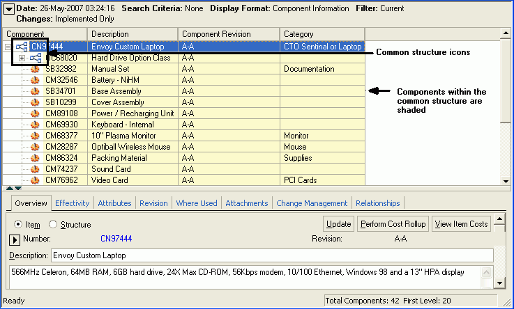
A window opens that displays all components in the structure. The common structure has an icon indicating that it is common and all of the components in the common structure are shaded.
Related Topics
See: Creating Structure Names, Oracle Product Information Management Implementation Guide
See: Viewing Structure Information
See: Defining Structures, Oracle Product Information Management Implementation Guide
Creating a Bill of Material , Oracle Bills of Material User's Guide
Referencing Common Bills and Routings, Oracle Bills of Material User's Guide
Viewing Structure Information
You can use the Product Workbench to view serial, date, revision, and unit effective structures as well as create and edit all but the serial effective structures.
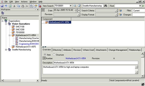
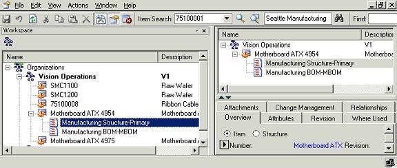
The structures that exist for an item are listed as children nodes under the item node in the favorites list and/or the item search results windows.
Structure list for an item
To open structures, you can do one of the following
-
Double click the structure node: Default values for explosion criterion are used to explode the structure. For unit and serial effective structures, user is required to provide unit number/serial number during this action.
-
Select structure node and right click Open action. Default values for explosion criterion are used to explode the structure. For unit and serial effective structures, user is required to provide unit number/serial number during this action.
-
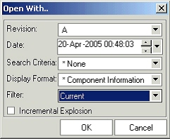
Select structure node and right click Open with action. A dialog is opened up with default values for the explosion criterion. User can change these values for exploding the structure against a different criterion.
Open With
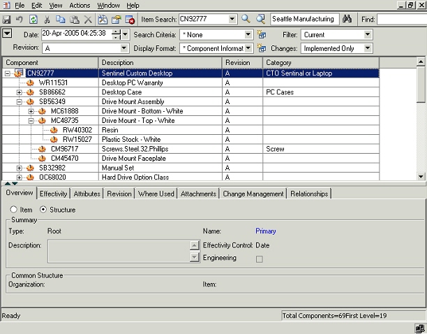
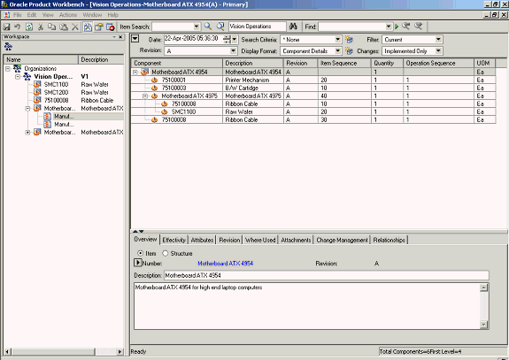
The structure is exploded according to the explosion criteria, and is displayed in a new window. This window provides a multi-level view of the exploded structure.
Exploded Structure
Change the selection in any of the following context switchers to change the information seen in the structure window as follows:
-
Revision:
This poplist lists all the revisions for the end item that have and have not been implemented. Based on the selection in this poplist, revision specific information changes appropriately. If the selected revision was an unimplemented revision, the value selected in the change order poplist will reflect the change order against the unimplemented item revision.
-
Date:
Specify the date on which the structure needs to be exploded. Based on the selected date, the selection in revision poplist also changes to the revision effective on the selected date.
-
Search Criteria: This poplist lists the criteria templates created by administrator as well as the user for the structure type. On selecting a criteria template, only those components that satisfy the criteria are listed in the structure. Intermediate nodes are listed even though they do not satisfy the criteria. This functionality is especially useful to filter only relevant components in a bill having a large number of components.
-
Display Formats: This poplist lists the display formats created by administrator as well as the user for the structure type. On selecting a value, the columns selected in the format are displayed for the structure. This reduces the clutter in the UI by displaying only that information that the user wants to view.
-
Filter: This drop list determines which rows to display based on the effective dating. Options include all dates, current and future dates, or the current date only.
-
Unit Number From:
This context switcher appears only in context of a unit effective structure and lists different unit numbers. User can choose a value to show only those components that are effective from the selected unit number.
-
Changes: This poplist contains the following values:
-
Current: This value is selected by default when a structure is exploded. On selecting this value, all the implemented components/information as on the explosion date are shown
-
Specific change order number: On selecting a pending change order, the structure is shown in the redline mode. The changes are shown highlighted as per the display scheme. e.g. a newly added component is shown in blue color. Based on the effectivity date of the selected change order, the selection in the item revision poplist changes appropriately.
-
Current and Pending: Selecting this value shows all the implemented information as well as pending changes. The pending changes could have been specified through multiple change orders. The pending changes are shown in redline mode.
-
Structure information is organized on different tabs in the ‘Details’ window:
Overview tab
Users need to select a subassembly node in the structure window to enable the structure radio button and then select the radio button. For the leaf nodes in a structure, the radio option is greyed out since they do not have a structure underneath them.
Basic structure header information like structure type, structure name, effectivity control, description and assembly type (engineering/manufacturing) is displayed. In case of a structure referencing another one, the organization and item fields in the common structure section are populated.
Users with edit privileges on the selected item can modify the structure description on this tab. Users can also navigate to html structure details pages by clicking the hyperlink against the structure name.
Overview tab
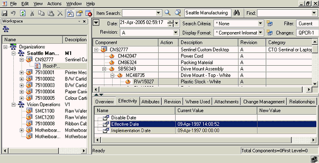
Effectivity tab
Effectivity information represents the rules that govern whether a component is active in the structure hierarchy.
The effectivity from and to information for the component (subassembly as well as leaf nodes) selected in structure window is shown on this TAB. The data type for effectivity information is dependent on the effectivity control for the structure as follows:
-
Date Effective Structure - Date.
-
Revision Effective Structure - Item revisions of component’s immediate parent.
-
Serial Effective Structure - Serial numbers of the end item
-
Unit Effective Structure - Unit numbers of the end item.
Effectivity tab
Attributes tab
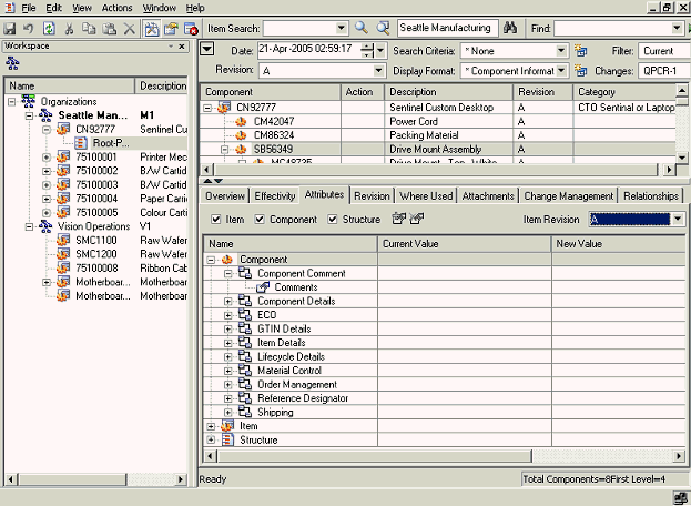
This tab shows the structure and component attributes (both seeded and user-defined) in a hierarchical view under the “structure” and “component” nodes respectively.
To view structure attributes, select a subassembly node in the structure and check the structure checkbox on the attribute tab. A new node “structure” will appear on the UI and user can expand the node to view different structure pages/attributes.
To view component attributes, select a component (subassembly or leaf level nodes) in the structure and check the component checkbox on the attribute tab. A new node “component” will appear on the UI and user can expand the node to view different component pages/attributes.
Attributes tab
Remaining tabs:
The following tabs function the same for items and structures. For a description of each tab, see: Viewing and Editing Item Information within Item Management.
-
Revision
-
Where Used
-
Attachments
-
Change Management
-
Relationship
Editing Structure Information
A structure contains information on the parent item, components, attachments, and descriptive elements.
Sometimes, similar changes need to be made to component attributes and item attributes for a large number of components in the structure. In the Product workbench, you can use the bulk edit feature to simultaneously effect similar changes to a large number of components in a structure.
Using Bulk Edit
-
Select an item from the Favorites list, and launch its bill.
Bulk Edit: Launch Bill
-
Modify any component or item attribute.
The structure is displayed in the mark up mode with the change highlighted.
In the example below, the quantity of component#75100008 (at level 1 in the structure) is changed from 1 to 99
Example of Component Modification
-
Select the component whose attribute value you have just changed, and launch the Bulk Edit Start action from the right click menu.
Bulk Edit - Start
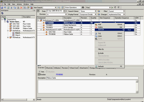
-
The structure is now displayed in the bulk edit mode.
Structure Display in Bulk Edit Mode
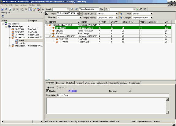
-
Select all other components for which this change in attribute value should be implemented.
Note: You can use the [SHIFT] and [CTRL] keys to select the components.
Bulk Edit - Component Selection
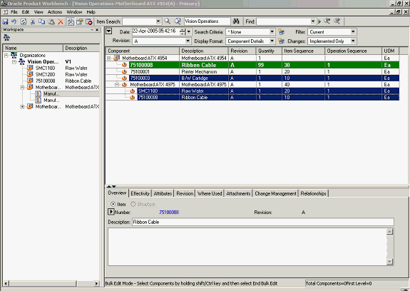
-
Launch Bulk Edit - Apply Changes action from the right click menu.
Bulk Edit - Apply Changes
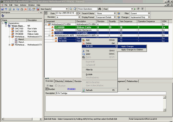
You can also select the Bulk Edit -- Apply Changes to Children action from the right click menu to change the attribute value of all children in a sub-assembly.
Thus, instead of independently selecting component ‘SMC1100’ & ‘75100008’ (which is available in the second level of the structure), you can select just the sub-assembly ‘Motherboard ATX 4975’ and launch the Bulk Edit -- Apply Changes to Children action. This would apply the attribute value changes to the sub-assembly ‘Motherboard ATX 4975’ as well as its children ‘SMC1100’ & ‘75100008’.
-
The structure is displayed in the mark up mode with the attribute values of all the selected components suitable modified.
Structure Display - Mark Up Mode
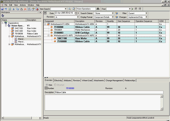
-
Save your work. The attribute value changes are implemented for all the selected components.
Note: If the structure type is under change control, then you need to create a change order to implement these changes.
Drag and Drop
Drag and drop features in product workbench greatly improve the efficiency during structure editing. User can select an item, then drag and drop it on a node in the structure window. Nodes from favorite items list, item search results and structure window can be dragged and dropped to the target structure. This will add a leaf level node or a subassembly based on the nature of the source item.
The following notes apply while executing drag and drop:
-
Drag and drop across organizations is not supported.
-
All component validation rules get honored during drag and drop
-
Drag and drop between different structure effectivities is not allowed
-
A multi-level structure copy gets executed when a user drags and drops a subassembly from one structure to another.
Deleting or Disabling Components
The procedure below describes how to delete/disable a component from a structure.
-
-
Select a node in the structure window.
-
Choose delete action from the right-click context menu or hit the delete key.
-
The delete node and components under it are all shown in the markup mode as per the configured color scheme.
-
Save the changes directly or on a change order based on the change policy.
Copy-Paste
The procedure below describes how to copy and paste nodes from one structure to another.
-
Select a node in structure window and perform a copy action from the right click menu. This copies the selection to the clipboard.
-
Select a node in the target structure and perform a paste action from the right click menu. This action adds the copied node to the target node in markup mode.
-
Save the changes directly or on a change order based on the change policy.
Note: Components/subassemblies gets added to the second structure without affecting the first structure. System behavior is same as in case of drag and drop.
Cut-Paste
The procedure below describes how to cut and paste nodes from one structure to another.
-
Select a node in structure window and perform a cut action using the right click option. This copies the selection to the clipboard
-
Select a node in the target structure and perform a paste action using the right click option. This action deletes the cut node from the source structure and adds it to the target structure. The changes in both the target as well as source structure are in markup mode.
-
Save the changes directly or on a change order based on the change policy.
In-place Editing or Excel like Editing
In-place editing of attributes is supported in product workbench. Users can double click on an attribute value and modify the same "in place". Based on the valueset attached to the attribute, the values that users can specify are restricted. On modification, the values are not directly saved; they are retained in the markup mode (as per the color scheme configured on per user basis) and users can save these changes directly or through a change order based on the change policies.
The following procedure describes how to perform in-place editing of attributes. The same procedure applies to item, component and structure attributes:
In-place Editing
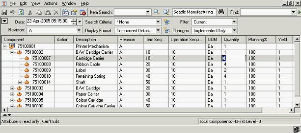
-
Double click on an attribute value displayed in the structure window. The field changes to edit mode based on the display type specified for the attribute. For example, a poplist is available to choose values from in case the display type for the attribute has been set as a poplist.
-
Provide a new value in place. Based on the valueset attached to the attribute, the values that can be specified get restricted.
Note: Certain attributes in the structure window cannot be edited. For e.g. component, description, UOM etc. Double clicking on these values will not open the UI in edit mode.
-
Save the changes directly or on a change order based on the change policy.
Using Defined Structure Names and Types
You can further classify alternate structures within a given structure type using structure names (previously known as “Alternate Designator”). Structure names allow you to create alternate design and manufacturing bills for a given item.
You can classify various structures in your business environments using Structure Types. Additionally Structure Types allow you to: Control effectivity of the components for a specific structure type, like date effectivity or revision effectivity etc,
User defined attribution – different types of structures and its components will have different attribution requirements, For Example, when performing analysis of various scenarios, every structure may need to capture the weight and cost attributes. Similarly components may need to capture attributes like “Mean Time between failure” which are unique to a component usage in a specific structure.
Attachment Categories – The types of documents required would change by the structure type. For eg. a Requirements structure will require a Marketing Analysis whereas Engineering structure may need a Drawing.
Viewing Structures in the Context of a Change Order
How to view structures in a change order
You can view a structure in markup mode for changes specified through a change order. You needs to select appropriate value in the “changes” context switcher in structure window. In the markup mode, these changes are shown highlighted (For example, the newly added components be shown in blue color, and deleted components be shown struckthrough in red color etc) and are very easy to visualize.
The procedure below describes how to view structure in context of change orders:
-
Open the structure using the procedure described in the view structure section.
-
Select a change order in the changes poplist available in the header section of the structure window to view the structure in markup mode. All the changes specified in the product information through the selected change order are shown highlighted as per the display scheme configured by the user.
Structure information in context of a change order
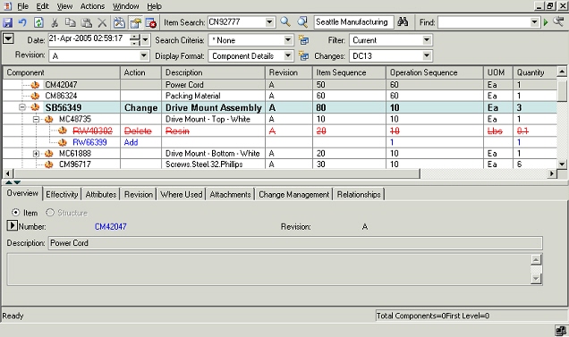
-
Optionally, specify more changes to the product information and click on save button. These new changes get saved in the change order in whose context the structure was being viewed.
Note: New changes get saved to the change order only if the user has edit privileges on the change order and the change order is in a state where changes are allowed.
How to create a new structure through a change order
Users with edit privileges on an item can create/edit structure for it. User is enforced to create/edit structure through a change order in case the change policy requires a Change Order for structure changes. User can also create/edit structure through a change order even for those items that do not require change order for structure changes. However, this step is optional and user is not enforced to create a change order in that scenario.
The procedure below describes how to create a new structure through a change order:
-
Create/edit a structure in markup mode as per the procedure outlined for the create structure flow.
-
Review the structure information and make necessary changes. Note that the structure information is available is displayed in the markup mode at this stage and is not yet saved.
-
Choose to create a change order from the menu (Actions->Create Change Order) to open the create change order dialog. Alternately, go to the change management TAB in the details section of the structure window and create new change order by clicking on appropriate icon.
Create Change Order
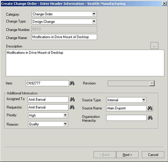
-
Choose a change order based category from the category poplist.
-
Choose a change order type from the change type poplist.
-
Specify the change order number, name and description in respective fields. In case of auto generated number, the number field is uneditable and the value is generated based on the auto numbering scheme specified for the selected change order type.
-
The item field gets defaulted to the parent item for which the structure is being created. User can choose a different item also. The revision field is also defaulted to the current item revision. Please note that item and item revision fields are editable based on the subject type specified for the selected change order type.
-
Based on the change order assignment rules specified for the selected change order type, the assigned to field is gets populated. User can change the assignee to a different person or a group.
-
The requestor field is defaulted to the person name from whose login the change order is being created. User can change the requestor to a different person on whose behalf the change order is being requested.
-
Specify a change priority and a reason. The values in the respective poplist are restricted as per the configuration carried out for the change order type.
-
Optionally, specify a source type and a source name.
-
In case of a global change order, specify the organization hierarchy where the change needs to be propagated.
Note: Based on the primary attributes configured for the change order type, certain attributes are shown in uneditable mode on the above dialog
-
Click on the next button to go to the attachment screen in the change order creation flow. User can create image markups and attach them to the change order besides other files. All attachments are stored in EBS repository only. Refer the attaching markups to issues/change order section for detailed procedure on creating and attaching markups.
Change Order Attachment List
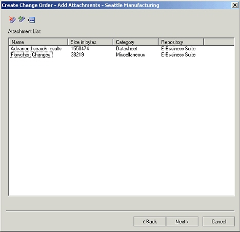
-
Click on the next button to go to the revised item screen in the change order creation flow.
Revised Items List
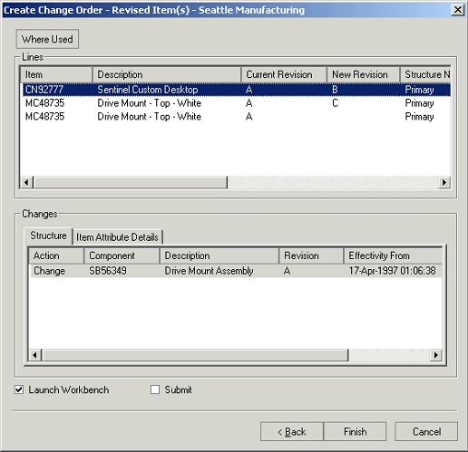
-
Review the changes captured on the change order (component changes as well as item attribute changes can be viewed in this release). All the changes specified in the markups should get captured.
-
Optionally, specify new revisions for the revised items. A user needs to double click on the new revision column to open the field in editable mode and then provide a new revision in-place.
-
Optionally, perform the where used query on the revised item and choose to add higher-level assemblies as revised items. Provide a new revision for these assemblies in the revised items list.
Revised Item Where Used
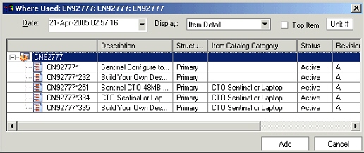
-
On the revised item list screen, check the submit checkbox to submit change order to workflow upon creation. Unchecking the checkbox will lead to creation of the change order in draft status.
-
Check the launch workbench checkbox to launch the change order details in html workbench upon successful creation.
-
Click on the Finish button to create the change order.
Marking Up Structures
Oracle Product Workbench provides a very intuitive and powerful user interface for authoring structure changes. Changes authored for structures are shown visually using industry standards for redlining and markup. You can author add, disable or modify any component attributes in a single interface. Redline/markup colors can be set based on your own preferences. You can save the changes to a structure inline or choose to process it through a formal change order. You can also review the redlines (changes) for a structures once a change order has been saved in the same interface. Additionally you can make further changes and add them to the same change order or to any existing pending change order.
How to configure markup colors
Oracle Product workbench enables each user to configure the markup colors as per their preferences. These settings are used to highlight modifications to the product information and help in improving the ease of visualization of changes.
Markup colors
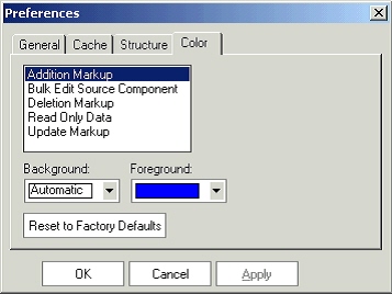
-
In the Product Workbench, invoke the Preferences dialog from the main menu (Edit->Preferences)
-
Navigate to the Color TAB.
-
Select the type of markup and specify a combination of background and foreground colors for the selected markup type. E.g. if the settings for Addition markup is an automatic background and a blue foreground, any new component addition to the structure will be shown in blue font color.
-
Click the Apply button.
-
To clear the user-settings and restore to the seeded color combination, click on the Reset to Factory Defaults button and hit on the apply button.
Attaching markups to change orders and issues
The procedure below describes how to create image markups and attach them to issues and change orders in Product Workbench:
-
On the create change order/issue flow, navigate to the attachment list screen.
-
Click on the image attachment icon and choose to load an image from the clipboard or from an existing file from the disk.
Image Attachments
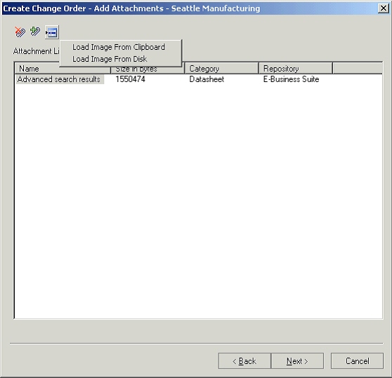
-
On the create markup screen, use the markup tools to draw lines with arrows or outline shapes, for example, to highlight areas in the image.
Markup Toolbar
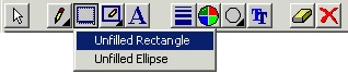
-
Use the text tool to create text labels to provide a description.
-
You can also pick items, drag them around, and modify line/font colors, font face, line weights, and fill etc.
Create Markup Screen
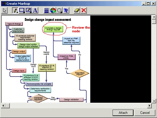
-
After the markup is completed, click on the attach button. Provide a name for the markup in the popup.
Create Markup as
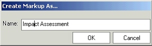
-
Choose the OK button, and provide the attachment category and description on the attachment details dialog. Note that only EBS repository is supported in the current release of Product Workbench.
Attachment details
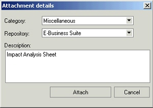
-
Choose the Attach button. The markup is listed on change order/issue attachment screen at the end of this step.
Creating New Issues or Change Orders
How to create a new issue or change order in the Product Workbench
The procedure below describes how to create a new issue or change order in the Product Workbench:
-
Choose to create an issue from the menu (Actions->Create Issue) to open the create issue dialog. Alternately, go to the change management TAB in the details section of the structure window and create new issue by clicking on appropriate icon.
Important: The process used to create a new change order using the Product Workbench is similar to that of creating a new issue. Any differences will be noted.
Create Issue
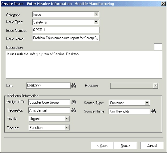
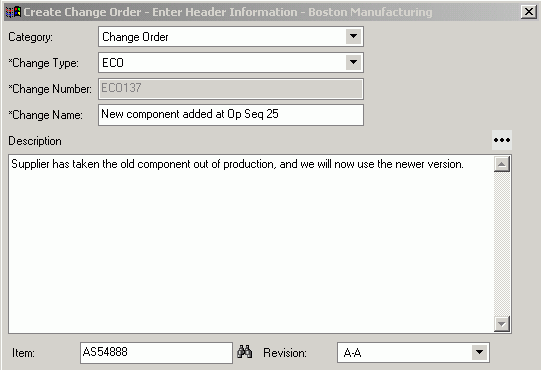
-
Choose an issue or change order based category from the category poplist.
-
Choose an issue type or change order type from the change type poplist.
-
Specify the issue or change order number, name and description in respective fields. In case of auto generated number, the number field is uneditable and the value is generated based on the auto numbering scheme specified for the selected issue or change order type.
-
The item field gets defaulted to the selected item. User can choose a different item also. The revision field is also defaulted to the current item revision. Please note that item and item revision fields are editable based on the subject type specified for the selected issue or change order type.
-
Based on the issue or change order assignment rules specified for the selected issue or change order type, the assigned to field is gets populated. Users can change the assignee to a different person or a group.
-
The requestor field is defaulted to the person name from whose login the issue is being created. User can change the requestor to a different person on whose behalf the issue is being requested.
-
Specify a change priority and a reason. The values in the respective poplist are restricted as per the configuration carried out for the issue type.
-
Optionally, specify a source type and a source name.
-
Choose the Next button to go to the attachment screen in the issue creation flow. User can create image markups and attach them to the issue besides other files. All attachments are reposted in EBS repository only. Please refer to the attaching markups to issues/change order section for detailed procedure on creating and attaching markups.
Issue Attachment List
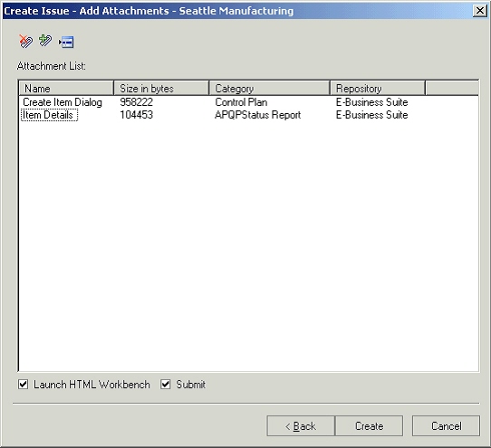
Structure Change Management in Product Workbench
Users can author changes to components such as adding or disabling or modifying components and their effectivity to a specific end item and its revision or its immediate parent in a revision-effective structure. Users can specify the effectivity of these component changes in terms of the 'Effective From Revision' and 'Effective To Revision' of the parent item. These changes can be implemented using a change order.
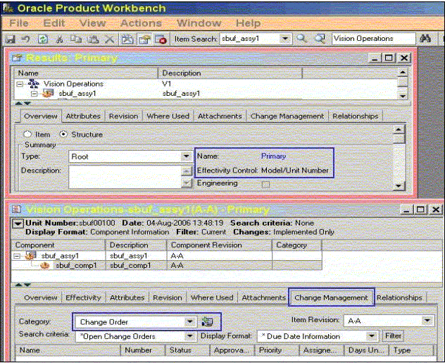
Valid Component Types
The system enables you to add valid component user items to a structure. It also enables you to copy a structure to a new structure when the item list of values includes only valid items that have defined component types for the parent item type.
Adding Components to a Structure
When adding components to a structure using the ‘Add’ right click action, the Item Search and Item Advanced Search restricts the list of component items that can be added as components to an item. This list will include only the valid component user items configured for the item type of the parent/subassembly.
When adding components to a structure by dragging and dropping components from Favorites, Item Search Results, the system restricts the list of component items that can be added as components to an item. The component items, which can be dragged and dropped, include only the valid component user items configured for the item type of the parent/subassembly.
Structure Copy
When copying a structure to a new structure, the Item list of values (LOV) for the target structure includes only the valid items that have defined component types for the parent item type. Therefore, when you are defining the valid component item types for parent item types, if the parent item type is also a valid component item type, define it as a component item type, as well. Complete the same validation when copying a structure for a subassembly , which is added by dragging from another structure window.
Structure Bulkload and Open Interface
When importing a structure through bulkload or the open interface, the system automatically considers item type validations.
Functional Rules for Structure Bulkload and Open Interfaces
-
Define User Item Types in the Item Master
-
Define Valid Component Item Types for a Parent User Item Type
-
Validate a parent item type with multiple component types in an OR condition
-
Item LOV’s in Add Component and Item Advanced Search will validate the valid component item types for a parent item type to which the component is being added
-
Target Structure Item LOV will validate the valid component item types for a parent item type
-
Structures created through bulkload or Open interface need to validate the valid component item types
-
Once structures have been defined with existing valid component types on deletion of a component user item type for a parent item type, all new structures will honor the new component user item types definition.