Initial Configuration
This chapter covers the following topics:
- Creating the Engine Domain
- Creating the User Interface Domain
- Starting the Engine Admin Server
- Starting the User Interface Admin Server
- Configuring the JDBC Data Source for the Engine Domain
- Configuring the JDBC Data Source for the User Interface Domain
- Deploying the Rapid Planning Administration Application in the User Interface Domain
- Setting the Initial Configuration for the Rapid Planning User Interface and Engine
- Creating the Managed Servers
- Deploying and Starting the Engine Application
- Deploying and Starting the User Interface Application
Creating the Engine Domain
Perform the procedure below to create the Engine Domain.
-
Go to <WLS_HOME>/common/bin folder.
Example:
cd <installation_path..>/wlserver_10.3/common/bin
-
Run config.sh.
Example:
/config.sh

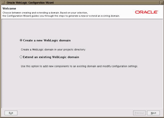
The Oracle WebLogic Configuration Wizard appears.
-
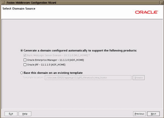
Select Create a new WebLogic domain, and click Next. The Select Domain Source screen appears.
-
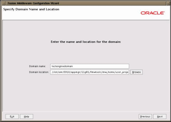
Select Generate a domain configured automatically to support the following products. Do not select any check box options. Keep the default settings. Click Next. The Specify Domain Name and Location screen appears.
-
Provide the Domain name and Domain location, and click Next. The domain location should be <WLS_HOME>/user_projects/domains. The Configure Administrator User Name and Password screen appears.
-
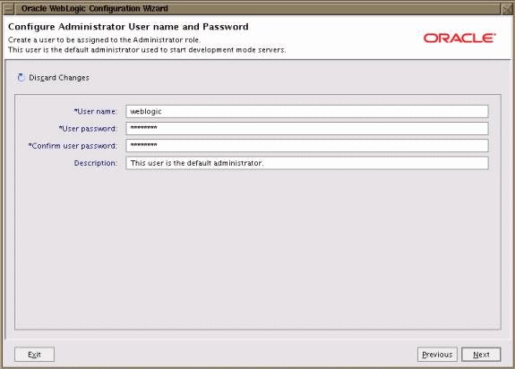
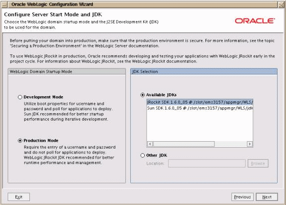
Enter the User name, User password and Conform user password of your choice, and then click Next. The password must be alphanumeric. The Configure Server Start Mode and JDK screen appears.
-
Perform the following:
-
Select Production Mode.
-
In JDK Selection region, select JRockit SDK 1.6 0_05.
-
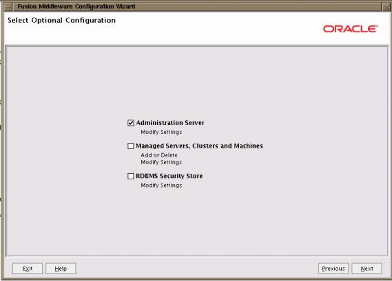
Click Next. The Select Optional Configuration screen appears.
-
-
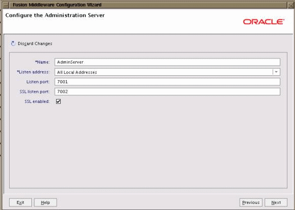
Select the Administration Server option only and click Next. The Configure the Administration Server screen appears.
-
Enter the following details and click Next:
-
Name - Enter the name of the Admin Server.
-
Listen Address - The Admin Server listen port address.
-
Listen Port - Enter the server listen port. Check the availability of the port number before entering a value.
-
SSL listen port - Enter the SSL Listen Port. Check the availability of the port number before entering a value.
-
Check the SSL enabled option.
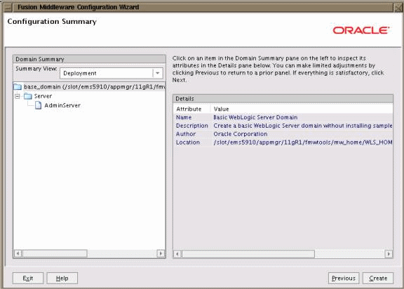
The Configuration Summary screen appears.
-
-
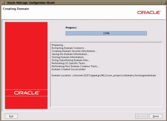
Review the details. If you want to modify any settings, use the Previous button to return to the appropriate screen. If no changes are required, click Create. The Creating Domain screen appears to display the system progress.
-
When the domain is complete, click Done.
-
Go the Engine Domain directory:
Example:
$ cd /slot/ems3424/appmgr/WLS/user_projects/domains/wls_app3424/
In the example above, wls_app3424 is the engine domain directory.
-
Create output/ and log/ directories as follows:
-
$ mkdir -m 777 output/
-
$ mkdir -m 777 log/
-
Creating the User Interface Domain
Perform the following procedure to create a new User Interface (UI) Domain.
-
Go to <WLS_HOME>/common/bin.
Example:
cd /slot/ems3157/appmgr/<WLS_HOME>/common/bin
-
Run config.sh.
Example:
/config.sh
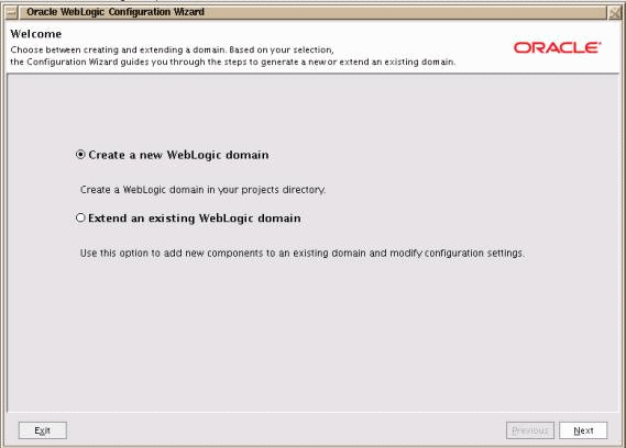
The Oracle WebLogic Configuration Wizard appears.
-
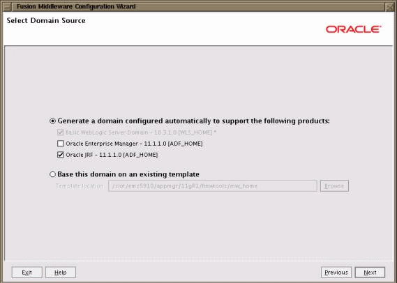
Select Create a new WebLogic Domain, and click Next. The Select Domain Source screen appears.
-
Select Generate a domain configured to support the following products, select the Oracle JRF option, and click Next. The Specify Domain and Location screen appears.
-
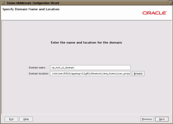
Provide the Domain name and Domain location, and click Next. The Domain location should be <WLS_HOME>/user_projects/domains. The Configure Administrator User Name and Password screen appears.
-
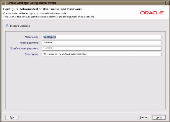
Enter the User name, User password and Conform user password of your choice, and then click Next. The Configure Server Start Mode and JDK screen appears.
-
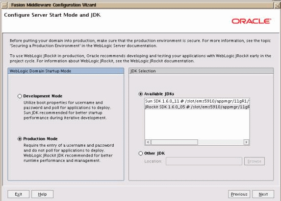
Perform the following:
-
Select Production Mode.
-
In JDK Selection region, select JRockit SDK 1.6 0_05 option.
-
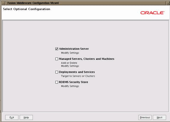
Click Next. The Select Optional Configuration screen appears.
-
-
Select the Administration Server option only and click Next. The Configure the Administration Server screen appears.
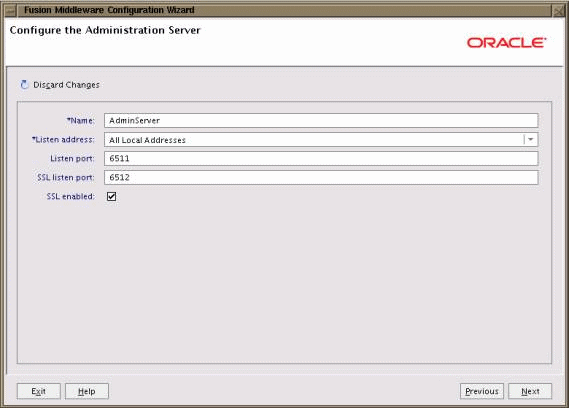
-
Enter the following details and click Next:
-
Name - Enter the name of the Admin Server
-
Listen Address - Enter the listen address.
-
Listen Port - Enter the server listen port. Check the availability of the port number before entering a value.
This Listen Port is used to set up the profile MSC_RP_HOST_URL as mentioned in the Performing Pre-Configuration Setup section.
-
SSL listen port - Enter the SSL Listen Port. Check the availability of the port number before entering a value.
-
SSL enabled - Select the SSL enabled option.
The Configuration Summary screen appears.
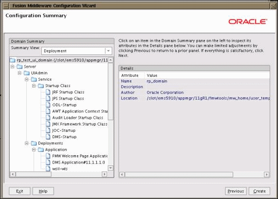
-
-
Review the details. If you want to modify any settings, use the Previous button to return to the appropriate screen. If no changes are required, click Create. The Creating Domain screen appears to display the system progress.
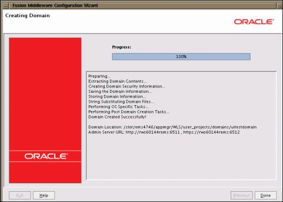
-
When the domain is complete, click Done.
-
The Rapid Planning application uses graphical features. In order to enable theses features, the following steps need to be executed:
-
Edit the file setDomainEnv.sh available inside domain home bin directory.
-
Add the following to the property:
-Djava.awt.headless=true to EXTRA_JAVA_PROPERTIES
-
Starting the Engine Admin Server
Perform the following procedure to start the Engine Admin Server.
-
Under <WLS_HOME>, go to the directory user_projects/domains/<ENGINEDOMAINNAME>/
Example:
/slot/ems3157/appmgr/user_projects/domains/testenginedomain
-
Run the script startWeblogic.sh to start the Admin Server.

-
The console requests the username and password. Enter the Engine Domain credentials.

The console displays “Server started in RUNNING mode”.

-
Open a web browser and type in the URL/address in the format below:
http://<$Machine_Name>:$Port_No/console
Example:
http://rws60144rems:7901/console
where $MACHINE_NAME is the host name of the machine on which the WebLogic Server is running (for example, rws60144rems.us.oracle.com) and $Port_No is the Admin Server Listen port number specified when the Engine domain was created.

The WebLogic Server Administration Console appears.
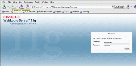
-
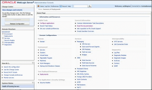
Enter the Admin Server Username and Password, and click Log In. The WebLogic Administration Console home page appears.
Starting the User Interface Admin Server
Perform the following procedure to start the User Interface (UI) Admin Server.
-
Under <WLS_HOME>, go to the directory user_projects/domains/<UIDOMAINNAME>/.
Example:
/slot/ems4746/appmgr/user_projects/domains/testuidomain
-
Run the script startWeblogic.sh to start the Admin Server.

-
The console requests the username and password. Enter the User Interface Domain credentials.

The console displays “Server started in RUNNING mode”.

-
Open a web browser and type in the URL/address in the in the following format:
http://<Machine_Name>:<Port_No>/console
Example:
http://rws60144rems:6501/console
where $MACHINE_NAME is the host name of the machine on which the WebLogic Server is running (for example, rws60144rems.us.oracle.com) and $PORT_NO is the Admin Server Listen port number specified when the User Interface Domain was created.

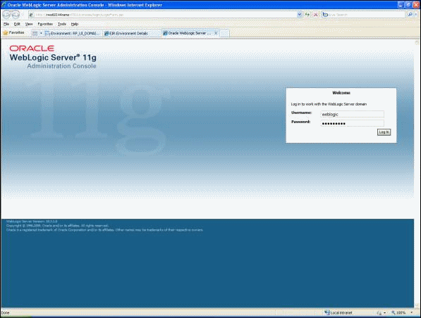
The WebLogic Server Administration Console appears.
-
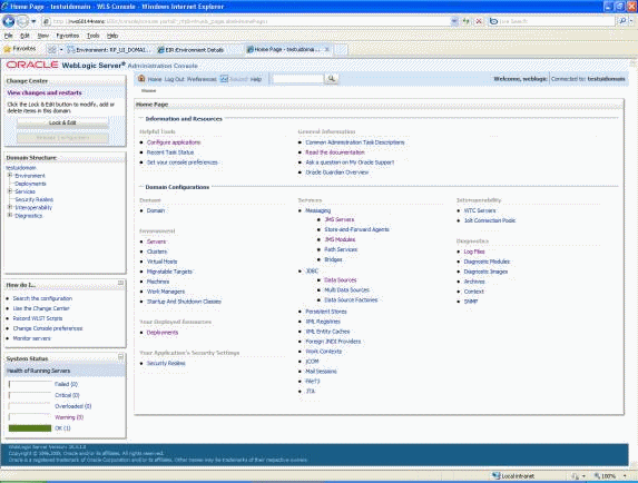
Enter the User Interface Admin Server Username and Password, and click Log In.
-
Return to the UNIX console, and go to the User Interface Domain home (the path where UI domain is installed).
-
Create a new directory 'mds' in the following location:
<UI_Domain_Home>/servers/<Admin_Server>/mds
Example:
<installation_path>/user_projects/domains/uitestdomain/servers/AdminServer/mds
-
To create a file persistence store on the WebLogic Server, perform the following:
-
Click Lock & Edit from the Change Center region in top left corner to change the domain configuration.
-
Click the Persistent Stores link (or you can navigate to Services > Persistent Stores from the Domain Structure region).
-
Click New.
-
Select Create File Store.
-
Enter Name as 'mds-repos'.
-
Select AdminServer from the Target list.
-
Set the path to <UI_Domain_Home>/servers/<Admin_Server>/mds.
-
Click OK.
-
From Change Center, click Activate Changes.
-
Configuring the JDBC Data Source for the Engine Domain
Verify the Engine Domain Admin Server is up and running before performing this procedure.
-
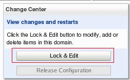
Click Lock & Edit from the Change Center region in top left corner to change the domain configuration.
-
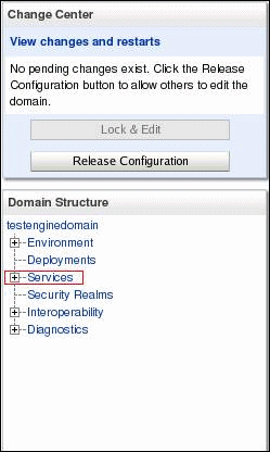
From the Domain Structure region, expand the Services tree node.
-
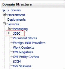
From Services tree, expand the JDBC tree node.
-
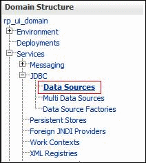
Select Data Sources.
-
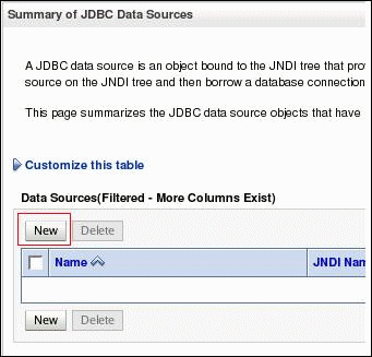
Click New.
-
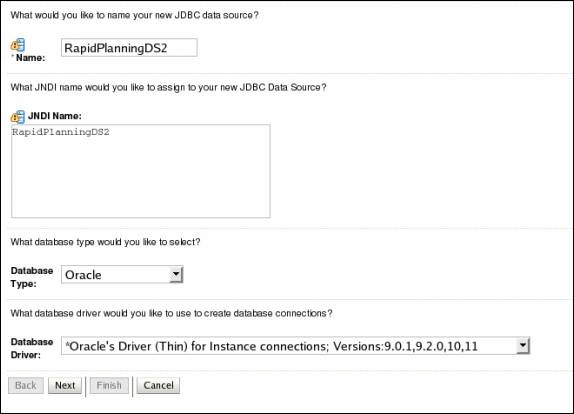
Enter the information as shown below, and click Next.
-
Name - Enter 'RapidPlanningDS2'.
-
JNDI Name - Enter 'RapidPlanningDS2'.
-
Database Type - Select Oracle.
-
Database Driver - Select Oracle's Driver (Thin) for instance connections: 9.0.1, 9.2.0, 10, 11.
Enter Name and JNDI Name as 'RapidPlanningDS2'. Check Troubleshooting for JDBC Driver specific issues.
-
-
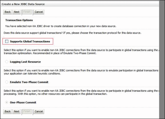
Deselect Supports Global Transaction, and click Next.
-
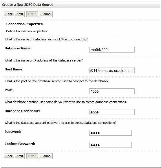
Enter the information as shown below and click Next.
-
Database Name - Enter database name (example, ma0dv220).
-
Host Name - Enter host name (example, rws60147rems.us.oracle.com ).
-
Port - Enter port number (example, 1555).
-
Database User Name - Enter database user name.
-
Password - Enter database user name password.
-
-
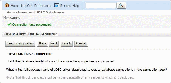
Select Test Configuration.
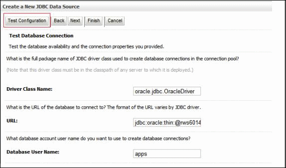
If JDBC is set up correctly, then a message "Connection test succeeded" appears.
-
Click Next.
-
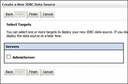
Do not select any target server. Click Finish.
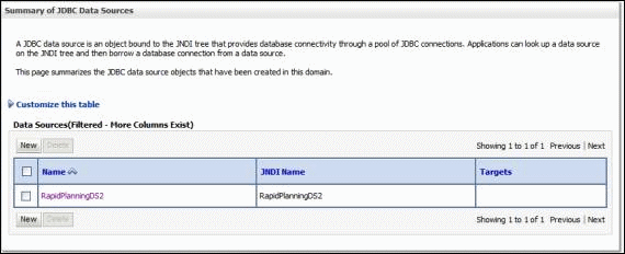
The Summary of JDBC Data Source page appears. The data source appears on the page.
-
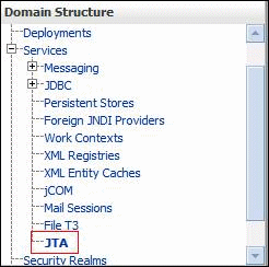
In the Domain Structure region, select Services > JTA. Select the Configuration tab and then the JTA tab.
-
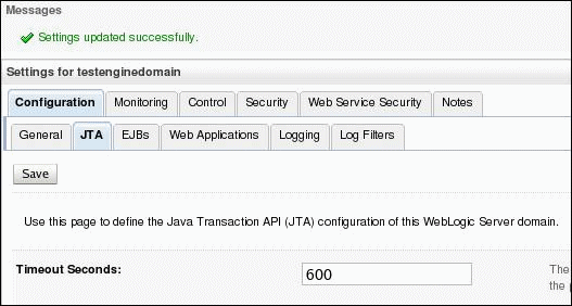
Set Timeout Seconds to '600' seconds as shown below, and click Save.
-
From Change Center, click Activate Changes.

Once Activation is complete, the message "All changes have been activated. No restarts are necessary." appears.

The JDBC Resource has been successfully set up.
Configuring the JDBC Data Source for the User Interface Domain
Verify the User Interface (UI) Domain Admin Server is up and running before performing this procedure.
-
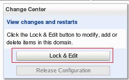
Click Lock & Edit from the Change Center region in top left corner to change the domain configuration.
-
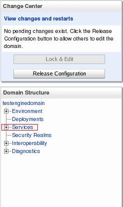
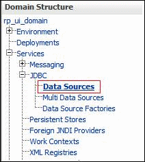
From the Domain Structure region, expand the Services tree node
-
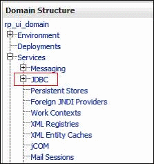
From the Services tree, expand the JDBC node.
-
From JDBC tree, select Data Sources.
-
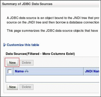
Click New.
-
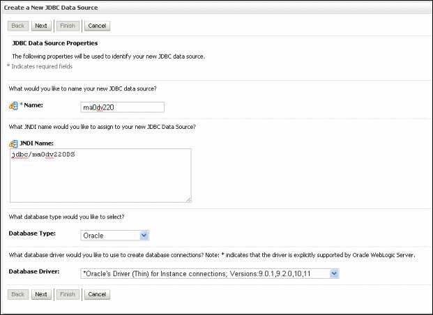
From the Create a New JDBC Data Source page, enter the following information as shown below, and click Next.
-
Name - Enter 'ma0dv220'.
-
JNDI Name - Enter 'jdbc/ma0dv220DS'.
-
Database Type - Select Oracle.
-
Database Driver - Select Oracle's Driver (Thin) versions: 9.0.1, 9.2.0, 10, 11.
-
-
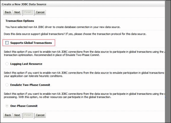
Deselect Supports Global Transaction, and click Next.
-
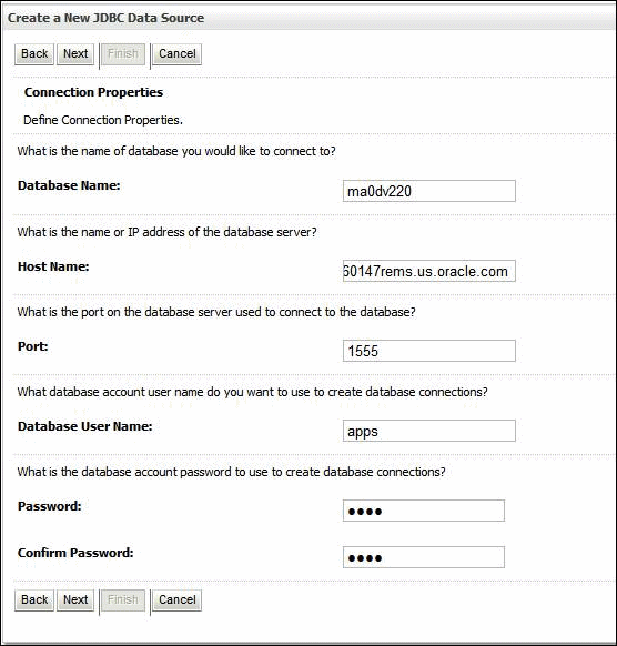
Enter the following information, and click Next.
-
Database Name - Enter database name (example, ma0dv220).
-
Host Name - Enter host name (example, rws60147rems.us.oracle.com).
-
Port - Enter port number (example, 1555).
-
Database User Name - Enter database user name.
-
Password - Enter database user name password.
-
-
Select Test Configuration.
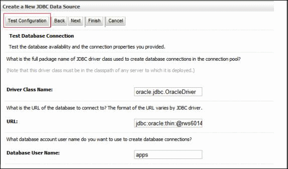
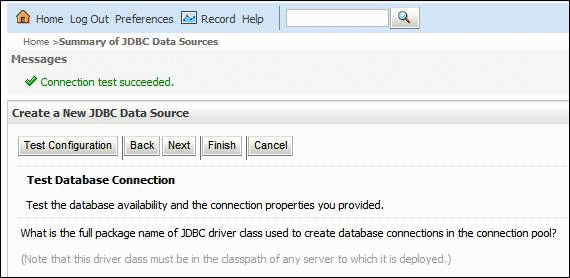
If JDBC is set up correctly, then a message "Connection test succeeded" appears.
-
Click Next.
-
Select the default Admin Server as the target (as shown in the example below), and click Finish.
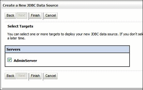
The Summary of JDBC Data Source page appears. The data source appears on the page.

-
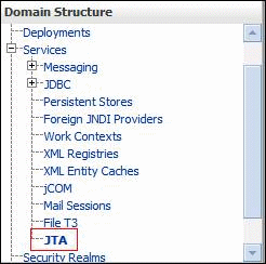
From the Domain Structure region, select Services > JTA. Select the Configuration tab and then the JTA tab.
-
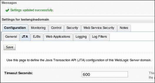
Set Timeout Seconds to '600' seconds as shown below, and click Save.
-
From the Change Center, click Activate Changes.

Once activation is complete, the message "All changes have been activated. No restarts are necessary." appears.

The JDBC Resource has been successfully set up.
Deploying the Rapid Planning Administration Application in the User Interface Domain
Perform the following procedure to deploy the Rapid Planning Administration application in the User Interface (UI) Domain.
Verify the UI Domain Admin Server is up and running before performing this procedure.
-
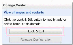
Click Lock & Edit from the Change Center region in top left corner to change the domain configuration.
-
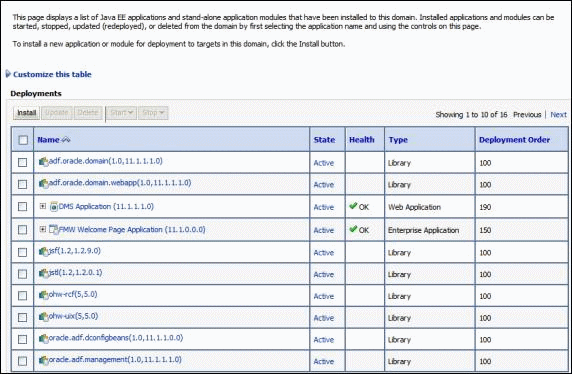
From Domain Structure region, select Deployments.

The Java EE applications appear on the page.
-
Click Install.
-
Navigate to the path where the EAR file is located, and select the ORPAdmin.ear file. The EAR file is in the ORPTEMP location, as mentioned in Performing Pre-Configuration Setup section of this document.

-
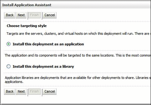
Select Install this deployment as an application, and click Next.
-
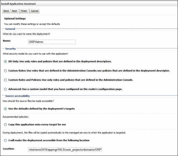
Select the options you require, and click Next.
-
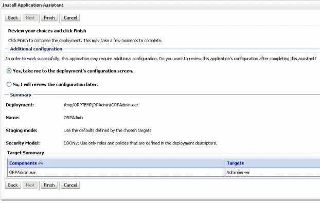
Click Finish, and then click Save (if applicable).
-
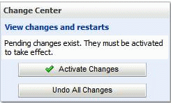
Select Activate Changes.
The deployment appears in the table.
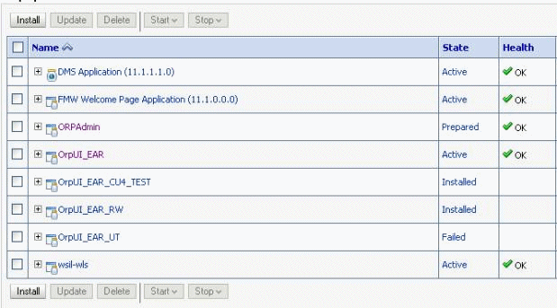
Optionally, you can restart the AdminServer after deployment.
-
Select ORPAdmin. Click Start > Servicing all requests. Click Next. The Start Application Assistant page appears. Click Yes.
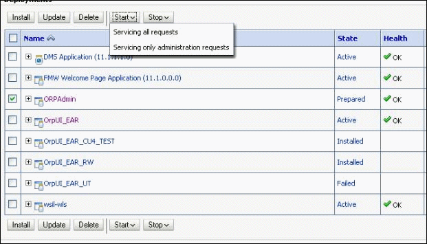
A message appears to inform you that the start requests have been sent to the selected deployments.

-
Log on to the application using following link format in your web browser:
Example:
http://<MACHINE_NAME>:<PORT_NO>/rpadmin/faces/oracle/apps/msc/orp/admin/ui/page/AdminMainUI.jspx
Example:
http://rws60144rems:6501/rpadmin/faces/oracle/apps/msc/orp/admin/ui/page/AdminMainUI.jspx
The EBS home page appears.
-
Select Advanced Planning Administrator responsibility, and then select Rapid Planning (Setup and Configuration).
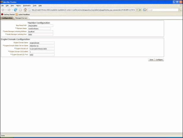
Setting the Initial Configuration for the Rapid Planning User Interface and Engine
Verify the Engine Domain Admin Server is up and running before performing this procedure.
-
On Rapid Planning Admin User Interface (UI) home page, click the Configuration tab.
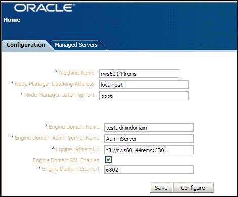
-
Enter the following information.
Machine Details
-
Machine Name - Host name of the machine on which the WebLogic Server is running (example, rws60144rems.us.oracle.com).
-
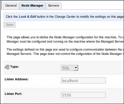
Node Manager Listen Address - Set to localhost.
-
Node Manager Listen Port - Set to 5556.
Engine Domain Details
-
Engine Domain Name - Enter the name of Engine Domain provided during installation in Creating the Engine Domain.
-
Engine Domain Admin Server Name - Enter the name of Engine Domain Admin Server provided during installation in Creating the Engine Domain.
-
Engine Domain Url - Enter t3://<Machine_Name>:<Port_No>. Use protocol t3 and not http.
-
Engine Domain SSL Enabled - Select this option.
-
Engine Domain SSL Port - Enter the SSL Port Number provided during installation in Creating the Engine Domain.
-
-
Once you have entered all the values, click Save.
-
Verify the information entered, and click Configure. The WebLogic Credentials dialog appears.
-
Enter the user credentials for Engine Domain Admin Server, and click OK.

After configuration, the machine and Node Manager are set up.
-
Verify the machine and Node Manager setup.
-
Log in to WebLogic Administration Console from your browser.
-
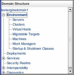
From the Domain Structure region, expand the Environment node.
-
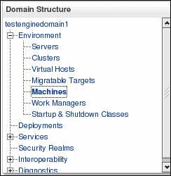
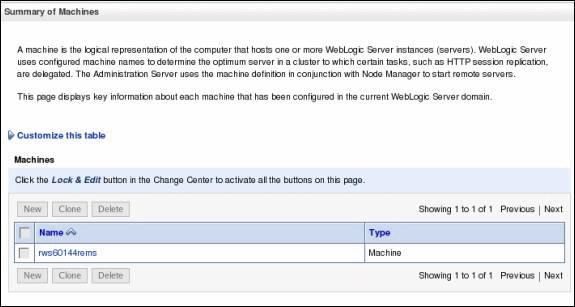
Select Machines. The newly created machine appears on the Summary of Machines page.
-
Select a machine name to view the machine details.
-
The settings for the server appear, as shown below.

-
Select the Node Manager tab to view Node Manager details.
-
Creating the Managed Servers
Perform the following procedure to create the necessary Managed Servers.
Verify the Engine Domain Admin Server is up and running before performing this procedure.
-
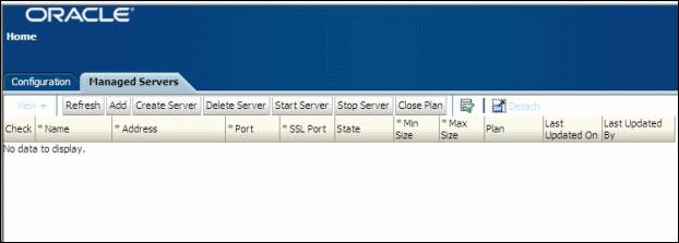
In Rapid Planning Admin User Interface (UI), select the Managed Servers tab.

-
Cick the Add. An empty row appears.
-
Enter the following information in the new row:
-
Name - Enter the name of the Managed Server.
-
Address - Enter the Listen Address for Manager Server
-
Port - Enter the Listen Port for Manager Server.
-
SSL Enabled - Select the Check box to enter SSL Port Number.
-
SSL Port - Enter the Secured Socket Listen Port for Managed Server.
-
Min Size - Enter the minimum heap size memory argument for Manager Server.
-
Max Size - Enter the maximum heap size memory argument for Manager Server.

-
-
Repeat the steps above to add and define all the necessary Managed Servers. Make sure the Managed Server names are unique.
-
After the information is entered for all the servers, select the Check box for the servers that you want to create.
-
Click Create Server. You are prompted for username and password.
-
Enter the user credentials for Engine Domain Admin Server, and click OK.
Wait for return of control. Once control is back; click Refresh. Verify that all the created servers are in the "Running" state.

-
If the server has not started, select the server and click Start Server.
Deploying and Starting the Engine Application
Verify the Engine Domain Admin Server is up and running before performing this procedure.
To start Engine Domain Server, refer to the Starting the Engine Admin Server.
-
Click Lock & Edit from the Change Center region in top left corner to modify the domain configuration.
-
From Domain Structure region, click Deployments. The Deployments screen appears.
-
Click Install.

-
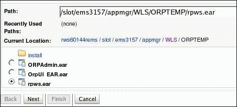
Navigate to the path where the EAR file is located, and select the rpws.ear file. The EAR file is located in the ORPTEMP location as mentioned in Performing Pre-Configuration Setup section of this document.
-
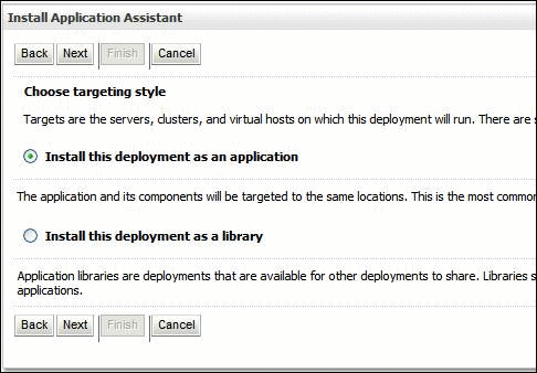
Select Install this deployment as an application, and click Next.
-
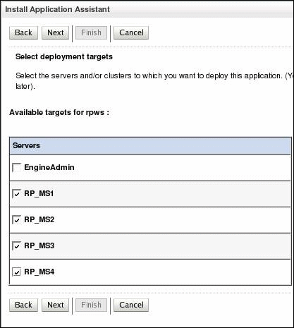
Select all the Managed Servers as the targets for the application, and click Next. Do not select the Admin Server. The Optional Settings page appears.
-
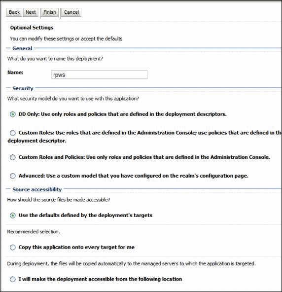
On the Optional Settings page, keep the default settings, and click Next.
-
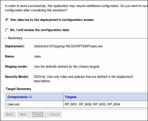
Click Finish, then click Save.
-
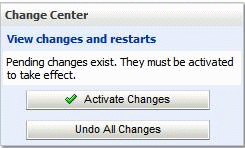
Click Activate Changes.
Use the Deployments page to control or modify deployments.

-
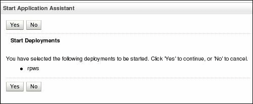
Select the check box for rpws. Click Start > Servicing all requests. Click Next. The Start Application Assistant page appears.
-
Click Yes.
A message appears to inform you that the start requests have been sent to the selected deployments.

Deploying and Starting the User Interface Application
Perform the following procedure to deploy and start the User Interface (UI) application.
Verify the UI Domain Admin Server is running before performing this procedure.
To start UI Domain Server, refer to Starting the Engine Admin Server. Provide the UI Domain credentials (machinename, Port_No, username and password) to start the server .
-
Click Lock & Edit from the Change Center region in top left corner to change the domain configuration.
-
From Domain Structure region, click Deployments. The Deployments page appears.
-
Click Install.

-
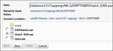
Navigate to the path where the EAR file is located. The EAR file is in the ORPTEMP location as mentioned in Performing Pre-Configuration Setup section of this document. Select the OrpUI_EAR.ear file. Click Next.
-
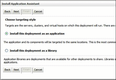
Select Install this deployment as an application, and click Next. The Install Application Assistant page appears.
-
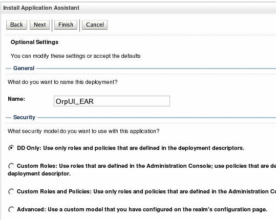
Keep the default settings and click Next. The Review Your Choices page appears.
-
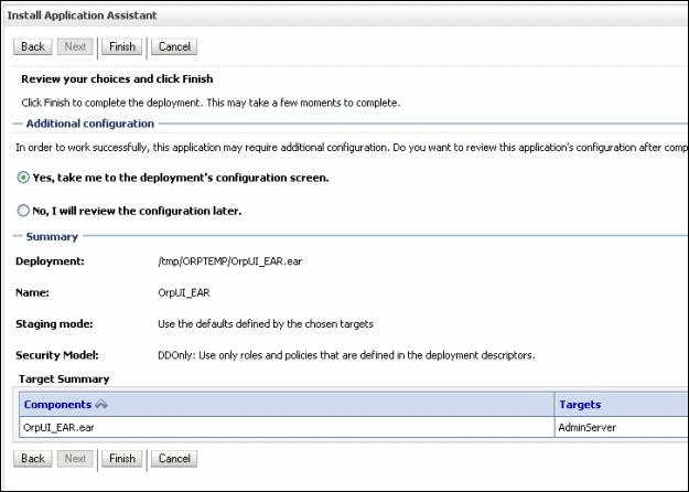
Click Finish, and then click Save.
-
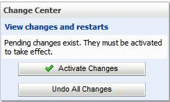
Click Activate Changes.
-
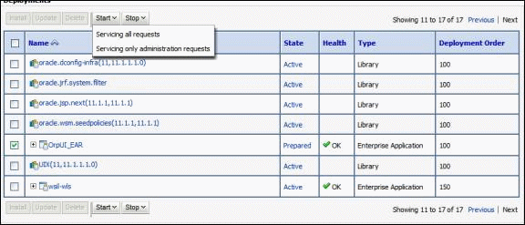
Select the check box for OrpUI_EAR. Select Start > Servicing all requests. Click Next. The Start Application Assistant page appears.
-
Click Yes.
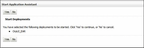
A message appears to inform you that start requests have been sent to the selected deployments.

-
Log in to the application using following link format in your web browser:
Example Format:
http://<Machine_Name>.us.oracle.com:<Port_No>/rapidplanning/faces/RPMainUI
Example:
http://rws60144rems.us.oracle.com:7001/rapidplanning/faces/RPMainUI
The Oracle Applications Login page appears.
-
Enter the Username and Password, and click OK.
-
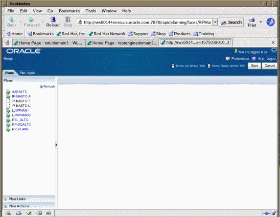
Once home page appears, select Oracle Supply Chain Simulation Planner > Plans, Inputs and Simulations. The Plans page appears.
-
From the Plans region, select a plan to start working on it. The plan details page appears.
