| C H A P T E R 3 |
|
Diagnostics Tools |
This chapter contains information about diagnostic tools that you can use to determine the status of the Sun Blade X6220 server module and components.
This chapter contains the following topics:
The following component information is available through the service processor (SP) Integrated Lights Out Manager (ILOM).
See the Integrated Lights Out Manager (ILOM) Administration Guide for ILOM 1.1.1, 820-0280, for more information.
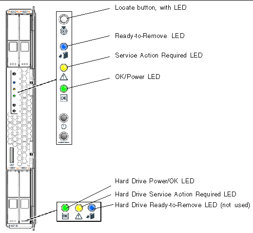
The Sun Blade X6220 server module has external and internal system status LEDs.
FIGURE 3-1 shows the locations of the external status indicator LEDs.

Refer to TABLE 3-1 for descriptions of the LED behavior.
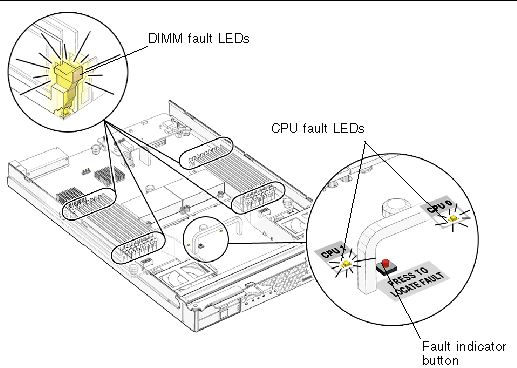
These servers have internal status indicator LEDs for the DIMM slots and the CPUs.
When the board is removed from the chassis, you can press a fault indicator button to view the location of the DIMM or CPU that has failed.

See TABLE 3-2 for internal LED behavior.
The system BIOS provides a rudimentary power-on self-test (POST). The basic devices required for the server to operate are checked, memory is tested, the LSI 1068 disk controller and attached disks are probed and enumerated, and the two dual-gigabit Ethernet controllers are initialized.
The progress of the self-test is indicated by a series of POST codes. Refer to Appendix B for information on BIOS POST codes.
These codes are displayed at the bottom right corner of the system's VGA screen (once the self-test has progressed far enough to initialize the video monitor). However, the codes are displayed as the self-test runs, and they scroll off the screen too quickly to be read. An alternate method of displaying the POST codes is to redirect the output of the console to a serial port (see Section 3.3.2, Redirecting Console Output).
The message BMC Responding is displayed at the end of the POST.
The BIOS POST memory testing is performed as follows:
1. The first megabyte of DRAM is tested by the BIOS before the BIOS code is shadowed (that is, copied from ROM to DRAM).
2. Once executing out of DRAM, the BIOS performs a simple memory test
(a write/read of every location with the pattern 55aa55aa).
|
Note - This memory test is performed only if Quick Boot is not enabled from the Boot Settings Configuration screen. Enabling Quick Boot causes the BIOS to skip the memory test. See Section 3.3.3, Changing POST Options for more information. |
3. The BIOS polls the memory controllers for both correctable and uncorrectable memory errors and logs those errors into the service processor.
Use these instructions to access the service processor and redirect the console output so that the BIOS POST codes can be read.
1. Connect a dongle cable to the server module universal connector port (UCP). See FIGURE 1-2.
2. Connect a monitor to the dongle cable video port and a keyboard to a USB port.
3. Power cycle or power on the server.
4. Initialize the BIOS setup utility by pressing the F2 key while the system is performing the power-on self-test (POST).
5. When the BIOS Main Menu screen is displayed, select Advanced.
6. When the Advanced Settings screen is displayed, select IPMI 2.0 Configuration.
7. When the IPMI 2.0 Configuration screen is displayed, select the LAN Configuration menu item.
8. Select the IP Address menu item.
The service processor's IP address is displayed in the following format:
Current IP address in BMC: xxx.xxx.xxx.xxx
9. Start a web browser and type the service processor's IP address in the browser's URL field.
10. When you are prompted, type a user name and password as follows:
User name: root
Password: changeme
11. When the ILOM Service Processor GUI screen is displayed, click the Remote Control tab.
12. Click the Redirection tab.
13. Set the color depth for the redirection console at either 6 or 8 bits.
14. Click the Start Redirection button.
The remote console window appears and prompts you for your user name and password again.
15. When you are prompted, type a user name and password as follows:
User name: root
Password: changeme
The current POST screen is displayed.
These instructions are optional, but you can use them to change the operations that the server performs during POST.
1. Connect a dongle cable to the server module universal connector port (UCP). See FIGURE 1-2.
2. Connect a monitor to the dongle cable video port and a keyboard to a USB port.
3. Initialize the BIOS setup utility by pressing the F2 key while the system is performing the power-on self-test (POST).
4. When the BIOS Main Menu screen is displayed, select the Boot menu.
5. From the Boot Settings screen, select Boot Settings Configuration.
6. On the Boot Settings Configuration screen, there are several options that you can enable or disable:
The hardware debug tool (HDT) is a diagnostic tool that allows access to all memory spaces and CPU registers of the system.
Available functionality includes:
|
Note - HDT diagnostics will stop or reset and power cycle the system. Do not use HDT while the operating system is running. |
You can access HDT through the server module SP as follows:
 Log in to system the SP with the following login:
This command does the following:
|
Note - On a nonresponsive system, run this command before the system is reset or power cycled. |
Where path/logfile_name is the path and file location.
The Sun Blade X6220 server module is shipped with a Bootable Diagnostics CD
(705-7852) that contains SunVTS software.
SunVTS is the Sun Validation Test Suite, which provides a comprehensive diagnostic tool that tests and validates Sun hardware by verifying the connectivity and functionality of most hardware controllers and devices on Sun platforms. SunVTS software can be tailored with modifiable test instances and processor affinity features.
The current x86 support is for the 32-bit operating system only. Only the following tests are supported on x86 platforms:
SunVTS software has a sophisticated graphical user interface (GUI) that provides test configuration and status monitoring. You can run the GUI on one system to display the SunVTS testing of another system on the network. SunVTS software also provides a TTY-mode interface for situations in which running a GUI is not possible.
SunVTS documentation is included on the Bootable Diagnostics CD (705-7852).You can also access SunVTS documentation at this site:
http://docs.sun.com/app/docs/coll/1140.2
SunVTS software is preinstalled on these servers. The server is also shipped with the Bootable Diagnostics CD (705-7852). This CD is designed so that the server boots from the CD. This CD boots the Solaris Operating System and starts SunVTS software. Diagnostic tests runs and write output to log files that the service technician can use to determine the problem with the server.
To use the Bootable Diagnostics CD, you must have either a keyboard, mouse, and monitor attached to the server on which you are performing diagnostics, or a remote console server if you run the diagnostics CD remotely.
To use the Bootable Diagnostics CD to perform diagnostics:
1. Set up the Bootable Diagnostics CD to run on a local or remote server.
a. Attach the dongle to the server UCP port. See FIGURE 1-2.
b. Attach a USB CD or DVD drive to a USB port on the dongle cable.
c. With the server powered on, insert the Bootable Diagnostics CD into the CD/DVD-ROM drive.
d. Reboot the server, but press F2 during the start of the reboot so that you can change the BIOS setting for boot-device priority.
e. When the BIOS Main menu appears, navigate to the BIOS Boot menu.
Instructions for navigating within the BIOS screens are printed on the BIOS screens.
f. On the BIOS Boot menu screen, select Boot Device Priority.
The Boot Device Priority screen appears.
g. Select the CD-ROM drive as the primary boot device.
h. Save and exit the BIOS screens.
When the server reboots from the CD in the CD- or DVD-ROM drive, the Solaris Operating System boots and SunVTS software starts and opens its first GUI window.
2. In the SunVTS GUI, press Enter or click the Start button when you are prompted to start the tests.
The test suite runs until it encounters an error or the test is completed.
3. When SunVTS software completes the test, review the log files generated during the test.
SunVTS provides access to four separate log files:
The log file window is displayed.
b. Specify the log file that you want to view by selecting it from the log file window.
The content of the selected log file is displayed in the window.
c. With the three lower buttons you can do the following actions:
Copyright © 2007, Sun Microsystems, Inc. All Rights Reserved.