| Sun Blade X6250 Server Module Installation Guide |
| C H A P T E R 2 |
|
Installing and Configuring the Server Module |
This chapter provides instructions for installing and configuring the server module. It contains the following sections:
|
1. Locate the desired slot in the chassis.
2. To eject the filler panel, pull the lever out.
Do not discard the filler panel.

|
Caution - Do not operate the system with empty slots. Always insert a filler panel into an empty slot to reduce the possibility of module shutdown. |
3. Position the server module vertically so that the ejectors are on the right.
The following illustrations show the server module being inserted into the Sun Blade 6000 modular system; your chassis might differ. See box 1 in FIGURE 2-1.
FIGURE 2-1 Inserting the Server Module into the Chassis

4. Push the server module into the slot until the server module stops.
See box 2 in FIGURE 2-1.
5. Rotate the ejectors down until they snap into place.
The server module is now flush with the chassis, and the ejectors are locked. See boxes 3 and 4 in FIGURE 2-1.
If the chassis is powered on, the server module comes up to standby power. The green OK LED on the front panel flashes. With ILOM 2.0, the blue OK to Remove LED remains on. See FIGURE 2-1.
When you apply power to the server module, the blue, amber, and green status LEDs blink three times, at one second invervals (.5 sec On, .5 sec Off).
The green LED blinks at one-second intervals until the SP starts IPMI services.
When the IPMI services are running:
When you apply power to the server module, the blue, amber, green status, and white Locate LEDs blink three times, at one second invervals (.5 sec On, .5 sec Off).
After the three blinks, the green LED goes to fast blink while the ILOM performs power calculations (.125 sec On, .125 sec Off).
When the system is ready to turn on, the green LED stays ON for 3 seconds. You can now press the Power button to power on the host.
Until you press the power button, the green LED switches to standby blink
(.1 sec On, 2.9 sec Off).
After you press the power button, the green LED slow blinks while the host powers up and BIOS runs (.5 sec On, .5 sec Off).
When the OS starts to boot, the green LED stays On.
If the ILOM has calculated that the server module is exceeding its power budget, the green LED stays Off instead.
The server module includes a service processor (SP) integrated into the motherboard.
This section provides instructions for:
The SP’s built-in system management software enables you to monitor and manage the components installed in your chassis and server modules. Using the SP, you can configure network information, view and edit hardware configurations, monitor vital system information, and manage user accounts.
The chassis has its own service processor, called a Chassis Monitoring Module Integrated Lights Out Manager (CMM ILOM). In addition to providing chassis management functions, it provides an Ethernet connection to the server module's SP. This allows you to view and configure the server module's network information using the CMM ILOM.
The following sections assume that:
If these conditions are not present, see the ILOM documentation for your chassis.
Your server module might be equipped with one of several versions of the SP:
For additional documentation, see the ILOM 3.0 documentation collection.
For additional documentation, see the ILOM 2.0 documentation collection.
For additional documentation, see the ELOM documentation collection.
While there are fundamental differences between ILOM 2.0 and ILOM 3.0, they do not affect the procedures in this section; all of these procedures can be used for both. Any minor differences are noted where they occur.
The ILOM provides both a command line interface (CLI), and a web interface. This section provides procedures for using both of these interfaces.
You can migrate your SP from ELOM to ILOM 2.0, and you can upgrade ILOM 2.0 to ILOM 3.0.
|
|
Caution - When you migrate from ELOM to ILOM 2.0, use SW2.0.3 or newer. Do not migrate from ELOM to a version of ILOM from an earlier software release. |
Use the following procedure to display the ILOM’s network configuration, including including the IP address of the ILOM SP, using the CMM ILOM.
This procedure also verifies that the ILOM is working correctly and that you can access it through the CMM ILOM.
| Note - This procedure can be used for ELOM as well as ILOM 2.0 and ILOM 3.0. |
1. Log in to the CMM ILOM CLI.
where n is the server module number or chassis slot ID.
The CMM ILOM displays information about the server module, including its IP address and MAC address. For example:
This section describes how to connect to the ILOM’s CLI and web interface.
| Note - To improve response times, disable the browser proxy server (if used). |
If you do not know the ILOM’s IP address, find it as described in Displaying the Service Processor’s IP Address .
Follow these steps to log in to the ILOM web interface:
1. To log in to the web interface, type the ILOM’s IP address into your web browser.
The web interface Login page appears.
| Note - FIGURE 2-2 and FIGURE 2-3 show the Login page and Version page for ILOM 3.0. For ILOM 2.0, the procedures are the same but the pages might look slightly different. |
FIGURE 2-2 Login Page for ILOM 3.0

2. Type your user name and password.
The default user is root, and the default password is changeme, all in lowercase characters.
The web interface Versions page appears.
FIGURE 2-3 Versions Page for ILOM 3.0

You can access the ILOM CLI remotely through a Secure Shell (SSH) or serial connection. Secure Shell connections are enabled by default.
If you do not know the ILOM’s IP address, find it as described in Displaying the Service Processor’s IP Address.
The following procedure shows an example using an SSH client on a UNIX system. Use an appropriate SSH client for your operating system. The default user name is root and default password is changeme.
Follow these steps to log in to ILOM using the default enabled SSH connection:
1. To log on to the ILOM, type:
where ipaddress is the ILOM’s IP address.
2. Type the password when prompted. The default is changeme:
The CMM ILOM allows you to change the server module network information, including the IP address, and DHCP settings.
See the ILOM documentation for your chassis for details.
2. Navigate to /CH/BLn/SP/network.
Where n is 0 through 9 for server modules 0 through 9 respectively.
| Note - You can also change these settings using the ILOM 2.0 or ILOM 3.0. Navigate to /SP/network instead of /CH/BLn/SP/network. Once there, the commands are identical. |
3. Type the following commands:
where xxx.xxx.xx.xx, yyy.yyy.yyy.y and zzz.zzz.zz.zzz are the IP address, netmask, and gateway for your SP and network configuration.
set pendingipdiscovery=dhcp
set commitpending=true
| Note - Typing set commitpending=true commits your changes. |
This section describes how to connect to the system console.
Choose one of the following methods to access the console:
After you can view the system console, refer to the documentation for your operating system. See the Sun Blade X6250 Server Module Operating System Installation Guide, or the Sun Blade X6250 Server Module Windows Operating System Installation Guide.
1. Connect a keyboard, monitor, and mouse to the dongle cable on the server module front panel. See Dongle Cable Connections.
2. To power the server on or off, use a stylus as described in Routine Power On and Power Off.
1. Connect and log in to the ILOM as described in Connecting to the ILOM.
2. To power on the system, type the command:
| Note - You can also power the system on or off using a stylus, as described in Routine Power On and Power Off. |
3. To start the system console, type:
4. To exit the system console, press Esc-Shift-9.
This procedure uses the ILOM to create a remote RKVM session that connects to the system console.
| Note - This procedure shows screens from ILOM 2.0. In ILOM 3.0. The procedures work the same, but the screens might have slight differences. |
1. Log on to the web interface as described in To Connect to the ILOM Web Interface.
FIGURE 2-4 ILOM 2.0 Versions Screen

2. Click on the Remote Control tab.
The Remote Control screen appears.
FIGURE 2-5 ILOM 2.0 Remote Control Screen

3. Click the Launch Redirection tab.
After some messages, the console appears.
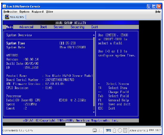
FIGURE 2-6 Redirection Screen Displaying BIOS Session
After you have configured the SP, you can configure or install your operating system.
The first time the server module is powered on, an automatic installation program displays a series of queries on the console. When it has the information it needs, it boots the system and configures the preinstalled Solaris operating system. The system should be ready to use.
This section describes how to connect to the system console, power on the server module, and complete the queries by the automatic installation program. You can complete this process using the SP over the network.
| Note - Before completing this procedure, fill out the worksheet in Appendix A. This information is required to configure the automatic installation program. |
|
|
1. Start the ILOM web interface as described in To Connect to the ILOM Web Interface.
2. Type the default user name and password.
The ILOM displays the System Information screen.
4. Click on the Remote Control tab.
The Launch Redirection screen appears.
The screen displays a number of dialog boxes.
| Note - For systems using Firefox and Mozilla web browsers, Java RTE must be version 1.6 or later. |
The web browser downloads the embedded remote control application automatically, and the Remote Console screen appears.
If the Remote Console does not appear, it might be blocked bythe browser’s security controls. Reduce security as required to enable the remote console.
6. Select Remote Control -> Remote Power Control.
The Power Control screen appears.
| Note - You can also turn on the system power manually. Use a non-conducting pointed object, such as a stylus, to press and release the Power button on the front panel. |
7. Select the Power On radio button, then click Submit.
The system displays the initial bootup messages, as shown in FIGURE 2-7.
FIGURE 2-7 Selections for Operating System

8. Use the arrow keys to scroll to the bottom line.
The line that reads Solaris 10 11/06 s10x_u3wos X86 (VGA) is highlighted.
The automatic installation program displays a series of queries.
10. Use the information in Appendix A to answer the queries.
When the automatic installation program has the information it needs, it posts a warning then reboots the system.
Each disk in your server can consume several watts while idle and spinning at full speed. If multiple disks (including external disks) are idle, the power cost can be significant.
The Solaris OS provides the ability to perform power management. It can be configured to automatically power off idle system components.
For more information, see the man pages for pmconfig(1M) and power.conf(4).
This section describes how to complete the initial setup of the factory-installed Microsoft Windows Server 2003 R2 operating system.
This section includes the following topics:
For additional information, see the Sun x64 Servers Windows Server 2003 R2 Operating System Preinstall Release Notes and the Sun x64 Servers Windows Server 2003 R2 Recovery Installation Guide.
Before proceeding, complete the physical installation of your system, including cabling. For installation procedures, see Inserting the Server Module.
You might also want to configure the disk drive holding the Windows operating system as part of a RAID array. As shipped, this drive is not configured for RAID. To make the disk part of a RAID array while preserving the data on the drive, add the drive to a mirrored RAID set (also known as hardware RAID Level 1).
When a Sun Blade RAID 5 Expansion Module is installed, SAS drives can be installed in disk slots 0 through 3. These disks can be configured as RAID 0, 1, 5, or 10.
For more information, see the Sun Intel Adaptec RAID User’s Guide.
You must establish one of the following console connections to the s server module to complete the initial setup of the factory-installed Windows operating system.
See To Access the System Console Using the ILOM Web Interface for details.
Follow these steps to boot the Windows factory-installed image, and to configure the initial Windows operating system settings for language, licensing, date and time, and network.
1. Reset the server or server module.
For reset instructions, refer to Routine Power On and Power Off.
The BIOS POST screen appears, then an EMS (Emergency Management Services) Detection dialog appears.
| Tip - If your mouse or keyboard is not responding, wait until the device(s) are properly detected. |
2. In the EMS Connection Detected dialog box, click OK to continue using this local connection.
The Welcome to Windows Setup dialog appears.
3. Click Next to continue the setup process and follow the onscreen instructions.
The following table summarizes the Windows Setup dialogs in the order in which they appear, as well as the actions required to complete them. For additional information, refer to the Getting Started Guide.
Once you have completed Windows Setup, the system will restart and automatically log in. Additional applications will be installed, the settings will be saved, and the system will restart. The initial setup is now completed.
The Sun Link application is included with your factory-installed Windows OS. You can access it from the Start menu and conveniently obtain x64 server updates, view online documentation, and install supplemental software (see FIGURE 2-8).
FIGURE 2-8 Sun Link Welcome Page

| Sun Blade X6250 Server Module Installation Guide | 820-1182-16 |
Copyright © 2009 Sun Microsystems, Inc. All rights reserved.

 To Insert the Server Module