| Logical Domains (LDoms) 1.1 Administration Guide |
| C H A P T E R 7 |
A virtual network allows domains to communicate with each other without using any external physical networks. A virtual network also can allow domains to use the same physical network interface to access a physical network and communicate with remote systems. A virtual network is created by having a virtual switch to which you can connect virtual network devices.
A virtual switch (vsw) is a component running in a service domain and managed by the virtual switch driver. A virtual switch can be connected to some guest domains to enable network communications between those domains. In addition, if the virtual switch is associated also with a physical network interface, then this allows network communications between guest domains and the physical network over the physical network interface. A virtual switch also has a network interface, vswn, where n is a number corresponding to the instance of the virtual switch, for example vsw0 for the first virtual switch in a service domain. This interface allows the service domain to communicate with the other domains connected to that virtual switch. It can be used like any regular network interface and configured with the ifconfig(1M) command.
Note - When a virtual switch is added to a service domain, its network interface is not plumbed. So, by default, the service domain is unable to communicate with the guest domains connected to its virtual switch. To enable network communications between guest domains and the service domain, the network interface of the associated virtual switch must be plumbed and configured in the service domain. See Enabling Networking Between the Control/Service Domain and Other Domains for instructions. |
A virtual network (vnet) device is a virtual device that is defined in a domain connected to a virtual switch. A virtual network device is managed by the virtual network driver, and it is connected to a virtual network through the hypervisor using logical domain channels (LDCs).
A virtual network device can be used as a network interface with the name vnetn, where n is a number corresponding to the instance of the virtual network device, and it can be used like any regular network interface and configured with the ifconfig(1M) command.
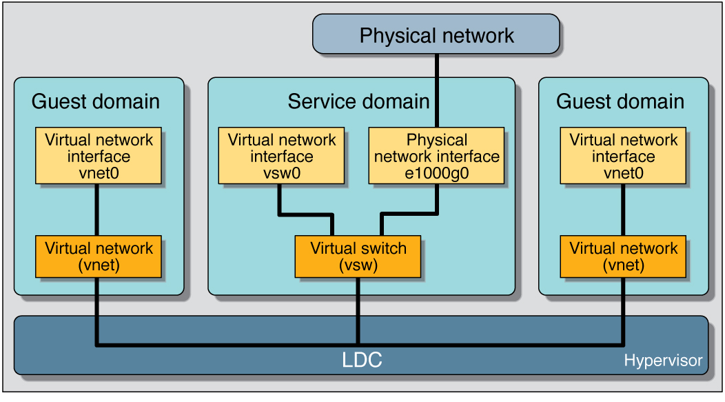
Following is a explanation for the example in Figure 6-1.
The virtual switch in the service domain is connected to the guest domains. This allows guest domains to communicate with each other.
The virtual switch also is connected to the physical network interface e1000g0. This allows guest domains to communicate with the physical network.
The virtual switch network interface vsw0 is plumbed in the service domain, so this allows the two guest domains to communicate with the service domain.
The virtual switch network interface vsw0 in the service domain can be configured using the ifconfig(1M) command.
The virtual network interfaces vnet0 in the guest domains can be configured using the ifconfig(1M) command.
Basically the virtual switch behaves like a regular physical network switch and switches network packets between the different systems, such as guest domains, service domain, and physical network, to which it is connected.
This section describes adding a virtual switch to a domain, setting options for a virtual switch, and removing a virtual switch.
Use the following command syntax to add a virtual switch.
# ldm add-vsw [default-vlan-id=vlan-id] [pvid=port-vlan-id] [vid=vlan-id1,vlan-id2,...] [mac-addr=num] [net-dev=device] [mode=sc] vswitch_name ldom |
default-vlan-id=vlan-id specifies the default virtual local area network (VLAN) to which a virtual switch and its associated virtual network devices belong to implicitly, in untagged mode. It serves as the default port VLAN id (pvid) of the virtual switch and virtual network devices. Without this option, the default value of this property is 1. Normally, you would not need to use this option. It is provided only as a way to change the default value of 1. See Using VLAN Tagging With Logical Domains Software for more information.
pvid=port-vlan-id specifies the VLAN to which the virtual switch needs to be a member, in untagged mode. See Using VLAN Tagging With Logical Domains Software for more information.
vid=vlan-id specifies one or more VLANs to which a virtual switch needs to be a member, in tagged mode. See Using VLAN Tagging With Logical Domains Software for more information.
mac-addr=num is the MAC address to be used by this switch. The number must be in standard octet notation; for example, 80:00:33:55:22:66. If you do not specify a MAC address, the switch is automatically assigned an address from the range of public MAC addresses allocated to the Logical Domains Manager. See Assigning MAC Addresses Automatically or Manually for more information.
net-dev=device is the path to the network device over which this switch operates.
mode=sc enables virtual networking support for prioritized processing of Solaris Cluster heartbeat packets in a Logical Domains environment. Applications like Solaris Cluster need to ensure that high priority heartbeat packets are not dropped by congested virtual network and switch devices. This option prioritizes Solaris Cluster heartbeat frames and ensures that they are transferred in a reliable manner.
You must set this option when running Solaris Cluster in a Logical Domains environment and using guest domains as Solaris Cluster nodes. Do not set this option when you are not running Solaris Cluster software in guest domains, because you could impact virtual network performance.
vswitch_name is the unique name of the switch that is to be exported as a service. Clients (network) can attach to this service.
ldom specifies the logical domain in which to add a virtual switch.
Use the following command syntax to set options for a virtual switch that already exists.
# ldm set-vsw [pvid=port-vlan-id] [vid=vlan-id1,vlan-id2,...] [mac-addr=num] [net-dev=device] [mode=[sc]] vswitch_name |
mode= (left blank) stops special processing of Solaris Cluster heartbeat packets.
Otherwise, the command arguments are the same as described in Add a Virtual Switch.
This section describes adding a virtual network device to a domain, setting options for an existing virtual network device, and removing a virtual network device.
Use the following command syntax to add a virtual network device.
# ldm add-vnet [mac-addr=num] [mode=hybrid] [pvid=port-vlan-id] [vid=vlan-id1,vlan-id2,...] if_name vswitch_name ldom |
mac-addr=num is the MAC address for this network device. The number must be in standard octet notation; for example, 80:00:33:55:22:66. See Assigning MAC Addresses Automatically or Manually for more information.
mode=hybrid to request the system to use NIU Hybrid I/O on this vnet if possible. If it is not possible, the system reverts to virtual I/O. This hybrid mode is considered a delayed reconfiguration if set on an active vnet. See Using NIU Hybrid I/O for more information.
pvid=port-vlan-id specifies the VLAN to which the virtual network device needs to be a member, in untagged mode. See Using VLAN Tagging With Logical Domains Software for more information.
vid=vlan-id specifies one or more VLANs to which a virtual network device needs to be a member, in tagged mode. See Using VLAN Tagging With Logical Domains Software for more information.
if_name, interface name, is a unique name to the logical domain, assigned to this virtual network device instance for reference on subsequent set-vnet or rm-vnet subcommands.
vswitch_name is the name of an existing network service (virtual switch) to which to connect.
ldom specifies the logical domain to which to add the virtual network device.
Use the following command syntax to set options for a virtual network device that already exists.
# ldm set-vnet [mac-addr=num] [vswitch=vswitch_name] [mode=[hybrid]] [pvid=port-vlan-id] [vid=vlan-id1,vlan-id2,...] if_name ldom |
if_name, interface name, is the unique name assigned to the virtual network device you want to set.
ldom specifies the logical domain from which to remove the virtual network device.
Otherwise, the command arguments are the same as described in Add a Virtual Network Device.
There is no way to determine the Solaris OS network interface name on a guest, corresponding to a given virtual device, directly from the output provided by the ldm list-* commands. However, you can do this by using a combination of the output from ldm list -l command and the entries under /devices on the Solaris OS guest.
In this example, guest domain ldg1 contains two virtual network devices, net-a and net-c. To find the Solaris OS network interface name in ldg1 that corresponds to net-c, do the following.
Use the ldm command to find the virtual network device instance for net-c.
# ldm list -l ldg1 ... NETWORK NAME SERVICE DEVICE MAC net-a primary-vsw0@primary network@0 00:14:4f:f8:91:4f net-c primary-vsw0@primary network@2 00:14:4f:f8:dd:68 ... # |
To find the corresponding network interface on ldg1, log into ldg1 and find the entry for this instance under /devices.
# uname -n ldg1 # find /devices/virtual-devices@100 -type c -name network@2\* /devices/virtual-devices@100/channel-devices@200/network@2:vnet1 # |
The network interface name is the part of the entry after the colon; that is, vnet1.
Plumb vnet1 to see that it has the MAC address 00:14:4f:f8:dd:68 as shown in the ldm list -l output for net-c in Step 1.
# ifconfig vnet1 vnet1: flags=1000842<BROADCAST,RUNNING,MULTICAST,IPv4> mtu 1500 index 3 inet 0.0.0.0 netmask 0 ether 0:14:4f:f8:dd:68 # |
You must have enough media access control (MAC) addresses to assign to the number of logical domains, virtual switches, and virtual networks you are going to use. You can have the Logical Domains Manager automatically assign MAC addresses to a logical domain, a virtual network (vnet), and a virtual switch (vsw), or you can manually assign MAC addresses from your own pool of assigned MAC addresses. The ldm subcommands that set MAC addresses are add-domain, add-vsw, set-vsw, add-vnet, and set-vnet. If you do not specify a MAC address in these subcommands, the Logical Domains Manager assigns one automatically.
The advantage to having the Logical Domains Manager assign the MAC addresses is that it utilizes the block of MAC addresses dedicated for use with logical domains. Also, the Logical Domains Manager detects and prevents MAC address collisions with other Logical Domains Manager instances on the same subnet. This frees you from having to manually manage your pool of MAC addresses.
MAC address assignment happens as soon as a logical domain is created or a network device is configured into a domain. In addition, the assignment is persistent until the device, or the logical domain itself, is removed.
Logical domains have been assigned the following block of 512K MAC addresses:
00:14:4F:F8:00:00 ~ 00:14:4F:FF:FF:FF
The lower 256K addresses are used by the Logical Domains Manager for automatic MAC address allocation, and you cannot manually request an address in this range:
00:14:4F:F8:00:00 - 00:14:4F:FB:FF:FF
You can use the upper half of this range for manual MAC address allocation:
When you do not specify a MAC address in creating logical domain or a network device, the Logical Domains Manager automatically allocates and assigns a MAC address to that logical domain or network device. To obtain this MAC address, the Logical Domains Manager iteratively attempts to select an address and then checks for potential collisions.
Before selecting a potential address, the Logical Domains Manager first looks to see if it has a recently freed, automatically assigned address saved in a database for this purpose (see Freed MAC Addresses). If so, the Logical Domains Manager selects its candidate address from the database.
If no recently freed addresses are available, the MAC address is randomly selected from the 256K range of addresses set aside for this purpose. The MAC address is selected randomly to lessen the chance of a duplicate MAC address being selected as a candidate.
The address selected is then checked against other Logical Domains Managers on other systems to prevent duplicate MAC addresses from actually being assigned. The algorithm employed is described in Duplicate MAC Address Detection. If the address is already assigned, the Logical Domains Manager iterates, choosing another address, and again checking for collisions. This continues until a MAC address is found that is not already allocated, or a time limit of 30 seconds has elapsed. If the time limit is reached, then the creation of the device fails, and an error message similar to the following is shown.
Automatic MAC allocation failed. Please set the vnet MAC address manually. |
To prevent the same MAC address from being allocated to different devices, one Logical Domains Manager checks with other Logical Domains Managers on other systems by sending a multicast message over the control domain’s default network interface, including the address that the Logical Domain Manager wants to assign to the device. The Logical Domains Manger attempting to assign the MAC address waits for one second for a response back. If a different device on another LDoms-enabled system has already been assigned that MAC address, the Logical Domains Manager on that system sends back a response containing the MAC address in question. If the requesting Logical Domains Manager receives a response, it knows the chosen MAC address has already been allocated, chooses another, and iterates.
By default, these multicast messages are sent only to other managers on the same subnet; the default time-to-live (TTL) is 1. The TTL can be configured using the Service Management Facilities (SMF) property ldmd/hops.
Each Logical Domains Manager is responsible for:
If the Logical Domains Manager on a system is shut down for any reason, duplicate MAC addresses could occur while the Logical Domains Manager is down.
Automatic MAC allocation occurs at the time the logical domain or network device is created and persists until the device or the logical domain is removed.
When a logical domain or a device associated with an automatic MAC address is removed, that MAC address is saved in a database of recently freed MAC addresses for possible later use on that system. These MAC addresses are saved to prevent the exhaustion of Internet Protocol (IP) addresses from a Dynamic Host Configuration Protocol (DHCP) server. When DHCP servers allocate IP addresses, they do so for a period of time (the lease time). The lease duration is often configured to be quite long, generally hours or days. If network devices are created and removed at a high rate without the Logical Domains Manager reusing automatically allocated MAC addresses, the number of MAC addresses allocated could soon overwhelm a typically configured DHCP server.
When a Logical Domains Manager is requested to automatically obtain a MAC address for a logical domain or network device, it first looks to the freed MAC address database to see if there is a previously assigned MAC address it can reuse. If there is a MAC address available from this database, the duplicate MAC address detection algorithm is run. If the MAC address had not been assigned to someone else since it was previously freed, it will be reused and removed from the database. If a collision is detected, the address is simply removed from the database. The Logical Domains Manager then either tries the next address in the database or if none is available, randomly picks a new MAC address.
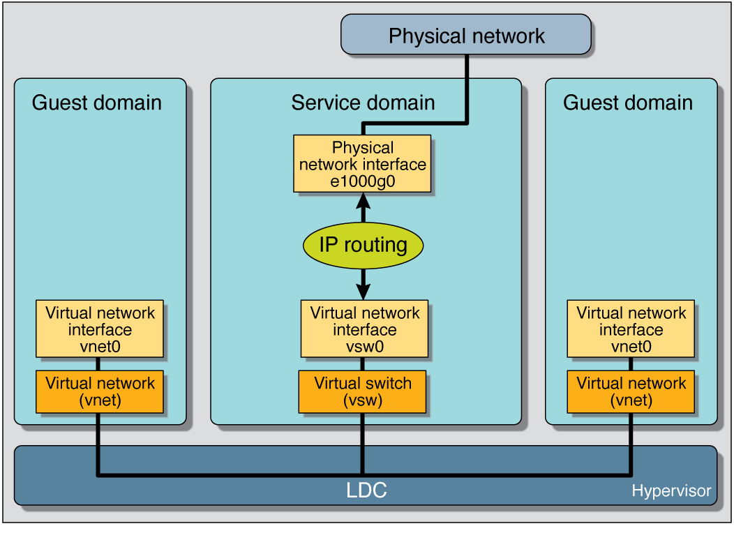
In a logical domains environment, the virtual switch service running in a service domain can directly interact with GLDv3-compliant network adapters. Though non-GLDv3 compliant network adapters can be used in these systems, the virtual switch cannot interface with them directly. See Configuring Virtual Switch and Service Domain for NAT and Routing for information about how to use non-GLDv3 compliant network adapters.
The virtual switch (vsw) is a layer-2 switch, that also can be used as a network device in the service domain. The virtual switch can be configured to act only as a switch between the virtual network (vnet) devices in the various logical domains but with no connectivity to a network outside the box through a physical device. In this mode, plumbing the vsw as a network device and enabling IP routing in the service domain enables virtual networks to communicate outside the box using the service domain as a router. This mode of operation is very essential to provide external connectivity to the domains when the physical network adapter is not GLDv3-compliant.
The advantages of this configuration are:
The virtual switch does not need to use a physical device directly and can provide external connectivity even when the underlying device is not GLDv3-compliant.
The configuration can take advantage of the IP routing and filtering capabilities of the Solaris OS.
|
Create a virtual switch with no associated physical device.
If assigning an address, ensure that the virtual switch has an unique MAC address.
primary# ldm add-vsw [mac-addr=xx:xx:xx:xx:xx:xx] primary-vsw0 primary |
Plumb the virtual switch as a network device in addition to the physical network device being used by the domain.
See Configure the Virtual Switch as the Primary Interface for more information about plumbing the virtual switch.
Configure the virtual switch device for DHCP, if needed.
See Configure the Virtual Switch as the Primary Interface for more information about configuring the virtual switch device for DHCP.
Configure IP routing in the service domain, and set up required routing tables in all the domains.
For information about how to do this, refer to the section on “Packet Forwarding and Routing on IPv4 Networks” in Chapter 5 “Configuring TCP/IP Network Services and IPv4 Administration” in the System Administration Guide: IP Services in the Solaris Express System Administrator Collection.
Internet Protocol Network Multipathing (IPMP) provides fault-tolerance and load balancing across multiple network interface cards. By using IPMP, you can configure one or more interfaces into an IP multipathing group. After configuring IPMP, the system automatically monitors the interfaces in the IPMP group for failure. If an interface in the group fails or is removed for maintenance, IPMP automatically migrates, or fails over, the failed interface’s IP addresses. In a Logical Domains environment, either the physical or virtual network interfaces can be configured for failover using IPMP.
A logical domain can be configured for fault-tolerance by configuring its virtual network devices to an IPMP group. When setting up an IPMP group with virtual network devices, in a active-standby configuration, set up the group to use probe-based detection. Link-based detection and failover currently are not supported for virtual network devices in Logical Domains 1.1 software.
The following diagram shows two virtual networks (vnet1 and vnet2) connected to separate virtual switch instances (vsw0 and vsw1) in the service domain, which, in turn, use two different physical interfaces (e1000g0 and e1000g1). In the event of a physical interface failure, the IP layer in LDom_A detects failure and loss of connectivity on the corresponding vnet through probe-based detection, and automatically fails over to the secondary vnet device.
Further reliability can be achieved in the logical domain by connecting each virtual network device (vnet0 and vnet1) to virtual switch instances in different service domains (as shown in the following diagram). Two service domains (Service_1 and Service_2) with virtual switch instances (vsw1 and vsw2) can be set up using a split-PCI configuration. In this case, in addition to network hardware failure, LDom_A can detect virtual network failure and trigger a failover following a service domain crash or shutdown.

Refer to the Solaris 10 System Administration Guide: IP Services for more information about how to configure and use IPMP groups.
If no explicit route is configured for a router in the network corresponding to the IPMP interfaces, then one or more explicit host routes to target systems need to be configured for the IPMP probe-based detection to work as expected. Otherwise, probe detection can fail to detect the network failures.
Network failure detection and recovery can also be set up in a Logical Domains environment by configuring the physical interfaces in the service domain into a IPMP group. To do this, configure the virtual switch in the service domain as a network device, and configure the service domain itself to act as an IP router. (Refer to the Solaris 10 System Administration Guide: IP Services for information on setting up IP routing).
Once configured, the virtual switch sends all packets originating from virtual networks (and destined for an external machine), to its IP layer, instead of sending the packets directly via the physical device. In the event of a physical interface failure, the IP layer detects failure and automatically re-routes packets through the secondary interface.
Since the physical interfaces are directly being configured into a IPMP group, the group can be set up for either link-based or probe-based detection. The following diagram shows two network interfaces (e1000g0 and e1000g1) configured as part of an IPMP group. The virtual switch instance (vsw0) has been plumbed as a network device to send packets to its IP layer.

As of the release of Solaris 10 10/08 OS and LDoms 1.1 software, 802.1Q VLAN-Tagging support is available in the Logical Domains network infrastructure.
Note - Tagged VLANs are not supported in any of the previous releases for LDoms networking components. |
The virtual switch (vsw) and virtual network (vnet) devices support switching of Ethernet packets based on the virtual local area network (VLAN) identifier (ID) and handle the necessary tagging or untagging of Ethernet frames.
You can create multiple VLAN interfaces over a vnet device in a guest domain. You can use the Solaris OS ifconfig(1M) command to create a VLAN interface over a virtual network device, the same way it is used to configure a VLAN interface over any other physical network device. The additional requirement in the LDoms environment is that you must assign the vnet to the corresponding VLANs using the Logical Domains Manager CLI commands. Refer to the ldm(1M) man page or the Logical Domains (LDoms) Manager 1.1 Man Page Guide for complete information about the Logical Domains Manager CLI commands.
Similarly, you can configure VLAN interfaces over a virtual switch device in the service domain. VLAN IDs 2 through 4094 are valid; VLAN ID 1 is reserved as the default-vlan-id.
When you create a vnet device on a guest domain, you must assign it to the required VLANs by specifying a port VLAN ID and zero or more VLAN IDs for this vnet, using the pvid= and vid= arguments to the ldm add-vnet command. This configures the virtual switch to support multiple VLANs in the LDoms network and switch packets using both MAC address and VLAN IDs in the network.
Similarly, any VLANs to which the vsw device itself should belong, when plumbed as a network interface, must be configured in the vsw device using the pvid= and vid= arguments to the ldm add-vsw command.
You can change the VLANs to which a device belongs using ldm set-vnet or ldm set-vsw command.
The PVID indicates a VLAN to which the virtual network device needs to be a member, in untagged mode. In this case, the vsw device provides the necessary tagging or untagging of frames for the vnet device over the VLAN specified by its PVID. Any outbound frames from the virtual network that are untagged are tagged with its PVID by the virtual switch. Inbound frames tagged with this PVID are untagged by the virtual switch, before sending it to the vnet device. Thus, assigning a PVID to a vnet implicitly means that the corresponding virtual network port on the virtual switch is marked untagged for the VLAN specified by the PVID. You can have only one PVID for a vnet device.
The corresponding virtual network interface, when configured using the ifconfig(1M) command without a VLAN ID and using only its device instance, results in the interface being implicitly assigned to the VLAN specified by the virtual network’s PVID.
For example, if you were to plumb vnet instance 0, using the following command, and if the pvid= argument for the vnet has been specified as 10, the vnet0 interface would be implicitly assigned to belong to the VLAN 10.
# ifconfig vnet0 plumb |
The VID indicates the VLAN to which a virtual network device or virtual switch needs to be a member, in tagged mode. The virtual network device sends and receives tagged frames over the VLANs specified by its VIDs. The virtual switch passes any frames that are tagged with the specified VID between the virtual network device and the external network.
Assign the virtual switch (vsw) to two VLANs, for example. Configure VLAN 21 as untagged and VLAN 20 as tagged. Assign the virtual network (vnet) to three VLANs, for example. Configure VLAN 20 as untagged and VLAN 21 and 22 as tagged.
# ldm add-vsw net-dev=e1000g0 pvid=21 vid=20 primary-vsw0 primary # ldm add-vnet vnet01 primary-vsw0 pvid=20 vid=21,22 ldom1 |
This example assumes that the instance number of these devices is 0 in the domains and the VLANs are mapped to these subnets:
| VLAN | Subnet |
|---|---|
| 20 | 192.168.1.0 (netmask: 255.255.255.0) |
| 21 | 192.168.2.0 (netmask: 255.255.255.0) |
| 22 | 192.168.3.0 (netmask: 255.255.255.0) |
Plumb the VLAN interface in the service (primary) domain.
primary# ifconfig vsw0 plumb primary# ifconfig vsw0 192.168.2.100 netmask 0xffffff00 broadcast + up primary# ifconfig vsw20000 plumb primary# ifconfig vsw20000 192.168.1.100 netmask 0xffffff00 broadcast + up |
Plumb the VLAN interface in the guest (ldom1) domain.
ldom1# ifconfig vnet0 plumb ldom1# ifconfig vnet0 192.168.1.101 netmask 0xffffff00 broadcast + up ldom1# ifconfig vnet21000 plumb ldom1# ifconfig vnet21000 192.168.2.101 netmask 0xffffff00 broadcast + up ldom1# ifconfig vnet22000 plumb ldom1# ifconfig vnet22000 192.168.3.101 netmask 0xffffff00 broadcast + up |
For more information about how to configure VLAN interfaces in the Solaris OS, refer to "Administering Virtual Local Area Networks" in the Solaris System Administration Guide: IP Services.
LDoms 1.1 virtual I/O framework implements a hybrid I/O model for improved functionality and performance. The hybrid I/O model combines direct and virtualized I/O to allow flexible deployment of I/O resources to virtual machines. It is particularly useful when direct I/O does not provide full capability for the virtual machine, or direct I/O is not persistently or consistently available to the virtual machine. This could be because of resource availability or virtual machine migration. The hybrid I/O architecture is well-suited to the Network Interface Unit (NIU), a network I/O interface integrated on chip, on Sun UltraSPARC T2–based platforms. This allows the dynamic assignment of Direct Memory Access (DMA) resources to virtual networking devices and, thereby, provides consistent performance to applications in the domain.
As of the release of Solaris 10 10/08 OS and LDoms 1.1 software, NIU hybrid I/O is available for Sun UltraSPARC T2–based platforms. This feature is enabled by an optional hybrid mode that provides for a virtual network (vnet) device where the DMA hardware resources are loaned to a vnet device in a guest domain for improved performance. In the hybrid mode, a vnet device in a guest domain can send and receive unicast traffic from an external network directly into the guest domain using the DMA hardware resources. The broadcast traffic and unicast traffic to the other guest domains in the same system continue to be sent using the virtual I/O communication mechanism.

The hybrid mode applies only for the vnet devices that are associated with a virtual switch (vsw) configured to use an NIU network device. As the shareable DMA hardware resources are limited, up to only three vnet devices per vsw can have DMA hardware resources assigned at a given time. If more than three vnet devices have the hybrid mode enabled, the assignment is done on a first-come, first-served basis. As there are two NIU network devices in a system, there can be a total of six vnet devices on two different virtual switches with DMA hardware resources assigned.
Following are points you need to be aware of when using this feature:
Hybrid mode option for a vnet device is treated as a suggestion only. That means the DMA resources are assigned only when they are available and the device is capable of using them.
Logical Domains Manager CLI commands do not validate the hybrid mode option; that is, it is possible to set the hybrid mode on any vnet or any number of vnet devices.
Guest domains and the service domain need to run Solaris 10 10/08 OS at a minimum.
Up to a maximum of only three vnet devices per vsw can have DMA hardware resources loaned at a given time. As there are two NIU network devices, there can be a total of six vnet devices with DMA hardware resources loaned.
Note - Set the hybrid mode only for three vnet devices per vsw so that they are guaranteed to have DMA hardware resources assigned. |
Hybrid mode is disabled by default for a vnet device. It needs to be explicitly enabled with Logical Domains Manager CLI commands. See Enable Hybrid Mode.
(Refer to the Logical Domains (LDoms) Manager 1.1 Man Page Guide or the ldm man page for more details.)
The hybrid mode option cannot be changed dynamically while the guest domain is active.
The DMA hardware resources are assigned only when a vnet device is active that is plumbed in the guest domain.
The Sun x8 Express 1/10G Ethernet Adapter (nxge) driver is used for the NIU card, but the same driver is also used for other 10-gigabit network cards. However, the NUI hybrid I/O feature is available for NIU network devices only.
| Logical Domains (LDoms) 1.1 Administration Guide | 820-4913-10 |
Copyright © 2008, Sun Microsystems, Inc. All rights reserved.
 Add a Virtual Switch