Hardware Tab
Note –
The Hardware tab does not appear if this feature is not supported on your system.
The Hardware Details window, which is shown in Figure 6–2, provides three choices for system information:
-
Hardware Summary
-
Physical View
-
Logical View
Note –
For additional information about the Hardware tab for your specific hardware object, see your platform supplement.
Figure 6–2 Hardware Details Window
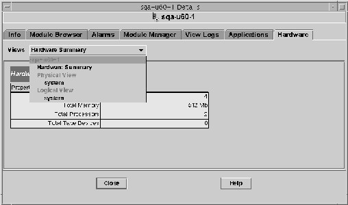
The Views menu provides access to the available hardware information.
Hardware Summary
The Sun Management Center software displays a table of hardware resources of the selected host. The following list shows some typical values displayed in the Hardware Summary.
- Total Disks
- Total Memory
- Total Processors
- Total Tape Devices
-
Total number of tape devices that are connected to the host
Your summary might appear different. The resources vary, depending on the type of object that is displayed in the detail view.
Note –
The Total Disks field displays the number of internal disks only. This number does not include the disks that are part of enclosures.
Physical View
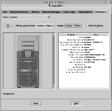
When you select the Physical view - system option, the software displays a photo-realistic picture of the selected host, if available. Pictures are not available for some system types.
Note –
This feature is usable only if the host is monitored by a Sun Management Center agent.
As you move the mouse pointer over the picture of the system being viewed, some of the components are highlighted. The detailed component information displays in the right section of the viewing window. The path name of the component is displayed in the Component field at the bottom of the window.
If a component has an alarm, a colored line appears around the component to indicate the alarm severity. This line enables you to identify quickly the faulty component.
Figure 6–3 Hardware Configuration Physical View With Component Details (Property/Value View)
Rotate Current View Menu
For some systems, you can select alternate front, rear, and side views through the Rotate Current View pull-down menu. Pictures are not available for some system types.
For some systems, pictures of components such as CPU boards and I/O boards might also be available. As you move the mouse pointer over the system picture, the pointer changes from an arrow to a hand icon when there is an individual component picture.
Click a highlighted component to display the detailed picture of the component. When you are finished viewing component details, click Up to return to the parent system view.
Physical View When a Sun StorEdge Device is Connected
If a Sun StorEdge™ A5000, A5100, A5200, or T3 system is connected to the selected component, the Views pull-down menu lists the devices that are connected. The connected devices are listed under the system to which they are connected. The Sun StorEdge A5000-series devices are displayed on this menu as sena(0), sena(1), and so on.
You can select and view any of these storage devices from the Views menu.
History Menu
Use the History pull-down menu to revisit a view that you had selected previously.
Refresh Details Button
Click the Refresh Details button to update the Property/Value information in the right side of the Details window for the selected physical component. Otherwise, the information does not change from when you first opened the physical view.
Dynamic Reconfiguration Button
The Dynamic Reconfiguration button appears in the physical view and in the logical view only for certain platforms. Refer to your hardware supplement for more information.
Logical View
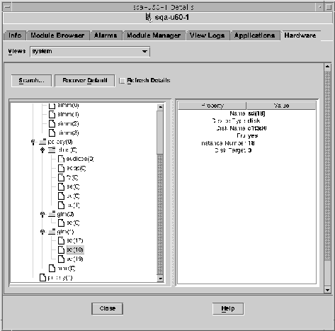
The software displays a logical view configuration of a host, if the host is monitored by a Sun Management Center agent, as illustrated in the following figure. Logical views are not available for ping hosts.
Figure 6–4 Hardware Configuration Logical View
Search Button
Click the Search button to display the Search window. Use the Search window to search for components in the Logical View topology on the left side of the viewing window. The located component is highlighted in the topology view. The name of the component displays in the Component field in the bottom right section of the screen.
The Search function is case-sensitive. If the search does not locate the component in your system, the following error message appears at the bottom of the Details window.
Node not found |
The Search function stops at the first instance found. For example, if you enter the word board, Search always stops at board(0). To find the next hit, click the Next button. To find a specific instance of a name, type a more complete name. For example, board(2).
Expand All
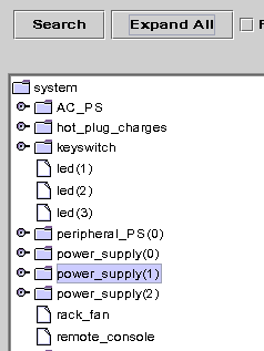
Click the Expand All/Recover Default button to decompress and recompress all the component icons in the topology area (left side) of the window. The compressed view is shown in the following figure.
Figure 6–5 Compressed Topology of Components in Logical View
Press the Expand All button to display the expanded topology view, as shown in the following figure.
Figure 6–6 Expanded Topology of Components in Logical View
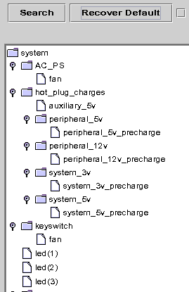
The button label toggles to Recover Default. When you press Recover Default, the topology recompresses all the component icons in the topology area of the window.
Refresh Details and Dynamic Reconfiguration
The Refresh Details and Dynamic Reconfiguration features in the Logical View are the same as the features described for the Physical View in Refresh Details Button and Dynamic Reconfiguration Button.
- © 2010, Oracle Corporation and/or its affiliates
