Chapter 4 Preparing to Install or Replace Parts
This chapter tells you what you need to know, and need to do, before opening the system to install, remove, or replace parts.
Tasks covered in this chapter include:
Other information covered in this chapter includes:
How to Power Off the System
Before turning off system power, halt the operating system as described below. Failure to halt the operating system properly can result in loss of disk drive data.
What to Do
-
Notify users that the system will be powered down.
-
Back up the system files and data, if necessary.
-
Halt the operating system using the appropriate commands.
Refer to the Solaris Handbook for SMCC Peripherals that corresponds to your operating system.
-
Wait for the system halt messages and the ok prompt.
-
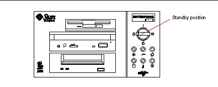
Turn the keyswitch on the front panel of the system to the Standby position, which is fully counterclockwise.
Figure 4-1
How to Power On the System
Before You Begin
If a terminal or local console is not already connected to the system, you need to install one before continuing the startup procedure.
Note -
Do not use this power-on procedure if you have just installed an internal or external storage device, or any new part that plugs into the main logic board. To power on the system after adding any of these options, see "How to Initiate a Reconfiguration Boot".
What to Do
Never move the system when system power is on. Movement can cause catastrophic disk drive failure. Always power off the system before moving it.
Before you power on the system, make sure that the side access panel and all plastic outer panels and doors are properly installed.
Removing the side access panel or removable media assembly activates the system power interlock switches. This safety mechanism prevents all DC voltages (except 5V standby power) from reaching any internal component when the side panel or removable media assembly is removed and the front panel keyswitch is in the Power-on position.
-
Turn on power to any peripherals and external storage devices.
Read the documentation supplied with the device for specific instructions.
-
Turn on power to the monitor or terminal.
A terminal or monitor is required for viewing system messages. For setup instructions, see "How to Attach an Alphanumeric Terminal" or "How to Configure a Local Graphics Console".
-
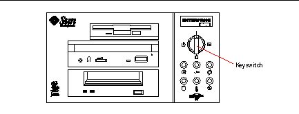
Turn the front panel keyswitch to the Power-on, Diagnostics, or Locked position.
See "About the Status and Control Panel" for information about each keyswitch setting.
Figure 4-2
Note -The system may take anywhere from 30 seconds to two minutes before video is displayed on the system monitor or the ok prompt appears on an attached terminal. This time depends on the level of power-on self-test (POST) diagnostics being performed.
How to Initiate a Reconfiguration Boot
Before You Begin
After installing any new part that plugs into the main logic board or any internal or external storage device, you must perform a reconfiguration boot so that your system is able to recognize the newly installed option(s).
Before you power on the system, make sure that the side access panel and all plastic outer panels and doors are properly installed.
Removing the side access panel or removable media assembly activates the system power interlock switches. This safety mechanism prevents all DC voltages (except 5V standby power) from reaching any internal component when the side panel or removable media assembly is removed and the front panel keyswitch is in the Power-on position.
What to Do
-
Turn on power to any peripherals and external storage devices.
Read the documentation supplied with the device for specific instructions.
-
Turn on power to the monitor or terminal.
A terminal or monitor is required for viewing system messages. For setup instructions, see "How to Attach an Alphanumeric Terminal" or "How to Configure a Local Graphics Console".
-
Turn the front panel keyswitch to the Power-on position or to the Diagnostics position.
See "About the Status and Control Panel".
Use the Diagnostics position to run POST and OpenBoot Diagnostic tests to verify that the system functions correctly with the new part(s) you have just installed. For additional information, see Chapter 12, Diagnostics and Troubleshooting.
-
When the system banner is displayed on the monitor or terminal, immediately enter the Stop-a sequence on the Sun keyboard or press the Break key on the terminal keyboard.
The system banner contains the Ethernet address and host ID. To enter the Stop-a sequence, hold down the Stop key and press the a key.
Note -The system may take anywhere from 30 seconds to two minutes before the system banner appears. This time depends on the level of power-on self-test diagnostics being performed.
-
When the ok prompt is displayed, enter the following command:
ok boot -r
This command rebuilds the device trees for the system, incorporating any newly installed options. After a device has been added to a device tree, it can be recognized by the system. After the reconfiguration reboot has successfully completed, the system prompt should be displayed.
 Caution -
 Never move the system when system power is on. Movement can cause catastrophic disk drive failure. Always power off the system before moving it.
What Next
The system's front panel LED indicators provide power-on status information. For more information about the system LEDs, see:
How to Remove the Side Access Panel
Do not operate the system while any of its plastic outer panels or doors are removed.
Removing the side access panel or removable media assembly activates the system power interlock switches. This safety mechanism prevents all DC voltages (except 5V standby power) from reaching any internal component when the side panel or removable media assembly is removed and the front panel keyswitch is left on. Do not remove the side access panel or removable media assembly while the system is operating or the system will power off abruptly.
Before You Begin
Complete this task:
Video Demonstration
Figure 4-3

Click on the icon above for a video demonstration.
Click here for Appendix E, Video Player Help.
What to Do
-
Remove the security lock block (if present).
-
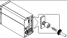
Loosen the two captive screws securing the side panel to the rear of the chassis.
Figure 4-4
-
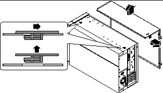
Pull the side panel toward the back of the system.
Carefully disengage the hooks securing the side panel to the top of the chassis.
Figure 4-5
-
Lift the side panel up and away from the system, and set the panel aside.
What Next
You are now ready to install, remove, or replace components inside the system chassis.
How to Install the Side Access Panel
Before You Begin
Remember to detach the antistatic wrist or foot strap from the system chassis sheet metal.
Video Demonstration
Figure 4-6

Click on the icon above for a video demonstration.
Click here for Appendix E, Video Player Help.
What to Do
-
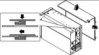
Locate the hooks beneath the top surface of the side panel and insert them into the slots in the top of the system chassis.
Figure 4-7
-
Slide the panel toward the front of the system until it contacts the system's plastic front panel.
-
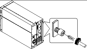
Tighten the two captive Phillips screws that secure the side panel to the rear of the chassis.
Figure 4-8
-
Replace the security lock block (if required).
What Next
When you're ready to restart the system, see:
How to Avoid Electrostatic Discharge
Use the following procedure to prevent static damage whenever you are accessing any of the internal components of the system.
Before You Begin
Complete this task:
You must have the following items:
-
Antistatic wrist or foot strap
-
Antistatic mat (or the equivalent)
What to Do
Printed circuit boards and hard disk drives contain electronic components that are extremely sensitive to static electricity. Ordinary amounts of static from your clothes or the work environment can destroy components. Do not touch the components themselves or any metal parts without taking proper antistatic precautions.
-
Disconnect the AC power cord from the wall power outlet only if you will be handling the power distribution board.
The AC power cord provides a discharge path for static electricity, so you generally want to leave it plugged in during installation and repair procedures. The only time you should unplug the cord is when you service the power distribution board.
-
Use an antistatic mat or similar surface.
When performing any option installation or service procedure, place static-sensitive parts, such as boards, cards, and disk drives, on an antistatic surface. The following items can be used as an antistatic surface:
-
The bag used to wrap a Sun(TM) replacement part
-
The shipping container used to package a Sun replacement part
-
Sun electrostatic discharge (ESD) mat, PN 250-1088 (available through your Sun sales representatives)
-
Disposable ESD mat, shipped with replacement parts or options
-
-
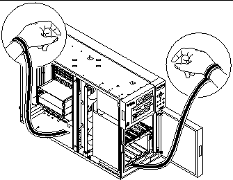
Use an antistatic wrist strap.
Attach the appropriate end to the system chassis sheet metal, and attach the other end of the strap to your wrist. Refer to the instructions that come with the strap.
Figure 4-9
-
Detach both ends of the strap after you have completed the installation or service procedure.
Reference for Installation and Service: Tools Required
The following tools are required to install and service the system:
-
Screwdriver, Phillips #1
-
Screwdriver, Phillips #2
-
Screwdriver, long flat-blade #2
-
ESD mat, Sun PN 250-1088, or equivalent
-
Grounding wrist or foot strap
The latter two items help protect the server against damage due to electrostatic discharge. For more information, see "How to Avoid Electrostatic Discharge".
- © 2010, Oracle Corporation and/or its affiliates
