Chapter 5 Hardware Configuration
This chapter describes the hardware configuration of the system. Topics covered in this chapter include:
About Reliability, Availability, and Serviceability Features
Reliability, availability, and serviceability are aspects of a system's design that affect its ability to operate continuously and minimize the time necessary to service the system. Reliability refers to a system's ability to operate continuously without failures and to maintain data integrity. System availability refers to the percentage of time that a system remains accessible and usable. Serviceability relates to the time it takes to restore a system to service following a system failure. Together, reliability, availability, and serviceability provide for near continuous system operation.
To deliver high levels of reliability, availability and serviceability, the system offers the following features:
-
Error correction and parity checking for improved data integrity
-
Easily accessible status indicators
-
Hot-pluggable disk drives
-
Support for RAID 0, 1, and 5 storage configurations
-
Environmental monitoring and fault protection
-
N+1 power supply redundancy
-
Hot-swappable power supplies
-
Automatic system recovery (ASR)
-
Hardware watchdog mechanism
-
Four different levels of system diagnostics
-
Remote System Control (RSC)
Error Correction and Parity Checking
Error correcting code (ECC) is used on all internal system data paths to ensure high levels of data integrity. All data that moves between processors, I/O, and memory have end-to-end ECC protection.
The system reports and logs correctable ECC errors. A correctable ECC error is any single-bit error in a 64-bit field. Such errors are corrected as soon as they are detected. The ECC implementation can also detect double-bit errors in the same 64-bit field and multiple-bit errors in the same nibble (4 bits).
In addition to providing ECC protection for data, the system offers parity protection on all system address buses. Parity protection is also used on the PCI and SCSI buses, and in the UltraSPARC CPU's internal and external cache.
Status LEDs
The system provides easily accessible light-emitting diode (LED) indicators on the system front panel, internal disk bays, and power supplies to provide a visual indication of system and component status. Status LEDs eliminate guesswork and simplify problem diagnosis for enhanced serviceability.
Status and control panel LEDs are described in "About the Status and Control Panel". Disk drive and power supply LEDs are described in "Error Indications".
Hot-Pluggable Disk Drives
The "hot-plug" feature of the system's internal disk drives permits the removal and installation of drives while the system is operational. All drives are easily accessed from the front of the system. Hot-plug technology significantly increases the system's serviceability and availability, by providing the ability to:
-
Increase storage capacity dynamically to handle larger work loads and improve system performance.
-
Replace disk drives without service disruption.
For more information about hot-pluggable disk drives, see "About Internal Disk Drives" and "About Disk Array Configurations and Concepts".
Support for RAID 0, RAID 1, and RAID 5 Disk Configurations
The Solstice DiskSuite software designed for use with the system provides the ability to configure system disk storage in a variety of different RAID levels. You choose the appropriate RAID configuration based on the price, performance, and reliability/availability goals for your system.
RAID 0 (striping), RAID 1 (mirroring), RAID 0+1 (striping plus mirroring) and RAID 5 configurations (striping with interleaved parity) can all be implemented using Solstice DiskSuite. You can also configure one or more drives to serve as "hot spares" to fill in automatically for a defective drive in the event of a disk failure.
For more information about RAID configurations, see "About Disk Array Configurations and Concepts".
Environmental Monitoring and Control
The system features an environmental monitoring subsystem designed to protect against:
-
Extreme temperatures
-
Lack of air flow through the system
-
Power supply problems
Monitoring and control capabilities reside at the operating system level as well as in the system's flash PROM firmware. This ensures that monitoring capabilities are operational even if the system has halted or is unable to boot.
The environmental monitoring subsystem uses an industry standard I2C bus implemented on the main logic board. The I2C bus is a simple two-wire serial bus, used throughout the system to allow the monitoring and control of temperature sensors, fans, power supplies, and status LEDs.
Temperature sensors are located throughout the system to monitor the ambient temperature of the system and the temperature of each CPU module. The monitoring subsystem frequently polls each sensor and uses the sampled temperatures to:
-
Regulate fan speeds for maintaining an optimum balance between proper cooling and noise levels.
-
Report and respond to any over-temperature conditions.
To indicate an over-temperature condition, the monitoring subsystem generates a warning message, and depending on the nature of the condition, may even shut down the system. If a CPU module reaches 60 degrees C or the ambient temperature reaches 53 degrees C, the system generates a warning message and illuminates the temperature fault LED on the status and control panel. If a CPU module reaches 65 degrees C or the ambient temperature reaches 58 degrees C, the system is automatically shut down.
This thermal shutdown capability is also built into the main logic board circuitry as a fail-safe measure. This feature provides backup thermal protection in the unlikely event that the environmental monitoring subsystem becomes disabled at both the software and firmware levels.
All error and warning messages are displayed on the system console (if one is attached) and are logged in the /var/adm/messages file. Front panel fault LEDs remain lit after an automatic system shutdown to aid in problem diagnosis.
The monitoring subsystem is also designed to detect fan failures. The system includes three fans, part of a single assembly called the fan tray assembly. Any fan failure causes the monitoring subsystem to generate an error message and light the general fault LED on the status and control panel.
The power subsystem is monitored in a similar fashion. The monitoring subsystem periodically polls the power supply status registers for a power supply OK status, indicating the status of each supply's +2.5V, +3.3V, +5V, +12V, and -12V DC outputs.
If a power supply problem is detected, an error message is displayed on the console (if one is attached) and logged in the /var/adm/messages file. The power supply LED on the status and control panel is also lit. The LEDs located on the power supply itself will indicate the type of fault, and if two power supplies are installed, will indicate which supply is the source of the fault.
For more information about error messages generated by the environmental monitoring subsystem, see "Environmental Failures". For additional details about the status and control panel LEDs, see "About the Status and Control Panel".
N+1 Power Supply Redundancy
The system can accommodate one or two power supplies. All system configurations can operate with only one power supply installed. A second supply can be used to provide N+1 redundancy, allowing the system to continue operating should one of the power supplies fail.
For more information about power supplies, redundancy, and configuration rules, see "About Power Supplies".
Hot-Swappable Power Supplies
Power supplies in a redundant configuration feature a "hot-swap" capability. You can remove and replace a faulty power supply without turning off the system power or even shutting down the operating system. The power supplies are easily accessed from the rear of the system, without the need to remove system covers.
Automatic System Recovery (ASR)
The system provides for automatic system recovery (ASR) from the following types of hardware component failures:
-
CPU modules
-
Memory modules
-
PCI buses
-
System I/O interfaces
The automatic system recovery feature allows the system to resume operation after experiencing certain hardware faults or failures. Automatic self-test features enable the system to detect failed hardware components and an auto-configuring capability designed into the system's boot firmware allows the system to deconfigure failed components and restore system operation. As long as the system is capable of operating without the failed component, the ASR features will enable the system to reboot automatically, without operator intervention.
During the power-on sequence, if a faulty component is detected, the component is effectively disabled and, if the system remains capable of functioning, the boot sequence continues. In a running system, some types of failures (such as a processor failure) will usually bring the system down. If this happens, the ASR functionality enables the system to reboot immediately if it is possible for the system to function without the failed component. This prevents a faulty hardware component from keeping the entire system down or causing the system to crash again.
Control over the system's ASR functionality is provided by a number of OpenBoot PROM commands. These are described in the document Platform Notes: Sun Enterprise 250 Server, available on the Solaris on Sun Hardware AnswerBook. This AnswerBook documentation is provided on the SMCC Supplement CD for the Solaris release you are running.
Hardware Watchdog Mechanism
To detect and respond to system hang conditions, the Enterprise 250 server features a hardware watchdog mechanism--a hardware timer that is continually reset as long as the operating system is running. In the event of a system hang, the operating system is no longer able to reset the timer. The timer will then expire and cause an automatic system reset, eliminating the need for operator intervention.
Note -
The hardware watchdog mechanism is not activated until you enable it.
To enable this feature, you must edit the /etc/system file to include the following entry:
set watchdog_enable = 1
This change does not take effect until you reboot the system.
Four Levels of Diagnostics
For enhanced serviceability and availability, the system provides four different levels of diagnostic testing: power-on self-test (POST), OpenBoot diagnostics (OBDiag), SunVTS(TM), and Solstice(TM) SyMON(TM).
POST and OBDiag are firmware-resident diagnostics that can run even if the server is unable to boot the operating system. Application-level diagnostics, such as SunVTS and Solstice SyMON, offer additional troubleshooting capabilities once the operating system is running.
POST diagnostics provide a quick but thorough check of the most basic hardware functions of the system. For more information about POST, see "About Power-On Self-Test (POST) Diagnostics" and "How to Use POST Diagnostics".
OBDiag provides a more comprehensive test of the system, including external interfaces. OBDiag is described in "About OpenBoot Diagnostics (OBDiag)" and "How to Use OpenBoot Diagnostics (OBDiag)".
At the application level, you have access to SunVTS diagnostics. Like OBDiag, SunVTS provides a comprehensive test of the system, including its external interfaces. SunVTS also allows you to run tests remotely over a network connection. You can only use SunVTS if the operating system is running. For more information about SunVTS, see "About SunVTS Software", "How to Use SunVTS Software", and "How to Check Whether SunVTS Software Is Installed".
Another application-level program, called Solstice SyMON, provides you with a variety of continuous system monitoring capabilities. It allows you to monitor system hardware status and operating system performance of your server. For more information about SyMON, see "About Solstice SyMON Software".
Remote System Control (RSC)
Remote System Control (RSC) is a secure server management tool that lets you monitor and control your server over modem lines or over a network. RSC provides remote system administration for geographically distributed or physically inaccessible systems. The RSC software works with the System Service Processor (SSP) on the Enterprise 250 main logic board. The RSC and SSP support both serial and Ethernet connections to a remote console.
Once RSC is configured to manage your server, you can use it to run diagnostic tests, view diagnostic and error messages, reboot your server, and display environmental status information from a remote console. If the operating system is down, RSC will notify a central host of any power failures, hardware failures, or other important events that may be occurring on your server.
The RSC provides the following features:
-
Remote system monitoring and error reporting (including diagnostic output)
-
Remote reboot on demand
-
Ability to monitor system environmental conditions remotely
-
Ability to run diagnostic tests from a remote console
-
Remote event notification for over-temperature conditions, power supply failures, fatal system errors, or system crashes
-
Remote access to detailed event logs
-
Remote console functions on serial and ethernet ports
For information about configuring and using RSC, see the Remote System Control (RSC) User's Guide, provided with the RSC software.
About Memory
Figure 5-1
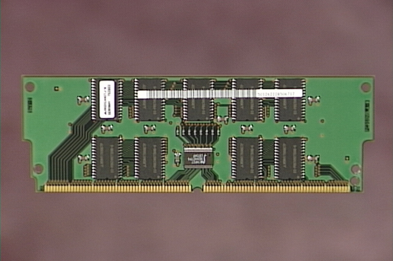
The system's main logic board provides sixteen slots for high-capacity dual inline memory modules (DIMMs). The system supports Sun standard 200-pin, 5-volt, 60-nanosecond memory modules. Modules of 32-, 64-, and 128-Mbyte capacities can be installed in the system. Total system memory capacity ranges from 128 Mbytes to 2 Gbytes.
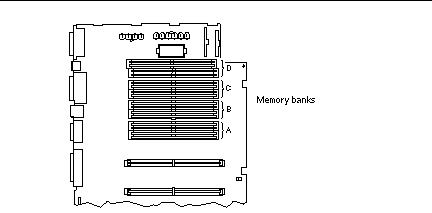
Memory slots are organized into four banks, with each bank comprising four slots. The system reads from, or writes to, all four DIMMs in a bank at the same time. DIMMs, therefore, must be added four at a time in the same bank. The following figure shows the memory banks on the main logic board.
Figure 5-2
Configuration Rules
Memory DIMMs must be added four at a time within the same bank, and each bank used must have four identical capacity DIMMs installed (for example, four 32-Mbyte DIMMs, or four 64-Mbyte DIMMs).
Memory bank A must always be filled.
DIMM capacities can differ from one bank to the next--for example, four 32-Mbyte DIMMs installed in bank A and four 64-Mbyte DIMMs installed in bank B.
Memory modules are delicate. Be sure to take appropriate precautions to avoid damaging them through electrostatic discharge. For more information, see "How to Avoid Electrostatic Discharge".
Dual inline memory modules (DIMMs) are made of electronic components that are extremely sensitive to static electricity. Static from your clothes or work environment can destroy the modules. Do not remove any DIMM from its antistatic packaging until you are ready to install it on the system board. Handle the modules only by their edges. Do not touch the components or any metal parts. Always wear a grounding strap when you handle the modules.
About CPU Modules
Figure 5-3
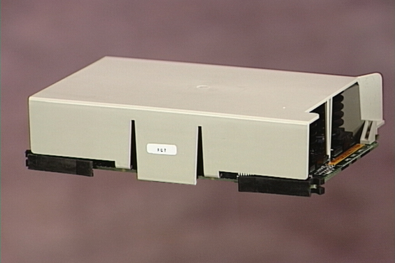
The UltraSPARC II CPU module is a high-performance, highly-integrated superscalar processor implementing the SPARC-V9 64-bit RISC architecture. The UltraSPARC II processor supports both 2-D and 3-D graphics, as well as image processing, video compression and decompression, and video effects through the sophisticated visual instruction set (VIS). VIS provides high levels of multimedia performance, including real-time video compression/decompression and two streams of MPEG-2 decompression at full broadcast quality with no additional hardware support.
The system's main logic board provides slots for two UltraSPARC II CPU modules. Each processor module includes one CPU chip with integrated cache memory for data and instructions, as well as 1 Mbyte or more of external SRAM cache memory.
Processor modules communicate with the system's main memory and I/O subsystem via the system's high-speed Ultra Port Architecture (UPA) data bus. The UPA's clock rate is automatically synchronized with the clock speed of the CPU modules, and the UPA clock operates at either one third or one fourth the clock rate of the CPUs. For example, if the CPUs operate at 300 MHz, the UPA will operate at a clock rate of 100 MHz.
For information on installing CPU modules, see "How to Install a CPU Module".
Configuration Rules
One or two CPU modules can be installed. Only UltraSPARC II processors are supported.
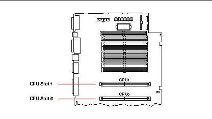
The first CPU module must be installed in the slot labeled CPU0--the one closest to the system's four PCI slots.
If you install two CPU modules, the two must operate at identical clock speeds (300 MHz, for example) and they must have the same size cache memory. This generally means the two CPU modules must have the same part number.
The following figure shows the CPU slot locations on the main logic board.
Figure 5-4
About Peripheral Component Interconnect (PCI) Buses
All system communication with storage peripherals and network interface devices is mediated by a UPA-to-PCI bridge, located on the system's main logic board. This bridge chip manages communication between the UPA bus and the system's two PCI buses. These PCI buses support slots for up to four PCI interface cards. One PCI bus (bus 0) also handles communication between the system and devices connected to the main logic board's SCSI, FastEthernet, serial, parallel, and keyboard/mouse ports.
PCI cards come in a variety of configurations. Not all cards will fit or operate in all PCI slots, so it is important to know the specifications of your PCI cards and the types of cards supported by each PCI slot in the system.
Some PCI cards are as short as 6.875 inches (17.46 cm) in length (called "short" cards), while the maximum length of PCI cards is 12.28 inches (31.19 cm, called "long" cards). Each slot in the system can accommodate either a long or a short card.
Older PCI cards communicate over 32-bit PCI buses, while many newer cards communicate over wider 64-bit buses. All four PCI slots will accept either 32-bit or 64-bit wide cards.
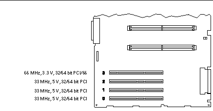
Older PCI cards operate at 5 VDC, while newer cards are designed to operate on 3.3 VDC. Cards that require 5 volts will not operate in 3.3-volt slots, and 3.3-volt cards will not operate in 5-volt slots. "Universal" PCI cards are designed to operate on either 3.3 volts or 5 volts, so these cards can be inserted into either type of slot. The system provides three slots for 5-volt cards and one slot for a 3.3-volt card. All four PCI slots accept universal cards.
Most PCI cards operate at clock speeds of 33 MHz, while some newer cards operate at 66 MHz. All four PCI slots can accept 33-MHz cards. 66-MHz cards are restricted to the slot labelled PCI66-0.
The table below shows the mapping of the PCI slots to the two PCI buses, and the type of PCI cards supported in each slot.
Table 5-1|
Rear Panel Slot Number |
Connector Label |
PCI Bus |
Slot Width (bits)/ Card Type (bits) |
Clock Rates (MHz) |
DC Voltage/ Card Type |
|---|---|---|---|---|---|
|
3 |
PCI66-0 |
1 |
64 / 32 or 64 |
33 and 66 |
3.3 V & Univ |
|
2 |
PCI33-2 |
0 |
64 / 32 or 64 |
33 |
5 V & Univ |
|
1 |
PCI33-1 |
0 |
64 / 32 or 64 |
33 |
5 V & Univ |
|
0 |
PCI33-0 |
0 |
64 / 32 or 64 |
33 |
5 V & Univ |
The following figure shows the PCI slots on the main logic board.
Figure 5-5
Configuration Rules
All slots support PCI universal cards.
All slots support PCI long or short cards.
Each slot can supply up to 16 watts of power. The total power used for all four slots must not exceed 64 watts.
PCI cards may be freely installed in any compatible PCI slots. Slots need not be filled in any particular order. In most cases, the system's I/O performance will be unaffected by placement of PCI cards in the slots. Heavily loaded systems, however, will deliver better overall performance by installing high-throughput interface cards on separate buses. Examples of high-throughput interfaces are dual-channel UltraSCSI host adapters and ATM-622 interfaces.
Overall system availability may also be improved by installing redundant storage or network interfaces on separate PCI buses.
About Internal Disk Drives
Figure 5-6
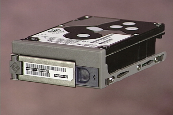
The Enterprise 250 server supports up to six internal, hot-pluggable UltraSCSI disk drives. Drives are 3.5-inches wide and either 1-inch or 1.6-inches high.
All internal drives are supported by the 40-Mbyte per second UltraSCSI interface on the system's main logic board. All drives plug in to a six-disk backplane, which mounts to the rear of the system's disk cage.
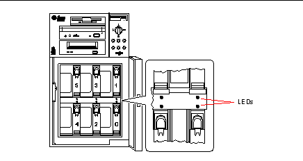
The system's disk cage features six green/yellow LED lights, each one located adjacent to a disk bay. These LEDs indicate the operating status and any fault conditions associated with each disk drive. This diagnostic feature helps the administrator to quickly identify drives requiring service. For additional information about disk drive LEDs, see "Disk LEDs".
The following figure shows the system's six internal disk slots and LEDs. Disk slots are numbered from 0 to 5.
Figure 5-7
The Solstice DiskSuite software supplied with the Solaris server media kit lets you use internal disk drives in a variety of RAID configurations. RAID 0 (striping), RAID 1 (mirroring), RAID 0+1 (striping plus mirroring), and RAID 5 (striping with interleaved parity) are all supported. You can also configure drives as "hot spares." For more information on RAID configurations, see "About Disk Array Configurations and Concepts".
The "hot-plug" feature of the system's internal disk drives allows the removal and installation of drives while the system is operational. This capability significantly reduces system down-time associated with disk drive replacement.
The hot-plug procedure involves software commands for preparing the system prior to removing a disk drive and for reconfiguring the operating environment after installing the replacement drive. The exact hot-plug procedure depends on which version of the Solaris operating environment you are using. For the complete procedure, please refer to Platform Notes: Sun Enterprise 250 Server, available on the Solaris on Sun Hardware AnswerBook. This AnswerBook documentation is provided on the SMCC Supplement CD for the Solaris release you are running.
In order to perform a disk hot-plug procedure, you must know the physical or logical device name for the drive that you want to install or remove. If your system encounters a disk error, often you can find messages about failing or failed disks in your system console. This information is also logged in the /var/adm/messages file(s). These error messages typically refer to a failed disk drive by its physical device name (such as /devices/pci@1f,4000/scsi@3/sd@b,0) or by its logical device name (such as c0t11d0). In addition, some applications may report a disk slot number (0 through 5) or activate an LED located next to the disk drive itself.
You can use the following table to associate a disk slot number with the logical and physical device names for each disk drive.
Table 5-2|
Disk Slot Number |
Logical Device Name |
Physical Device Name |
|---|---|---|
|
Slot 0 |
c0t0d0 |
/devices/pci@1f,4000/scsi@3/sd@0,0 |
|
Slot 1 |
c0t8d0 |
/devices/pci@1f,4000/scsi@3/sd@8,0 |
|
Slot 2 |
c0t9d0 |
/devices/pci@1f,4000/scsi@3/sd@9,0 |
|
Slot 3 |
c0t10d0 |
/devices/pci@1f,4000/scsi@3/sd@a,0 |
|
Slot 4 |
c0t11d0 |
/devices/pci@1f,4000/scsi@3/sd@b,0 |
|
Slot 5 |
c0t12d0 |
/devices/pci@1f,4000/scsi@3/sd@c,0 |
Configuration Rules
Disk drives must be Sun standard 3.5-inch wide UltraSCSI-compatible drives, either 1 inch or 1.6 inches high. UltraSCSI-compatible 1-inch and 1.6-inch high drives can be mixed in the same system.
The SCSI IDs for the disks are hardwired on the disk backplanes. There is no need to set any SCSI ID jumpers on the disk drives themselves. The SCSI target address (SCSI ID) of each disk drive is determined by the slot location where the drive is connected to its UltraSCSI backplane.
The disk drives share the internal SCSI bus with the SCSI removable media devices in the removable media assembly (RMA). The removable media SCSI cable provides the termination for the internal SCSI bus.
For information about implementing RAID configurations, see "About Disk Array Configurations and Concepts".
About Power Supplies
Figure 5-8
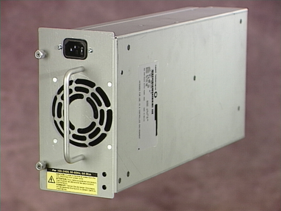
A central power distribution board delivers DC power for all internal system components. The system's power supplies plug in to connectors on this board, and when both supplies are installed, they share equally in satisfying the power demands of the system.
Power supplies are modular units, designed for fast, easy installation or removal, even while the system is fully operational. Supplies are installed in bays at the rear of the system, as shown in the following figure.
Figure 5-9
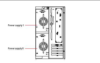
The system can accommodate one or two power supplies. Each supply provides up to 360 watts of DC power. All system configurations can operate with only one power supply installed. A second supply can be used to provide N+1 redundancy, allowing the system to continue operating should one of the power supplies fail.
Power supplies in a redundant configuration feature a "hot swap" capability. You can remove and replace a faulty power supply without turning off the system power or even shutting down the operating system.
Note -
When removing a hot-swappable power supply, do not disengage and reengage the supply in rapid succession. Always remove a supply completely before reinserting the same supply or a replacement supply. Rapid seating and unseating of power supplies may result in false error conditions.
For information about removing and installing power supplies, see "How to Remove a Power Supply" and "How to Install a Power Supply".
Two LED indicators on the rear of the power supply display power status and fault conditions. For additional details, see "Power Supply LEDs".
Note -
Enterprise 250 power supplies will shut down automatically in response to certain over-temperature and power fault conditions (see "Environmental Monitoring and Control"). To recover from an automatic shutdown, you must disconnect the AC power cord, wait roughly 10 seconds, and then reconnect the power cord.
About the Standard Ethernet Port
The system's main logic board provides an auto-sensing, switchable 10BASE-T/100BASE-TX Ethernet interface conforming to the IEEE 802.3u Ethernet standard. The interface configures itself automatically for either 10-Mbps or 100-Mbps operation, depending on network characteristics.
Two rear panel connectors provide access to the Ethernet interface:
-
One RJ-45 connector for connecting a category-5 twisted-pair Ethernet (TPE) cable
-
One Media Independent Interface (MII) connector for connecting an external MII transceiver
Note -
You can use only one of the main logic board Ethernet connectors; you cannot connect to the TPE and MII connectors at the same time.
The Media Independent Interface lets you connect the system to a variety of external 100BASE-TX (Fast) Ethernet transceivers, providing compatibility with different Ethernet wiring types. When an external transceiver is connected to the MII, the system automatically activates the MII port and disables the TPE port.
Sun Microsystems offers an MII-to-AUI transceiver as a separately orderable option (order number X467A). A number of third-party MII transceivers are also available for connecting to TX, T4, FX, and AUI-type Ethernet networks.
For instructions on configuring the main logic board Ethernet interface, see "How to Configure the Standard Ethernet Interface".
For connector diagrams and pin assignments, see "Reference for the Twisted-Pair Ethernet (TPE) Connector" and "Reference for the Media Independent Interface (MII) Ethernet Connector".
For information about operating characteristics and configuration parameters for the hme Fast Ethernet device driver, please see Platform Notes: The hme Fast Ethernet Device Driver. This document is available on Solaris on Sun Hardware AnswerBook, which is provided on the SMCC Supplement CD for the Solaris release you are running.
About the Serial Ports
The system provides two serial communication ports through a pair of DB-25 connectors located on the rear panel. Both ports are capable of synchronous and asynchronous communication. In synchronous mode, each port operates at any rate from 50 Kbaud to 256 Kbaud when the clock is generated internally. When the clock is generated from an external source, synchronous communication occurs at rates up to 384 Kbaud. In asynchronous mode, either port supports baud rates of 50, 75, 110, 200, 300, 600, 1200, 1800, 2400, 4800, 9600, 19200, 38400, 57600, 76800, 115200, 153600, 230400, 307200, and 460800 baud.
Both serial ports can be configured to provide EIA-423 or EIA-232D signal levels. Signal levels are controlled by jumpers located on the system's main logic board. The default setting is EIA-423. For more information about configuring the serial port jumpers, see "About Serial Port Jumpers".
See "Reference for the Serial Port A and B Connectors" for the connector diagram, rear panel icon, and pin assignments.
About the Parallel Port
The system provides one IEEE 1284-compatible, bidirectional parallel port for connecting the system to a local printer or other compatible parallel device. Connectivity is provided by a standard 25-pin DB-25 connector on the rear panel of the system. The parallel port operates at a 2-megabytes per second data transfer rate and supports the EPP protocol modes as well as standard Centronics, Nibble, and Byte modes.
See "Reference for the Parallel Connector" for the connector diagram, rear panel icon, and pin assignments.
About the Main Logic Board Jumpers
The jumpers on the main logic board have the following functions:
-
J2604 and J2605 are used to configure the serial ports for either EIA-423 or EIA-232D operation. For information about the EIA-423/232D jumper settings, see "About Serial Port Jumpers".
-
J2702, J2704, and J2804 are used to affect the operation of the flash PROM located on the main logic board. For information about the flash PROM jumper settings, see "About Flash PROM Jumpers".
The illustration below shows the jumper locations on the main logic board.
Figure 5-10
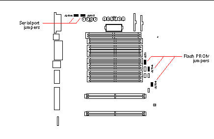
Jumpers are marked on the main logic board with identification numbers. For example, the serial port jumpers are marked J2604 and J2605. Jumper pins are located immediately adjacent to the identification number. Pin 1 is marked with an asterisk (*) in any of the positions shown below.

About Serial Port Jumpers
The serial port jumpers on the main logic board (J2604 and J2605) permit the configuration of the system's two serial ports for either EIA-423 or EIA-232D signal levels. EIA-423 levels are the default standard for North American users. EIA-232D levels are required for digital telecommunication in nations of the European Community.
The figure below shows the jumper locations, and the table describes their function.
Figure 5-11
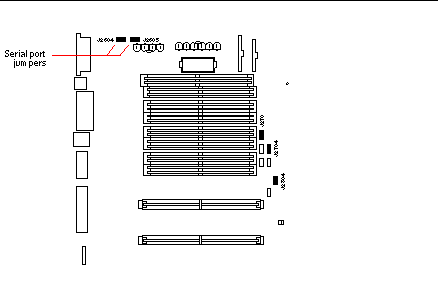 Table 5-3
 |
Jumper |
Shunt on Pins 1 + 2 Selects |
Shunt on Pins 2 + 3 Selects |
Default Shunt on Pins |
|---|---|---|---|
|
J2604 |
EIA-232D |
EIA-423 |
2 + 3 |
|
J2605 |
EIA-232D |
EIA-423 |
2 + 3 |
About Flash PROM Jumpers
The system uses flash PROMs to permit the reprogramming of specific code blocks that are held in non-volatile system memory, and to permit remote reprogramming of that code by an authorized system administrator over a local area network.
Three jumpers on the main logic board affect flash PROM operation. The figure below shows the jumper locations, and the table describes their function.
Figure 5-12
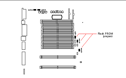 Table 5-4
 |
Jumper |
Shunt on Pins 1 + 2 Selects |
Shunt on Pins 2 + 3 Selects |
Default Shunt on Pins |
|---|---|---|---|
|
J2702 |
Flash PROM |
Not To Be Used |
1 + 2 |
|
J2704 |
Write Protect |
Write Enable |
2 + 3 |
|
J2804 |
High Half Booting |
Normal Booting |
2 + 3 |
Note -
Jumper J2704 is factory-set so that the flash PROM is write-enabled. You use the keyswitch located on the front panel to write protect the flash PROM. When the switch is set to the Locked position, the flash PROM is write-protected. When the switch is set to the Power-on position or to the Diagnostics position, the flash PROM is write-enabled. For descriptions of the various keyswitch settings, see "About the Status and Control Panel".
For descriptions of the various keyswitch settings, see "About the Status and Control Panel".
For more information about flash PROM programming, see the documentation supplied with the flash PROM update CD-ROM.
About the SCSI Removable Media Bays and the External SCSI Port
The removable media assembly located at the top front of the system provides mounting bays for two 5.25-inch, half-height (1.6-inch) SCSI devices. The upper SCSI bay (directly below the diskette drive bay) houses a CD-ROM drive. The lower bay accommodates a second SCSI device, such as an 8-mm tape, a 4-mm DDS-2 or DDS-3 tape, or a quarter-inch cassette tape drive. Both SCSI removable media bays are connected to the same SCSI bus as the internal disk drives. While this bus supports wide SCSI operation for the internal disk drives, the removable media portion of the bus operates in narrow SCSI mode only. The removable media assembly can accommodate wide SCSI (68-pin) devices, however these devices require a 50-to-68-pin adapter cable, and operate in narrow SCSI mode only.
External SCSI devices are supported via a 68-pin SCSI connector located on the system's rear panel. This bus is UltraSCSI-capable (40 Mbytes per second) and can support additional external, single-ended, wide or narrow SCSI devices. The external SCSI bus is separate from the internal SCSI bus for removable media devices and internal disk drives. See "Reference for the SCSI Connector" for a diagram and pinout of the external SCSI connector.
The external SCSI bus will support up to four external SCSI tape devices if the bus is used exclusively for tape devices. When other types of SCSI devices are present on the bus, a maximum of two SCSI tape devices are supported on the external SCSI bus. Additional external tape devices can be supported by installing appropriate PCI host adapter cards.
Target Devices
Up to 15 devices can operate on the external SCSI bus at 20 Mbytes/sec. For UltraSCSI performance of 40 Mbytes/sec, no more than seven devices may be connected. Target addresses for the external SCSI bus (also known as SCSI IDs) are available in a range of 0 through 15. Target address 7 is reserved for the SCSI host adapter located on the main logic board. All devices on the bus must have unique target addresses.
The addresses for the internal CD-ROM and tape drives are determined by jumpers located on the drives. If the CD-ROM and tape drives have been factory-installed, they are configured with the correct addresses for the system.
When installing an internal CD-ROM or tape drive as an option, you should verify the address settings on these devices. The settings usually involve three sets of pins that determine the address in binary. Attaching a jumper across a set of pins creates a binary 1 in that position.
Table 5-5|
0002 = SCSI ID 0 |
0012 = SCSI ID 1 |
0102 = SCSI ID 2 |
|||
|
0112 = SCSI ID 3 |
1002 = SCSI ID 4 |
1012 = SCSI ID 5 |
|||
|
1102 = SCSI ID 6 |
1112 = SCSI ID 7 |
|
|
See the documentation accompanying the drive for device-specific information about checking and setting jumpers.
Bus Length
For UltraSCSI performance on the external SCSI bus, you must adhere to the following bus length restrictions for daisy-chained SCSI devices:
-
For 1 to 3 devices, the maximum bus length is 3 meters (9.84 feet)
-
For 4 to 7 devices, the maximum bus length is 1.5 meters (4.92 feet)
You must include the Enterprise 250 internal bus length (0.5 meter/1.7 feet) in your bus length calculations.
If you exceed these bus length restrictions, UltraSCSI devices may operate at less than 40 Mbytes/sec. Under such conditions, an UltraSCSI device may experience errors that eventually cause it to reset and operate at 20 Mbytes/sec.
For Fast/Wide performance on the external SCSI bus, the maximum SCSI bus length for daisy-chained SCSI devices is 6 meters (19.7 feet), including the Enterprise 250 internal bus length (0.5 meter/1.7 feet).
External SCSI Cabling and Termination
Use the following cabling guidelines to ensure proper device cabling and termination on the external SCSI bus:
-
In order to maintain UltraSCSI performance, all cables used must be UltraSCSI-compliant.
-
The external SCSI bus must be correctly terminated. Most Sun devices use autotermination. See the documentation supplied with the device.
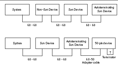
-
If all external mass storage devices use 68-pin connectors, connect all non-Sun devices to the system first and connect a Sun autoterminating device to the end of the chain.
-
If external mass storage devices consist of 68-pin devices and 50-pin devices, connect the Sun 68-pin devices to the system first and terminate the chain with a 50-pin device and its terminator. The 68-pin device connected to the 68-50 pin adapter cable must be autoterminating in order to terminate the high-order bits.
Do not connect 68-pin devices after 50-pin devices; SCSI bus errors will occur.
The following figures provide a summary of the cabling guidelines.
Figure 5-13
Multi-initiator Support
The SCSI implementation of the system includes multi-initiator support: any external host adapter on the bus can drive Termpower. This means that if the system should lose power, the devices on the SCSI bus (except those powered by the system) can continue to operate.
Configuration Rules
For Fast/Wide performance, you can connect up to 15 devices to the external SCSI bus. For UltraSCSI performance, no more than seven devices may be connected. Each device must have a unique target address (SCSI ID) in the range from 0 to 15.
You cannot assign target address 7 to any device; it is reserved for the host adapter on the main logic board.
For UltraSCSI performance on the external SCSI bus, all cables used must be UltraSCSI-compliant, and you must adhere to the following bus length restrictions:
-
For 1 to 3 devices, the maximum bus length is 3 meters (9.84 feet)
-
For 4 to 7 devices, the maximum bus length is 1.5 meters (4.92 feet)
You must include the Enterprise 250 internal bus length (0.5 meter/1.7 feet) in your bus length calculations.
For Fast/Wide performance on the external SCSI bus, the maximum SCSI bus length for daisy-chained SCSI devices is 6 meters (19.7 feet), including the Enterprise 250 internal bus length (0.5 meter/1.7 feet).
UltraSCSI devices can be mixed with non-UltraSCSI devices on the same bus. The UltraSCSI devices will still operate at UltraSCSI speeds (40 Mbytes/sec), provided that the rules for UltraSCSI cabling, bus length, termination, and target devices are followed.
If all external SCSI devices use 68-pin connectors, connect all non-Sun devices to the system first and connect a Sun autoterminating device to the end the chain.
If external mass storage devices consist of 68-pin devices and 50-pin devices, connect the Sun 68-pin devices to the system first and terminate the chain with a 50-pin device and its terminator. The 68-pin device connected to the 68-50 pin adapter cable must be autoterminating in order to terminate the high-order bits.
If you install an internal tape drive in the system, you should assign it target address 4 or 5. If you install an internal CD-ROM in the system, you should assign it target address 6. If these drives have been factory-installed, they are configured with the correct addresses for the system.
The removable media SCSI cable provides the termination for the internal SCSI bus.
- © 2010, Oracle Corporation and/or its affiliates
