How to Install the Main Logic Board
This procedure must be performed by a qualified service-trained maintenance provider. Persons who remove any of the outer panels to access this equipment must observe all safety precautions and comply with skill level requirements, certification, and all applicable local and national laws.
Before You Begin
You must remove all removable components from the old main logic board so that you can transfer them to the replacement board. For more information, see:
Note -
Be sure to remove the NVRAM/TOD module from the old main logic board so that you can transfer it to the replacement board.
Video Demonstration
Figure 6-3

Click on the icon above for a video demonstration.
Click here for Appendix E, Video Player Help.
What to Do
-
Remove the main logic board from its antistatic packaging and place it on an antistatic mat.
Retain the packaging and use it to pack and return the defective board.
-
Set the jumpers on the replacement main logic board so that they are the same as the settings on the old board.
See "About the Main Logic Board Jumpers" for more information about jumper locations and settings.
-
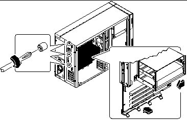
Position the board inside the chassis.
Align the notches at the top and bottom edges of the board with the corresponding tabs on the chassis wall.
Figure 6-4

-
Press the main logic board against the chassis wall as you slide it toward the rear panel.
-
Tighten the three captive screws securing the main logic board to the rear panel.
-
Reconnect the internal cables to the main logic board:
-
Reconnect any external cables to the rear panel of the system.
See "Locating Rear Panel Features".
Note -When the side access panel is removed, the system power interlock switches are activated. This safety mechanism prevents any DC voltages (except 5V standby power) from reaching the main logic board while the side access panel is removed.
What Next
Remove the NVRAM module from the replacement board and install it on the old board for return to Sun Microsystems. See "How to Install the NVRAM/TOD Module".
Complete these tasks to transfer the components that you removed from the old main logic board to the new board:
Complete this task to reassemble the system:
When you are ready to restart the system, be sure to run POST and OpenBoot Diagnostic tests to verify that the system functions correctly with the new parts you have just installed. For additional information, see Chapter 12, Diagnostics and Troubleshooting.
Note -
After installing the new main logic board, you must restore Remote System Control (RSC) configuration parameters before you can use RSC. During RSC configuration, RSC parameters are typically backed up to a hard disk drive. You must restore those parameters to the RSC SEEPROM on the new main logic board. For additional details, see the Remote System Control (RSC) User's Guide.
- © 2010, Oracle Corporation and/or its affiliates
