A P P E N D I X  B

Customer and Field-Replaceable Units

This appendix describes the location customer and field-replacable units within the Sun Fire V215 and V245 Servers.


B.1 Customer and Field-Replaceable Units

FIGURE B-1, FIGURE B-2, and TABLE B-1 illustrates and lists the locations of the customer (CRUs) and field-replaceable units (FRUs) in the Sun Fire V215 and V245 servers.

Figure showing CRUs and FRUs part 1 of 2.

FIGURE B-1 Customer and Field-Replaceable Units, Part 1 of 2


FIGURE B-2 Customer and Field-Replaceable Units, Part 2 of 1
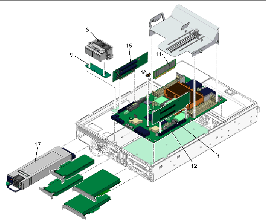

Figure showing CRUs and FRUs part 2 of 2


TABLE B-1 Sun Fire V215 and V245 Servers - CRU and FRU List

Item No.

CRU or FRU Name and Description

Removal Instructions

Installation Instructions

1

Lithium battery

Section 3.3.25, Removing the Battery.

Section 3.3.26, Installing the Battery.

2

Optional DVD super-multi drive

Section 3.3.17, Removing the DVD Super-Multi Drive.

Section 3.3.18, Installing the DVD Super-Multi Drive.

3

Hard drive backplane


The backplane board that contains the Molex connector for interfacing to 2.5 inch SAS or SATA drives.

Section 3.3.19, Removing the Hard Drive Backplane.

Section 3.3.20, Installing the Hard Drive Backplane.

4

Fan tray connector board

Houses the power connectors for the fan assemblies.

Section 3.3.13, Removing the Fan Tray Connector Boards.

Section 3.3.14, Installing the Fan Tray Connector Boards.

5

Fan tray


Fans trays 0, 1, 2, 3, 4, and 5

Section 2.3.1, Removing a Fan Tray.

6

Front I/O board

Section 3.3.15, Removing the Front I/O Board.

Section 3.3.16, Installing the Front I/O Board.

7

Front indicator board

Contains the circuitry and indicators that are displayed on the bezel of the system.

Section 3.3.11, Removing the Front Indicator Board.

Section 3.3.12, Installing the Front Indicator Board.

8

Hard drive fan tray (2)

Section 3.3.21, Removing the Hard Drive Fan Tray.

Section 3.3.22, Installing the Hard Drive Fan Tray.

9

Hard drive fan tray connector board


Driver board for hard drive fan tray, Sun Fire V245 only

Section 3.3.23, (Sun Fire V245) Removing the Hard Drive Fan Tray Connector Board.

Section 3.3.24, (Sun Fire V245) Installing the Hard Drive Fan Tray Connector Board.

10

Hard drives


SAS or SATA hard drives

Section 2.2.1, Removing a Hard Drive.

Section 2.2.2, Installing a Hard Drive.

11

DIMMs


Can be ordered in the following sizes:

  • 512 MB
  • 1 GB
  • 2 GB
  • 4 GB

Section 3.3.5, Removing DIMMs.

Section 3.3.6, Installing DIMMs.

12

Motherboard


The motherboard assembly is a single FRU consisting of one or more UltraSPARCTM IIIi+ CPU processors.

Section 3.3.7, Removing the Motherboard Assembly.

Section 3.3.8, Installing the Motherboard Assembly.

13

Motherboard - front I/O board cable


Interface between the motherboard and the front I/O board

See FIGURE 3-20.


14

Motherboard/SAS backplane cable


Interface cable between the motherboard and the hard drive backplane and the optional DVD super-multi drive

See FIGURE 3-21.


15

PCI-E and
PCI-X riser boards

Section 3.3.3, Removing PCI-E and PCI-X Riser Boards.

Section 3.3.4, Installing PCI-E or PCI-X Riser Boards.

16

Power distribution board (PDB)


Provides a 12 VDC power connection between the power supplies and other boards.

Section 3.3.9, Removing the Power Distribution Board.

Section 3.3.10, Installing the Power Distribution Board.

17

Power supply (PS)


The power supplies provide 3.3 VDC standby power at @ 3 Amps and 12 VDC at 45 Amps.


Section 2.5.1, Removing a Power Supply.

Section 2.5.2, Installing a Power Supply.

18

NVRAM

Section 3.3.27, Removing NVRAM.

Section 3.3.28, Installing NVRAM.