Restarting the System
Note -
As the system starts up, watch for error messages from the POST diagnostic program. If a terminal is not already part of the system, you can install a TTY terminal before continuing the startup. See "Using a Terminal" for terminal settings.
-
The system key switch must be turned to
 (the standby position) (Figure 11-1 or Figure 11-3).
 Caution -
 The outlet must be a 120-240 VAC 30-ampere circuit, intended solely for use by the server cabinet, as described in the site preparation instructions in the Sun Enterprise 6500/5500/4500 Systems Installation Guide. The electrical receptacle must be grounded, and the grounding conductor serving this receptacle must be connected to the earth ground at the service equipment.
-
Enterprise 6500/5500 systems only: turn the Local/Remote switch down, to Local (Figure 11-2).
-
Turn on the AC main power switch (Figure 11-2 or Figure 11-4).
-
Turn on power to the terminal.
A terminal is optional for viewing system messages. For setup instructions, see "Using a Terminal".
-
Turn the front panel key switch to
 (the power on position).
Several things will happen:
-
The left front panel LED (green) turns on immediately to indicate the DC power supply is functioning.
-
The middle front panel LED (yellow) lights immediately and should turn off after approximately 60 seconds.
-
The right front panel LED (green) flashes after POST has ended to show that booting is successful and the operating system is running.
-
The terminal screen lights up upon completion of the internal self-test.
 Caution -
 Never move the server or the expansion cabinets when system power is on. Excessive movement can cause catastrophic disk drive failure. Always power the system OFF before moving cabinets.
-
-
Watch the terminal screen for POST error messages.
At the conclusion of testing, POST automatically configures the system, omitting any devices that have failed diagnostics. After POST ends, the system will boot using the new configuration.
Note -If the middle front panel LED (yellow) remains lit after the system has booted, the system has failed POST.
Note -POST does not test drives or internal parts of SBus cards. To test these devices, run OBP diagnostics manually after the system has booted. Refer to the OpenBoot Command Reference manual for instructions.
-
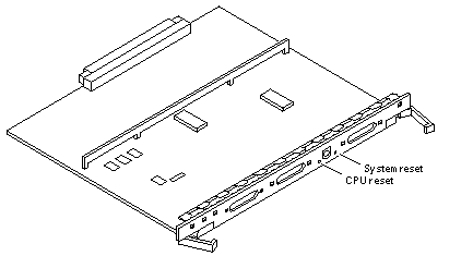
To start POST again, or if the system hangs, press the CPU reset switch on the clock+ board (Figure 11-6).
Figure 11-6 CPU Reset Switch on Clock+ Board

-
If the system displays "not responding" or "no carrier" messages, the Link Integrity Test may be set incorrectly. See "Link Integrity Test" on page 4-19.
- © 2010, Oracle Corporation and/or its affiliates
