CPU/Memory+ Board
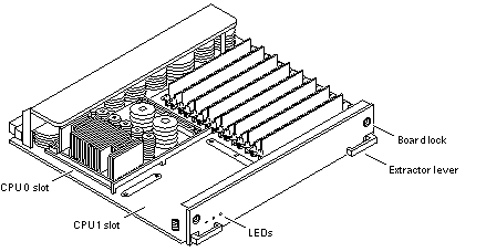
The CPU/Memory+ board (Figure B-5) supports up to 2 CPU modules and 16 SIMMs.
Figure B-5 CPU/Memory+ Board

The CPU/Memory+ board should be installed from the smallest even-numbered slot (0) to the largest even-numbered slot (14). The even-numbered slots are located at the front of the cabinet. When located in these slots, the component side of the board is down. If the front slots are filled, you can use slots at the rear of the cabinet, with the exception of slot 1. Slot 1 requires an I/O+ board because the slot connects to the media tray in the front of the cabinet.
All empty slots must have a filler panel or load board installed.
Note -
The 16-slot Enterprise 6500 card cage requires load boards to reduce the potential for RFI generation. The 8-slot Enterprise 5500 and 4500 card cages use filler panels, which do not have load circuits.
CPU Modules
Each CPU/Memory+ board has two sets of CPU connectors, marked PROC 0 and PROC 1.
The order in which you fill CPU slots is not critical. However, to optimize heat dissipation in the system:
-
Fill all PROC 0 locations on all CPU/Memory+ boards before filling any PROC 1 locations. To receive the maximum quantity of diagnostic information, fill PROC 0 on board 0.
-
After all PROC 0 locations are filled, you may begin filling the PROC 1 locations, again starting from the lowest slot number to the highest.
System Master Board
The board slots are interchangeable. A system master board is selected for the duration of POST and OBP testing, to control the testing processes. The system master is normally the lowest-numbered slot containing a board with a functional CPU. After the tests are finished, the board slots are again fully equivalent.
SIMMs
The CPU/Memory+ board has 16 slots for SIMMs, organized as two banks of eight SIMMs.
Slot Locations
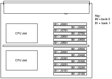
SIMMs must be installed in full banks of eight. Figure B-6 shows the slot numbers for bank 0 and bank 1.
Figure B-6 SIMM Slot Locations

SIMM Selection
The JEDEC standard 3.3 volt SIMMs are available in 8, 32, or 128 Mbyte capacities. All are 168-pin SIMMs.
Do not mix different capacities in a bank.
The Enterprise systems SIMMs operate at 3.3V -- do not substitute other voltage ratings.
- © 2010, Oracle Corporation and/or its affiliates
