Centerplane
Removing the Centerplane
-
Completely power off the Enterprise system.
See the power off instructions in Chapter 11, Powering Off and On .
-
Remove the top bezel.
See Chapter 12, Preparing for Service, for information on removing this assembly.
-
Remove the side vents. Push each side vent backwards until it stops. Then lift the vent off the Enterprise system and set it aside.
-
Remove the top cover.
-
Remove all the boards and power supplies.
See Chapters 3-6 for information on removing the boards and Chapter 7, Power Supplies, for information on removing power supplies.
-
Loosen the bottom three captive screws securing the media tray to the enclosure.
Insert a screwdriver in the notch at the top center of the media tray to pull out the tray and separate it from the rear slip connectors (Figure E-12).
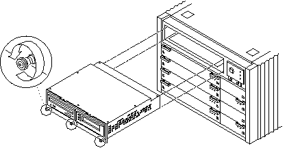
Figure E-17 Removing the media tray

-
Remove the key switch assembly and the 100/240V fan tray assembly.
See "Key Switch Assembly" and "Fan Tray Assembly, 100V/240V" for information on removing these assemblies.
-
Turn over the enclosure and remove the feet on the bottom.
-
Turn the enclosure front side down onto a surface.
-
Remove the 26 screws around the center of the main chassis.
-
Lift and remove the rear chassis and set it aside.
-
Remove the 20 screws that hold the centerplane to the front chassis.
Note -Remember the proper orientation of the centerplane when removing it from the front chassis.
-
Lift the centerplane out and set it aside.
Replacing the Centerplane
-
Place the centerplane in the front chassis.
Be sure the centerplane has the proper orientation when placed in the front chassis.
-
Replace the 20 screws that hold the centerplane to the front chassis.
-
Place the rear chassis on the front chassis.
-
Replace the 26 screws around the center of the main chassis.
-
Replace the feet on the bottom of the enclosure.
Screw in one foot in each corner.
-
Turn the enclosure over so that the feet are supporting the chassis.
-
Replace all boards and power supplies.
See Chapters 3-6 for information on replacing the boards and Chapter 7, Power Supplies, for information on replacing power supplies.
-
Replace the media tray.
Tighten the bottom three captive screws and secure the media tray to the enclosure (Figure E-12).
-
Replace the key switch assembly and the 100/240V fan tray assembly.
See "Key Switch Assembly" and "Fan Tray Assembly, 100V/240V" for information on replacing these assemblies.
-
Replace the top cover.
-
Replace the side vents. Place each vent alongside the main chassis and push the vent forward until it stops.
-
Replace the top bezel.
See Chapter 12, Preparing for Service, for information on replacing this assembly.
-
Power on the Enterprise system.
See the power on instructions in Chapter 11, Powering Off and On .
- © 2010, Oracle Corporation and/or its affiliates
