| Sun Fire V890 Server Service Manual |
| Sun Fire V890 Server Service Manual |
| A P P E N D I X B |
|
System LEDs |
This appendix gives you reference information about the LEDs on the Sun Fire V890 server. Topics covered in this appendix include:
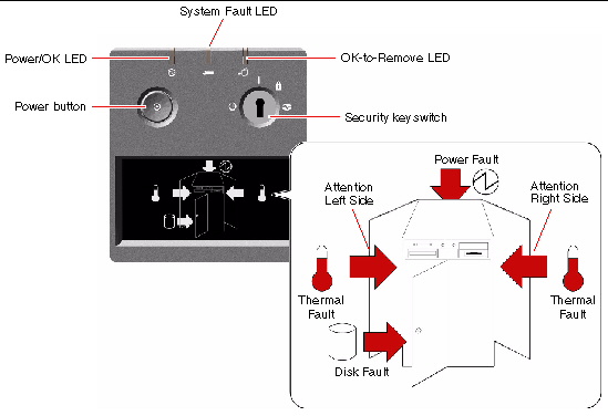
The system status and control panel includes several LED status indicators, a Power button, and a security keyswitch. The following figure shows the status and control panel.
Several LED status indicators provide general system status, alert you to system problems, and help you to determine the location of system faults.
The general status LEDs work in conjunction with the specific fault LED icons. For example, a fault in the disk subsystem illuminates both the system Fault LED at the top of the panel and the Disk Fault icon in the graphical display below it. Fault LEDs within the enclosure help pinpoint the location of the faulty device. Since all front panel status LEDs are powered by the system's 5-volt standby power source, fault LEDs remain lit for any fault condition that results in a system shutdown.
During system startup, the front panel LEDs are individually toggled on and off to verify that each one is working correctly. After that, the front panel LEDs operate as described in the following table.
|
|
||
|
|
This amber LED lights to indicate a serious system fault. When this LED is lit, one or more icons in the display panel may also light to indicate the specific nature and location of the fault. |
|
|
|
This amber LED lights to indicate that an internal
|
|
|
|
This amber LED lights to indicate a serious disk subsystem fault that is likely to bring down the system. When this LED is lit, one or more disk LEDs may also be lit at the front of the disk cage, indicating the source of the fault. See About Disk Drive LEDs. |
|
|
|
This amber LED lights to indicate a serious power subsystem fault that is likely to bring down the system. When this LED is lit, one or more power supply LEDs may also be lit on the system rear panel. See About Power Supply LEDs. |
|
|
|
This amber LED lights to indicate a serious thermal fault (fan fault or overtemperature condition) that is likely to bring down the system. There are two Thermal Fault LEDs in the display to indicate whether the fault is located on the left or right side of the system. In the event of a fan fault, a fault LED inside the system will indicate the faulty fan assembly. See About Fan Tray LEDs. |
|
|
|
This amber LED lights to indicate that an internal component on the left side of the system requires servicing. |
|
|
|
This amber LED lights to indicate that an internal component on the right side of the system requires servicing. |
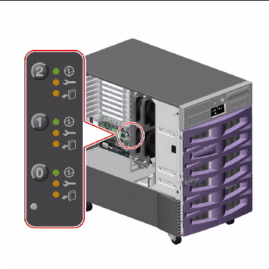
The CPU/Memory slot LEDs are located on the horizontal panel between CPU/Memory slots B and C and are visible when the right side door is open. There are two LEDs for each CPU/Memory slot, as shown below.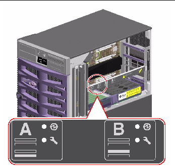
|
|
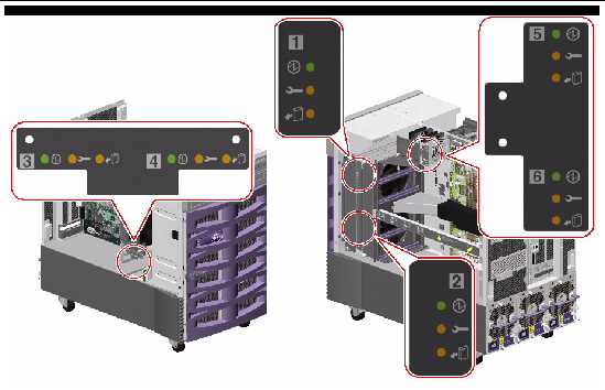
The PCI slot LEDs are located on the vertical bracket on the right side of the PCI slots and are visible when the left side door is open. There are three LEDs for each PCI slot, as shown below.
|
|
||
|
|
Blinks while the card is being tested, when a hot-plug operation is in progress, or when the card is powered on but logically detached from the operating system. |
|
|
|
The following table shows how to interpret the various possible LED patterns.
|
Note - If the slot is empty and the Fault or OK-to-Remove LED is on, pressing the contact push button for the slot will clear the LED. |
For more information about PCI cards and hot-plug operations, see:
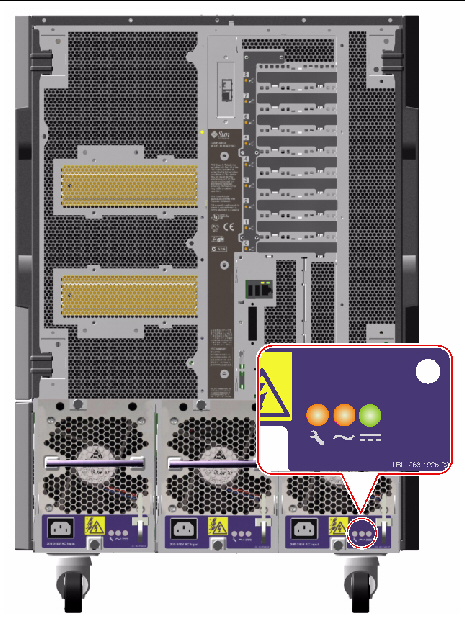
There are three LEDs located on the rear of each power supply, as shown below.
|
|
||
|
|
Lights when AC power input is present and within acceptable operating limits. |
|
|
|
Lights when all DC outputs are functional and within acceptable operating limits. |
The Thermal Fault LED on the system status and control panel indicates the overall status of the cooling system. The Thermal Fault LED lights when a fan fault or overtemperature condition is detected. LEDs inside the system indicate the fault status of each fan tray assembly.
The fan tray LEDs are located beside or beneath each fan tray assembly. There are three LEDs per fan tray, as shown below.
|
|
||
|
|
||
|
|
Lights when it is safe to remove the fan tray assembly from a powered-on system (only when redundant fan trays are present). |
The following table shows how to interpret the various possible LED patterns.
|
|
|
|
|
|---|---|---|---|
|
The fan tray is not receiving power or is improperly inserted. |
|||
|
The fan tray has encountered a fault and can be safely removed from a powered-on system. |
For more information about fan trays and hot-plug operations, see:
The Disk Fault LED on the system status and control panel indicates the general status of the disk subsystem. The Disk Fault LED lights when a fault is detected in the disk subsystem. LEDs inside the system indicate the fault status of individual disk drives.
There are three LEDs for each disk drive. The disk drive LEDs are located on the front of the disk cage, as shown below.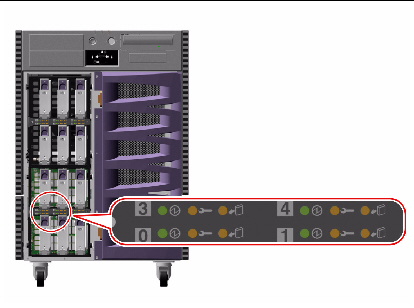
The following table shows how to interpret the various possible LED patterns.
For more information about disk drives, refer to the Sun Fire V890 Server Owner's Guide. For more information about hot-plug operations, see About Hot-Pluggable and Hot-Swappable Components.
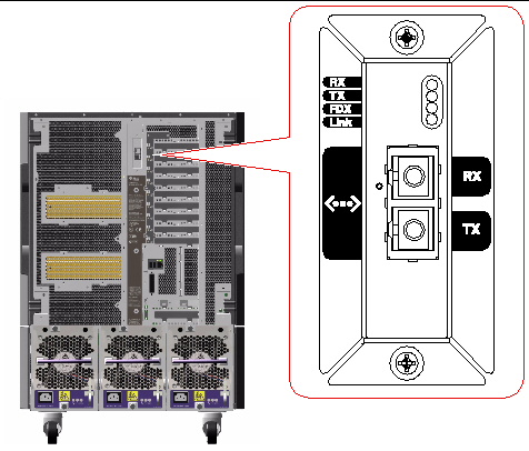
Four LEDs provide status information for the Gigabit Ethernet port. The LEDs are located above the Gigabit Ethernet port on the system rear panel, as shown below.
|
Indicates that the Gigabit Ethernet interface is operating in full-duplex mode. |
||
| Sun Fire V890 Server Service Manual | 817-3957-12 |
Copyright © 2005, Sun Microsystems, Inc. All Rights Reserved.