| Netra CT Server Service Manual
|
   
|
This appendix gives the connector pinouts for the following Netra CT server cards:
A.1 CPU Card
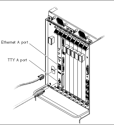
FIGURE A-1 shows the locations of the connectors on the CPU card.
FIGURE A-1 Connectors on the CPU Card
A.1.1 Ethernet A Port
The twisted pair Ethernet connector is an R-J45 connector. The controller auto-negotiates to either 10BASE-T or 100 BASE-T.
FIGURE A-2 RJ-45 Ethernet Connector Diagram

TABLE A-1 Ethernet Connector Pinouts, CPU Card (J2301)
|
Pin No.
|
Description
|
|
1
|
TXD+
|
|
2
|
TXD-
|
|
3
|
RXD+
|
|
4
|
4T_D3P
|
|
5
|
4T_D3P
|
|
6
|
RXD-
|
|
7
|
4T_D4P
|
|
8
|
4T_D4P
|
A.1.2 TTY A Port
This port is connected logically to serial port A. It is intended to be used only for serial output to a terminal.

|
Caution - Serial port A is also connected through the rear cPCI connectors. No mechanism is provided to disable simultaneous input from the front panel and the rear cPCI connectors. Attempts to input data from both ports will place the board in an unknown state.
|
FIGURE A-3 TTY A Connector

TABLE A-2 shows the TTY A connector pinouts.
TABLE A-2 TTY A Connector Pinouts
|
Pin
|
Signal Name
|
|
Pin
|
Signal Name
|
|
1
|
FP_SER_A_DTR
|
|
5
|
FP_SER_A_RXD
|
|
2
|
FP_SER_A_CTS
|
|
6
|
FP_SER_A_RTS
|
|
3
|
FP_SER_A_TXD
|
|
7
|
FP_SER_A_DCD
|
|
4
|
FP_SER_A_GND
|
|
8
|
Shield GND
|
A.2 CPU Front Transition Card, Netra CT 410 Server
FIGURE A-4 shows the locations of the connectors on the CPU front transition card (CPU FTC) for the Netra CT 410 server.
FIGURE A-4 Connectors on the CPU Front Transition Card (Netra CT 410 Server)

A.2.1 SCSI (VHDC)
The SCSI port on the CPU FTC for the Netra CT 410 server is a 68-pin CHAMP very high-density connector (VHDC). A VHDC-to-SCSI 3 cable is available through Sun, if necessary (part number 530-2453-xx, X3832A).
TABLE A-3 SCSI Port Pinouts, CPU FTC for the Netra CT 410 Server
|
Pin No.
|
Signal
|
|
Pin No.
|
Signal
|
|
Pin No.
|
Signal
|
|
1
|
GND
|
|
24
|
GND
|
|
47
|
DATA 7
|
|
2
|
PRES_L
|
|
25
|
GND
|
|
48
|
PL_L
|
|
3
|
GND
|
|
26
|
GND
|
|
49
|
PRES_L
|
|
4
|
GND
|
|
27
|
GND
|
|
50
|
GND
|
|
5
|
GND
|
|
28
|
GND
|
|
51
|
TERM PWR
|
|
6
|
GND
|
|
29
|
GND
|
|
52
|
TERM PWR
|
|
7
|
GND
|
|
30
|
GND
|
|
53
|
GND
|
|
8
|
GND
|
|
31
|
GND
|
|
54
|
GND
|
|
9
|
GND
|
|
32
|
GND
|
|
55
|
ATN_L
|
|
10
|
GND
|
|
33
|
GND
|
|
56
|
GND
|
|
11
|
GND
|
|
34
|
GND
|
|
57
|
BSY_L
|
|
12
|
GND
|
|
35
|
DATA 12
|
|
58
|
ACK_L
|
|
13
|
GND
|
|
36
|
DATA 13
|
|
59
|
RST_L
|
|
14
|
GND
|
|
37
|
DATA 14
|
|
60
|
MSG_L
|
|
15
|
GND
|
|
38
|
DATA 15
|
|
61
|
SEL_L
|
|
16
|
GND
|
|
39
|
PH_L
|
|
62
|
CD_L
|
|
17
|
TERM PWR
|
|
40
|
DATA 0
|
|
63
|
REQ_L
|
|
18
|
TERM PWR
|
|
41
|
DATA 1
|
|
64
|
IO_L
|
|
19
|
GND
|
|
42
|
DATA 2
|
|
65
|
DATA 8
|
|
20
|
GND
|
|
43
|
DATA 3
|
|
66
|
DATA 9
|
|
21
|
GND
|
|
44
|
DATA 4
|
|
67
|
DATA 10
|
|
22
|
GND
|
|
45
|
DATA 5
|
|
68
|
DATA 11
|
|
23
|
GND
|
|
46
|
DATA 6
|
|
|
|
A.2.2 Parallel Port
The parallel port on the CPU FTC for the Netra CT 410 server is an AMPLIMITE SLIMLINE female receptacle.
FIGURE A-5 Parallel Connector

TABLE A-4 Parallel Port Pinouts, CPU FTC for the Netra CT 410 Server
|
Pin No.
|
Signal
|
|
Pin No.
|
Signal
|
|
1
|
STB
|
|
14
|
AFD
|
|
2
|
PD0
|
|
15
|
ERR
|
|
3
|
PD1
|
|
16
|
INIT
|
|
4
|
PD2
|
|
17
|
SLIN
|
|
5
|
PD3
|
|
18
|
DGND
|
|
6
|
PD4
|
|
19
|
DGND
|
|
7
|
PD5
|
|
20
|
DGND
|
|
8
|
PD6
|
|
21
|
DGND
|
|
9
|
PD7
|
|
22
|
DGND
|
|
10
|
ACK
|
|
23
|
DGND
|
|
11
|
BUSY
|
|
24
|
DGND
|
|
12
|
PE
|
|
25
|
DGND
|
|
13
|
SLCT
|
|
26
|
DGND
|
A.2.3 Ethernet B Port
The Ethernet B port on the CPU FTC for the Netra CT 410 server is an RJ-45 connector for 10/100.
FIGURE A-6 RJ-45 Ethernet Connector Diagram

TABLE A-5 Ethernet B Connector Pinouts, CPU FTC for the Netra CT 410 Server
|
Pin No.
|
Description
|
|
1
|
TXD+
|
|
2
|
TXD-
|
|
3
|
RXD+
|
|
4
|
Not used
|
|
5
|
Not used
|
|
6
|
RXD-
|
|
7
|
Not used
|
|
8
|
Not used
|
A.2.4 TTY B
The TTY B port on the CPU FTC for the Netra CT 410 server is a DB-9 male connector.
FIGURE A-7 TTY B Connector

TABLE A-6 TTY B Port Pinouts, CPU FTC for the Netra CT 410 Server
|
Pin No.
|
Signal Name
|
|
1
|
DCD
|
|
2
|
RXD
|
|
3
|
TXD
|
|
4
|
DTR
|
|
5
|
GND
|
|
6
|
DSR
|
|
7
|
RTS
|
|
8
|
CTS
|
|
9
|
RI
|
A.3 CPU Rear Transition Card
FIGURE A-8 shows the locations of the connectors on the CPU rear transition card (CPU RTC). The CPU rear transition card is the same for both the Netra CT 810 server and the Netra CT 410 server; only the location in the rear card cage differs.
FIGURE A-8 Connectors on the CPU Rear Transition Card

A.3.1 SCSI (VHDC)
The SCSI port on the CPU RTC is a 68-pin CHAMP very high-density connector (VHDC). A VHDC-to-SCSI 3 cable is available through Sun, if necessary (part number 530-2453-xx, X3832A).
TABLE A-7 SCSI Port Pinouts, CPU RTC
|
Pin No.
|
Signal
|
|
Pin No.
|
Signal
|
|
Pin No.
|
Signal
|
|
1
|
GND
|
|
24
|
GND
|
|
47
|
DATA 7
|
|
2
|
PRES_L
|
|
25
|
GND
|
|
48
|
PL_L
|
|
3
|
GND
|
|
26
|
GND
|
|
49
|
PRES_L
|
|
4
|
GND
|
|
27
|
GND
|
|
50
|
GND
|
|
5
|
GND
|
|
28
|
GND
|
|
51
|
TERM PWR
|
|
6
|
GND
|
|
29
|
GND
|
|
52
|
TERM PWR
|
|
7
|
GND
|
|
30
|
GND
|
|
53
|
GND
|
|
8
|
GND
|
|
31
|
GND
|
|
54
|
GND
|
|
9
|
GND
|
|
32
|
GND
|
|
55
|
ATN_L
|
|
10
|
GND
|
|
33
|
GND
|
|
56
|
GND
|
|
11
|
GND
|
|
34
|
GND
|
|
57
|
BSY_L
|
|
12
|
GND
|
|
35
|
DATA 12
|
|
58
|
ACK_L
|
|
13
|
GND
|
|
36
|
DATA 13
|
|
59
|
RST_L
|
|
14
|
GND
|
|
37
|
DATA 14
|
|
60
|
MSG_L
|
|
15
|
GND
|
|
38
|
DATA 15
|
|
61
|
DEL_L
|
|
16
|
GND
|
|
39
|
PH_L
|
|
62
|
CD_L
|
|
17
|
TERM PWR
|
|
40
|
DATA 0
|
|
63
|
REQ_L
|
|
18
|
TERM PWR
|
|
41
|
DATA 1
|
|
64
|
IO_L
|
|
19
|
GND
|
|
42
|
DATA 2
|
|
65
|
DATA 8
|
|
20
|
GND
|
|
43
|
DATA 3
|
|
66
|
DATA 9
|
|
21
|
GND
|
|
44
|
DATA 4
|
|
67
|
DATA 10
|
|
22
|
GND
|
|
45
|
DATA 5
|
|
68
|
DATA 11
|
|
23
|
GND
|
|
46
|
DATA 6
|
|
|
|
A.3.2 TTY A and B Ports
The TTY A and B ports are stacked mini 9-pin connectors. The signal interface of the connector is as follows:
|
TTY A of Dual Connector
|
|
TTY B of Dual Connector
|
|
Pin
|
Signal
|
|
Pin
|
Signal
|
|
P1A
|
DCDA
|
|
P1B
|
DCDB
|
|
P2A
|
RXDA
|
|
P2B
|
RXDB
|
|
P3A
|
TXDA
|
|
P3B
|
TXDB
|
|
P4A
|
DTRA
|
|
P4B
|
DTRB
|
|
P5A
|
DGNDA
|
|
P5B
|
DGNDB
|
|
P6A
|
DSRA
|
|
P6B
|
DSRB
|
|
P7A
|
RTSA
|
|
P7B
|
RTSB
|
|
P8A
|
CTSA
|
|
P8B
|
CTSB
|
|
P9A
|
RIA
|
|
P9B
|
RIB
|
|
Note - The two TTY ports require the use of specific adapter cables. Use the Serial Cable Adapter, MDSM-9F to DB9M, (6 inch 9 wires), P/N C-CEL-10110-10. The manufacturer is Computer Cable Makers Inc. and can be ordered directly through them.
|
A.3.3 Ethernet A and B Ports
The Ethernet A and B ports on the CPU RTC are RJ-45 connectors for 10/100.
FIGURE A-9 RJ-45 Ethernet Connector Diagram
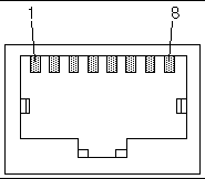
TABLE A-8 Ethernet A and B Connector Pinouts, CPU RTC
|
Pin No.
|
Description
|
|
1
|
TXD+
|
|
2
|
TXD-
|
|
3
|
RXD+
|
|
4
|
Not used
|
|
5
|
Not used
|
|
6
|
RXD-
|
|
7
|
Not used
|
|
8
|
Not used
|
A.3.4 PIM Card Interface
The host CPU rear transition card supports a PMC I/O module (PIM). A PIM is generally located on a transition card to enable rear I/O from the CompactPCI bus chassis. Custom PIMs provide additional I/Os that do not fit on the standard transition card rear panel. (For more information on PIM slot mechanics, electrical and logical information, see VITA 36 - PMC I/O Module Standard available http://www.vita.com and the IEEE P1386 Standard). The single-sized PIM measures 2.92 inches (74 mm) wide and 2.72 inches (69 mm) deep.
The PIM card must be mounted on the host CPU rear transition card before the rear transition card is inserted in a Netra CT server.

|
Caution - A PIM card must be used with its matching PMC. Any other combination could lead to damage of the PIM or PMC.
|
A.4 Alarm Card, 6U Single-Wide
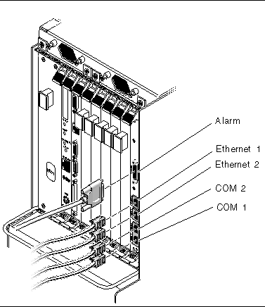
FIGURE A-10 shows the locations of the connectors on the 6U single-wide alarm card. Note that the figure shows the 6U single-wide alarm card installed in a Netra CT 810 server; the 6U single-wide alarm card will be installed in a different slot in a Netra CT 410 server, but the ports are exactly the same.
FIGURE A-10 Connector Ports in the 6U Single-Wide Alarm Card
A.4.1 Alarm Port
I/O connections are available through the male DB-15 alarm port.
FIGURE A-11 Alarm Port

TABLE A-9 Alarm Port Pinouts
|
Pin No.
|
Signal
|
Pin No.
|
Signal
|
Pin No.
|
Signal
|
|
1
|
RESET0 +
|
6
|
ALARM0_NC
|
11
|
ALARM2_NO
|
|
2
|
RESET0 -
|
7
|
ALARM0_COM
|
12
|
ALARM2_NC
|
|
3
|
RESET1 +
|
8
|
ALARM1_NO
|
13
|
ALARM2_COM
|
|
4
|
RESET1 -
|
9
|
ALARM1_NC
|
14
|
ALARM3_NO
|
|
5
|
ALARM0_NO
|
10
|
ALARM1_COM
|
15
|
ALARM3_COM
|
A.4.2 Ethernet Ports 1 and 2
Ethernet ports 1 and 2 on the alarm cards use standard RJ-45 connectors. Ethernet port 1 is a 10Mbps Ethernet port, and Ethernet port 2 is a 10/100 Mbps Ethernet port.
FIGURE A-12 RJ-45 Ethernet Connector Diagram

TABLE A-10 Ethernet Ports 1 and 2 Pinouts
|
Pin No.
|
Description
|
Pin No.
|
Description
|
|
1
|
TX+
|
5
|
Not used
|
|
2
|
TX-
|
6
|
RX-
|
|
3
|
RX+
|
7
|
Not used
|
|
4
|
Not used
|
8
|
Not used
|
A.4.3 COM Ports 1 and 2
COM ports 1 and 2 on the alarm cards use standard RJ-45 connectors.
FIGURE A-13 RJ-45 Ethernet Connector Diagram

TABLE A-11 COM Port 1 Pinouts
|
Pin No.
|
Description
|
Pin No.
|
Description
|
|
1
|
RTS1
|
5
|
DCD1
|
|
2
|
DTR1
|
6
|
RXD1
|
|
3
|
TXD1
|
7
|
DSR1
|
|
4
|
GND
|
8
|
CTS1
|
TABLE A-12 COM Port 2 Pinouts
|
Pin No.
|
Description
|
Pin No.
|
Description
|
|
1
|
RTS2
|
5
|
DCD2
|
|
2
|
DTR2
|
6
|
RXD2
|
|
3
|
TXD2
|
7
|
DSR2
|
|
4
|
GND
|
8
|
CTS2
|
A.5 Alarm Card, 3U Double-Wide
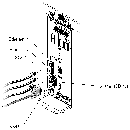
FIGURE A-14 shows the locations of the connectors on the 3U double-wide alarm card for the Netra CT 410 server.
FIGURE A-14 Connectors on the Alarm Card (Netra CT 410 Server)
A.5.1 Ethernet Ports 1 and 2
Ethernet ports 1 and 2 on the alarm cards use standard RJ-45 connectors. Ethernet port 1 is a 10Mbps Ethernet port, and Ethernet port 2 is a 10/100 Mbps Ethernet port.
FIGURE A-15 RJ-45 Ethernet Connector Diagram

TABLE A-13 Ethernet Ports 1 and 2 Pinouts
|
Pin No.
|
Description
|
Pin No.
|
Description
|
|
1
|
TX+
|
5
|
Not used
|
|
2
|
TX-
|
6
|
RX-
|
|
3
|
RX+
|
7
|
Not used
|
|
4
|
Not used
|
8
|
Not used
|
A.5.2 COM Ports 1 and 2
COM ports 1 and 2 on the alarm cards use standard RJ-45 connectors.
FIGURE A-16 RJ-45 Ethernet Connector Diagram

TABLE A-14 COM Port 1 Pinouts
|
Pin No.
|
Description
|
Pin No.
|
Description
|
|
1
|
RTS1
|
5
|
DCD1
|
|
2
|
DTR1
|
6
|
RXD1
|
|
3
|
TXD1
|
7
|
DSR1
|
|
4
|
GND
|
8
|
CTS1
|
TABLE A-15 COM Port 2 Pinouts
|
Pin No.
|
Description
|
Pin No.
|
Description
|
|
1
|
RTS2
|
5
|
DCD2
|
|
2
|
DTR2
|
6
|
RXD2
|
|
3
|
TXD2
|
7
|
DSR2
|
|
4
|
GND
|
8
|
CTS2
|
A.5.3 Alarm Port
I/O connections are available through the male DB-15 alarm port.
FIGURE A-17 Alarm Port

TABLE A-16 Alarm Port Pinouts
|
Pin No.
|
Signal
|
Pin No.
|
Signal
|
Pin No.
|
Signal
|
|
1
|
RESET0 +
|
6
|
ALARM0_NC
|
11
|
ALARM2_NO
|
|
2
|
RESET0 -
|
7
|
ALARM0_COM
|
12
|
ALARM2_NC
|
|
3
|
RESET1 +
|
8
|
ALARM1_NO
|
13
|
ALARM2_COM
|
|
4
|
RESET1 -
|
9
|
ALARM1_NC
|
14
|
ALARM3_NO
|
|
5
|
ALARM0_NO
|
10
|
ALARM1_COM
|
15
|
ALARM3_COM
|
A.6 Alarm Rear Transition Card
FIGURE A-10 shows the locations of the connectors on the alarm rear transition card (alarm RTC).
FIGURE A-18 Connectors on the Alarm Rear Transition Card

A.6.1 Ethernet Ports 1 and 2
Ethernet ports 1 and 2 on the alarm rear transition card use standard RJ-45 connectors. Ethernet port 1 is a 10Mbps Ethernet port, and Ethernet port 2 is a 10/100 Mbps Ethernet port.
FIGURE A-19 RJ-45 Ethernet Connector Diagram
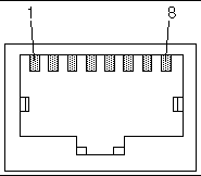
TABLE A-17 Ethernet Ports 1 and 2 Pinouts
|
Pin No.
|
Description
|
Pin No.
|
Description
|
|
1
|
TX+
|
5
|
Not used
|
|
2
|
TX-
|
6
|
RX-
|
|
3
|
RX+
|
7
|
Not used
|
|
4
|
Not used
|
8
|
Not used
|
A.6.2 COM Ports 1 and 2
COM ports 1 and 2 on the alarm rear transition card use standard DB-9 male connectors.
FIGURE A-20 COM Ports 1 and 2

TABLE A-18 COM Ports 1 and 2 Connector Pinouts, Alarm Rear Transition Card
|
Pin No.
|
Description
|
|
1
|
DCD
|
|
2
|
RXD
|
|
3
|
TXD
|
|
4
|
DTR
|
|
5
|
GND
|
|
6
|
DSR
|
|
7
|
RTS
|
|
8
|
CTS
|
|
9
|
RI
|
A.6.3 Alarm Port
The alarm port on the alarm rear transition card uses a standard male DB-15 connector.
FIGURE A-21 Alarm Port

TABLE A-19 Alarm Port Pinouts
|
Pin No.
|
Signal
|
Pin No.
|
Signal
|
Pin No.
|
Signal
|
|
1
|
RESET0 +
|
6
|
ALARM0_NC
|
11
|
ALARM2_NO
|
|
2
|
RESET0 -
|
7
|
ALARM0_COM
|
12
|
ALARM2_NC
|
|
3
|
RESET1 +
|
8
|
ALARM1_NO
|
13
|
ALARM2_COM
|
|
4
|
RESET1 -
|
9
|
ALARM1_NC
|
14
|
ALARM3_NO
|
|
5
|
ALARM0_NO
|
10
|
ALARM1_COM
|
15
|
ALARM3_COM
|
| Netra CT Server Service Manual
|
816-2482-11
|
   
|
Copyright © 2003, Sun Microsystems, Inc. All rights reserved.


