C H A P T E R  2

Netra CT System Equipment Models

This chapter provides illustrations of the Netra CT system equipment models, and contains the following sections:


Modeling a Netra CT System

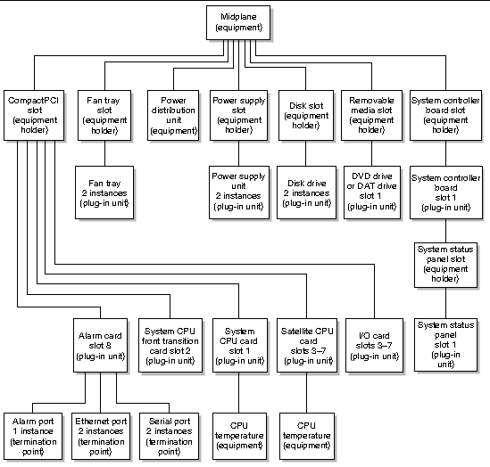
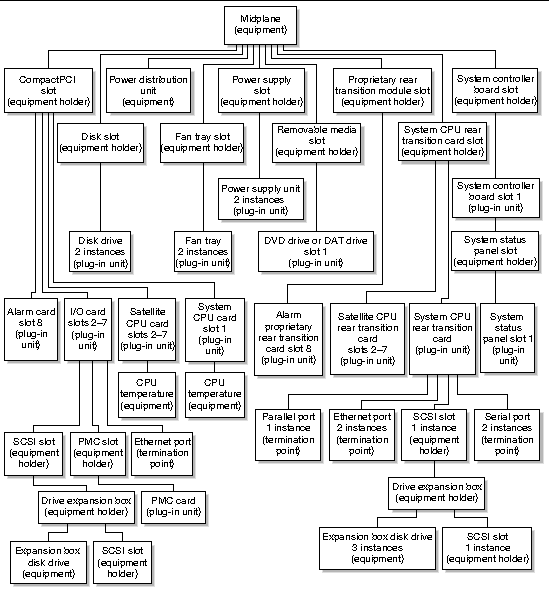
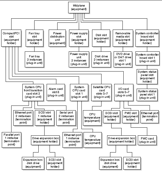
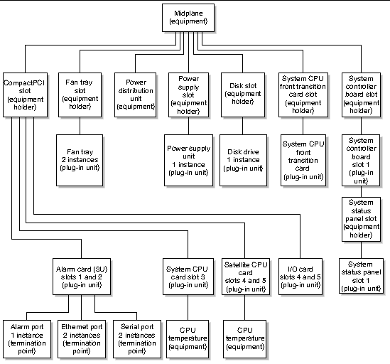
Equipment models show how the Netra CT element management agent software views the Netra CT system hardware. Each equipment model presents a Netra CT system in a containment hierarchy of hardware components, with the midplane at the root of the hierarchy. For example, a cPCI slot might contain an alarm card, which in turn will contain a number of Ethernet and serial ports. These relationships extending from the midplane form a hierarchy of hardware resources. This hierarchy is modeled using relationships between managed objects representing the hardware resources.
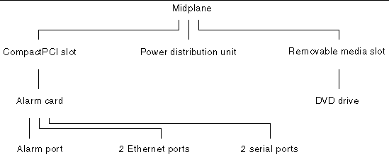
  FIGURE 2-1 Partial Hardware Resource Hierarchy

Diagram showing an example hierarchy of hardware resources.

Managed Objects

In the Netra CT software, a managed resource is represented as a managed object, which presents information needed to manage the resource. A managed resource can be represented by a single managed object, or by several managed objects. An agent typically contains or provides views of many managed objects.

FIGURE 2-2 shows the class names of the hardware Netra CT software managed objects, and TABLE 2-1 provides definitions for these objects.
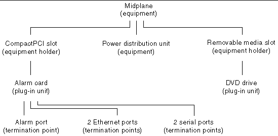
  FIGURE 2-2 Hardware Resource Hierarchy Showing Managed Object Classes

Diagram showing managed object class names superimposed on the hardware resource hierarchy displayed in FIGURE 2-1.


TABLE 2-1 Managed Object Class Definitions

Managed Object Class

Definition

Network element

Network elements can be standalone devices or multi-component, geographically distributed systems.

Equipment holder

Represents physical resources of the network element that are capable of holding other physical resources. For example, CompactPCI slots, fan tray slots, and system controller board slots are equipment holder resources.

Plug-in unit

This managed entity represents equipment that can be physically inserted or removed from slots of the system (for example, CompactPCI I/O cards and power supply units).

Equipment

Equipment represents those externally manageable physical components which are not FRUs (for example, a power distribution unit or a CPU temperature sensor) of a network that are not modeled as a plug-in unit or an equipment holder.

Termination point

Represents the points where physical paths terminate (for example, Ethernet and serial ports) and physical path functions.


Viewing the Equipment Model Hierarchies

Both the SNMP interface and the JMX compatible Netra CT element management API provide ways to traverse the equipment containment hierarchy. You can view the managed objects of a Netra CT system through the system's alarm card or through the host CPU board. You can also view the managed objects from the agent on any satellite CPU board. In both system-wide views, the system's midplane is at the top of the equipment hierarchy and all other hardware objects (slots, fan trays, I/O cards, and so on) are displayed subordinate to the midplane.

When viewing the system through the alarm card (defined as the system view from the alarm card), the alarm card's termination points (alarm port, Ethernet ports, and serial ports) are displayed in the model, but the host CPU board's termination points are not displayed.

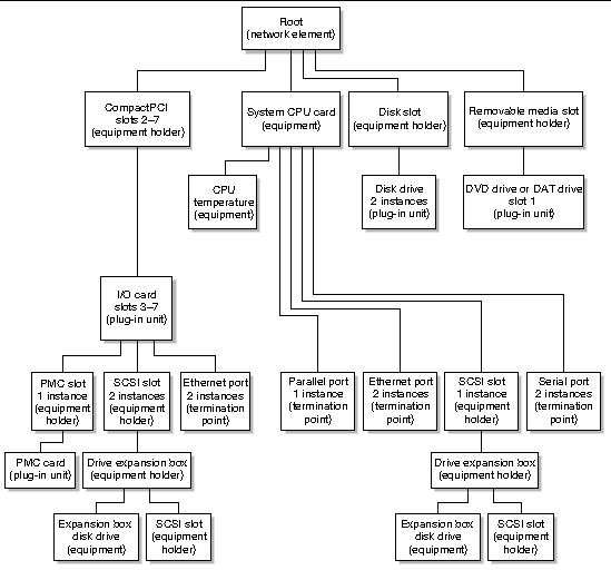
Conversely, when you view the system through the host CPU board (the system view from host CPU board), the alarm card's termination points are not displayed, but the host CPU board's termination points, and any hardware connected to the host CPU board (for example, SCSI devices), is displayed.

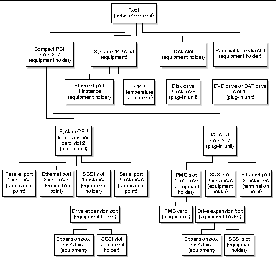
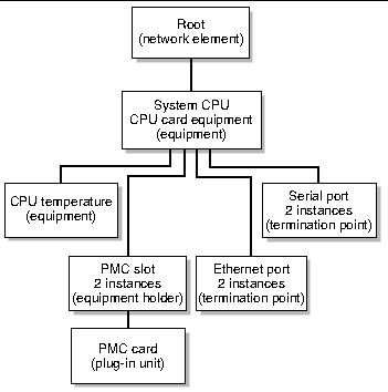
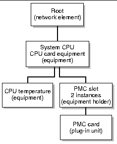
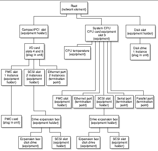
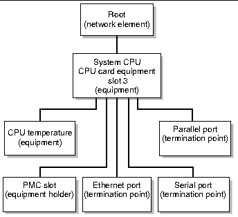
You can also view the equipment model with the host CPU board or a supported satellite CPU board as the network element at the top of the hierarchy. In these models (defined as the host CPU board local view and satellite CPU board local view), only the objects directly controlled by the host or satellite CPU board are displayed. Other objects, like the midplane, alarm card, and the power distribution unit, are not seen in these equipment models.

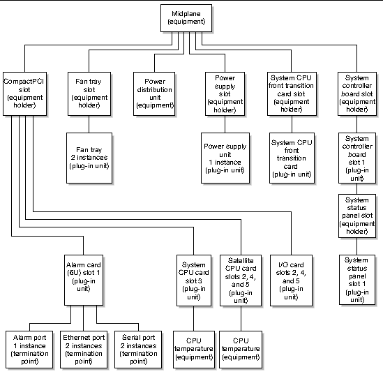
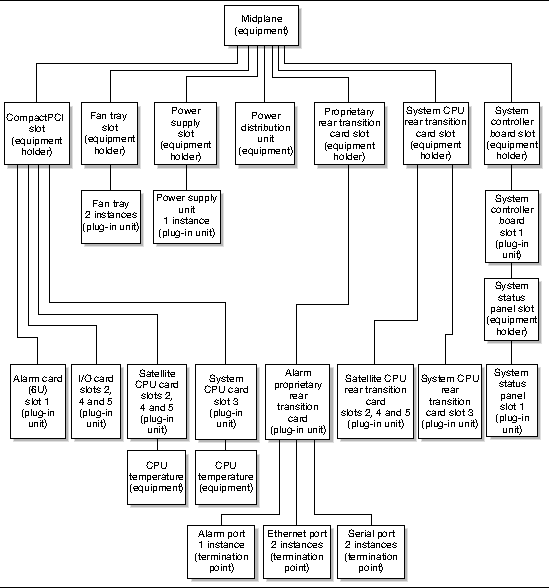
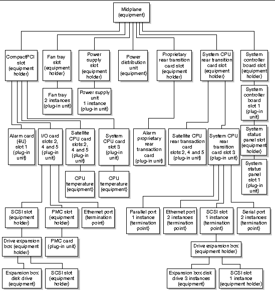
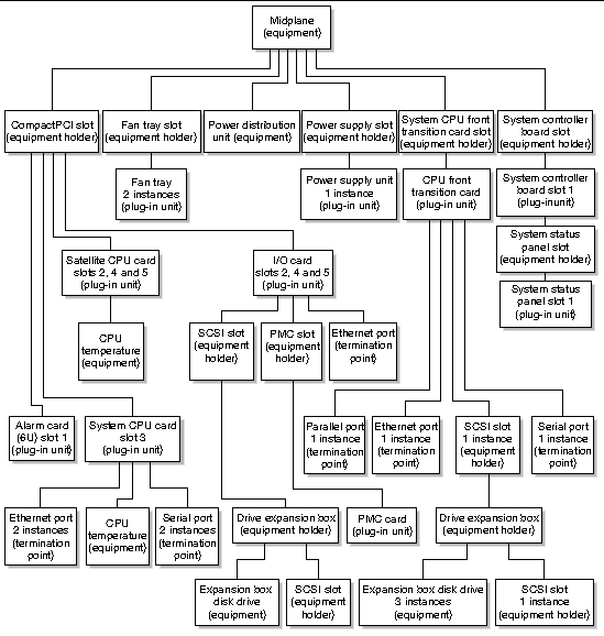
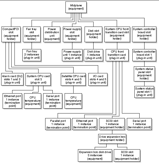
Netra CT 810 System Equipment Models and Netra CT 410 System Equipment Models present the equipment models for the Netra CT front and rear-access systems. These sections contain the equipment models shown in the system alarm card view, the host CPU board view, and the host and satellite CPU board views.


Netra CT 810 System Equipment Models

This section contains the following equipment models of the Netra CT 810 server:
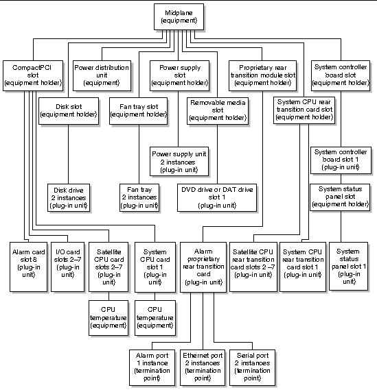
 

  FIGURE 2-3 Rear-Access Netra CT 810 System View From Alarm Card

Diagram showing the rear-access Netra CT 810 system equipment model as seen through the alarm card.[ D ]


  FIGURE 2-4 Front-Access Netra CT 810 System View From Alarm Card

Diagram showing the front-access Netra CT 810 system equipment model as seen through the alarm card.[ D ]


  FIGURE 2-5 Rear-Access Netra CT 810 System View From Host CPU Board

Diagram showing the rear-access Netra CT 810 system equipment model as seen through the host CPU board.[ D ]


  FIGURE 2-6 Front-Access Netra CT 810 System View From Host CPU Board

Diagram showing the front-access Netra CT 810 system equipment model as seen through the host CPU board.[ D ]


  FIGURE 2-7 Front-Access Netra CT 810 System Host CPU Board Local View

Diagram showing the front-access Netra CT 810 system equipment model with the host CPU board as the network element at the top of the hierarchy.[ D ]


  FIGURE 2-8 Rear-Access Netra CT 810 System Host CPU Board Local View

Diagram showing the rear-access Netra CT 810 system equipment model with the host CPU board as the network element at the top of the hierarchy.[ D ]


  FIGURE 2-9 Rear-Access Netra CT 810 System Satellite CPU Board Local View

Diagram showing the rear-access Netra CT 810 system equipment model from the satellite CPU[ D ]


  FIGURE 2-10 Netra CT 810 System Satellite CPU Board Local View

Diagram showing the satellite CPU board as the network element at the top of the hierarchy.[ D ]


Netra CT 410 System Equipment Models

This section contains the following equipment models for the Netra CT 410 server:
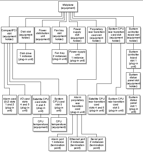
 

  FIGURE 2-11 Rear-Access Netra CT 410 Diskfull System View From Alarm Card

Diagram showing the rear-access Netra CT 410 diskfull system equipment model as seen through the alarm card.[ D ]


  FIGURE 2-12 Front-Access Netra CT 410 Diskfull System View From Alarm Card

Diagram showing the front-access Netra CT 410 diskfull system equipment model as seen through the alarm card.[ D ]


  FIGURE 2-13 Front-Access Netra CT 410 Diskless System View From Alarm Card

Diagram showing the front-access Netra CT 410 diskless system equipment model as seen through the alarm card.[ D ]


  FIGURE 2-14 Rear-Access Netra CT 410 Diskless System View From Alarm Card

Diagram showing the rear-access Netra CT 410 diskless system equipment model as seen through the alarm card.[ D ]


  FIGURE 2-15 Rear-Access Netra CT 410 Diskless System View From Host CPU Board

Diagram showing the rear-access Netra CT 410 diskless system equipment model as seen through the host CPU board.[ D ]

  FIGURE 2-16 Front-Access Netra CT 410 Diskless System View From Host CPU Board

Diagram showing the front-access Netra CT 410 diskless system equipment model as seen through the host CPU board.[ D ]


  FIGURE 2-17 Front-Access Netra CT 410 Diskfull System View From Host CPU Board

Diagram showing the front-access Netra CT 410 diskfull system equipment model as seen through the host CPU board.[ D ]

  FIGURE 2-18 Rear-Access Netra CT 410 Diskfull Local View From Host CPU Board

Diagram showing the rear-access Netra CT 410 diskfull system equipment model with the host CPU board as the network element at the top of the hierarchy.[ D ]


  FIGURE 2-19 Rear-Access Netra CT 410 System Satellite CPU Board Local View

Diagram showing the Netra CT 410 system equipment model with the satellite CPU board as the network element at the top of the hierarchy.[ D ]