| C H A P T E R 8 |
|
Updating the Critical System-Specific Drivers |
This chapter explains how to update the Windows Server 2003 installation with the system-specific device driver software for the Sun Fire X4100 or X4200 server.
| Note - This information applies only to the Sun Fire X4100 and Sun Fire X4200 servers. It does not apply to the Sun Fire X4100 M2 or Sun Fire X4200 M2. |
This chapter contains the following sections:
The procedures in this chapter assume that you already:
To update the system-specific drivers:
1. Copy the InstallPack.exe file from its current location to a local drive on the server.
| Note - A version number that represents the current version of the software update package will also be part of the package name. |
2. Start the InstallPack.exe application.
The files are extracted and the Sun Fire Installation Package dialog box displays.
FIGURE 8-1 Sun Fire Installation Package dialog box
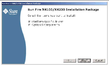
3. Click Next to accept the default settings.
| Note - It is recommended that “platform-specific drivers” always be selected to ensure that the most recent drivers are installed. |
The Important Note dialog box displays.
FIGURE 8-2 Important Note dialog box
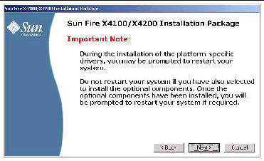
4. Review the important note and then click Next.
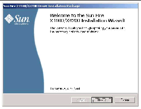
The Welcome to the Sun Fire Installation Wizard dialog box displays.
FIGURE 8-3 Sun Fire X4100/X4200 Installation Wizard dialog box
The End User License Agreement dialog box displays.
FIGURE 8-4 End User License Agreement dialog box
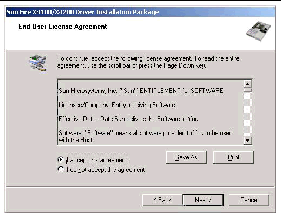
6. To accept the license agreement, click Next.
The installation will continue until the Finished Installing dialog box displays.
FIGURE 8-5 Finished Installing dialog box
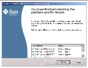
The System Settings Change dialog box displays.
FIGURE 8-6 System Settings Change dialog box

8. If you accepted the default settings in Step 3, click No to proceed to Installing Optional Components.
If you are not installing the Optional Components, click Yes to restart your computer.
For AMD Power Monitor installation, a security alert may display saying that AMD ACPI-compliant system has not been properly authenticated. Click Yes to accept the installation of the driver software, or No to abort.
There are several optional components available for your Sun Fire server. You can select to install the recommended options (Typical), or choose your own set of options (Custom).
|
|
* If selected, these components will install unsigned drivers. The system will continue to operate correctly. |
If you selected No in the previous Step 8, or if you did not select Optional Components in FIGURE 8-1, the Optional Components dialog box displays:
FIGURE 8-7 Optional Components Dialog Box
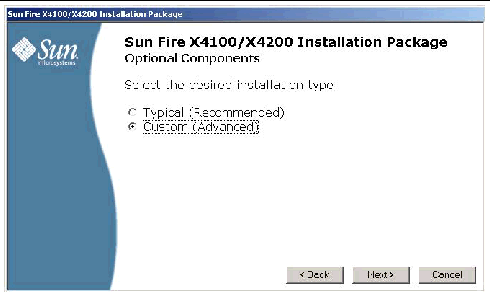
1. Select your installation type:
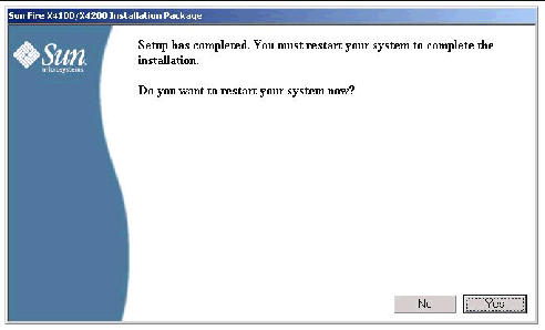
Dialog boxes guide you through the installation of each of the selected optional components. When all selected optional components have been installed, the Sun Fire Setup Completed dialog box will appear, as shown in FIGURE 8-11.
The Optional Components selection dialog box displays.
FIGURE 8-8 Custom Optional Components Selection Dialog Box
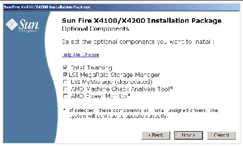
2. Select the optional components to install and click Next to begin installation.
For additional information on the optional components, click “Help Me Choose.”
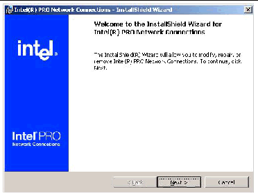
3. In this example, FIGURE 8-9 shows the introductory screen to Intel Teaming. Click Next to continue.
FIGURE 8-9 Intel Teaming Installation Wizard Dialog Box
4. In this example, FIGURE 8-10 shows the introductory screen to the introductory screen to MSM-IR. Click Next to continue.
FIGURE 8-10 MSM-IR Installation Wizard Dialog Box
Further dialog boxes will guide you through the installation of each of the selected optional components. Follow the wizard prompts. When all selected optional components have been installed, the Sun Fire Setup Completed dialog box displays, as shown in FIGURE 8-11.
FIGURE 8-11 Sun Fire Setup Complete Dialog Box
| Note - Some optional components, as indicated in FIGURE 8-8, will install unsigned drivers. Your system will continue to operate normally. During installation each unsigned driver will cause a Driver Installation Security Alert dialog to appear. You should answer Yes to continue the installation. |
This section lists additional information about Sun optional software for your server. This information includes:
The MSM program enables you to configure the LSI Logic integrated RAID controller, physical disk drives, and virtual disk drives on your system. The Configuration Wizard in the MSM program simplifies the process of creating disk groups and virtual disk drives by guiding you through several simple steps to create your storage configurations.
MSM works with the appropriate Operating System (OS) libraries and drivers to configure, monitor, and maintain storage configurations attached to x64 servers. The MSM GUI displays device status in the form of icons, which represent the controllers, virtual disk drives, and physical disk drives on your system. Special icons appear next to the device icons on the screen to notify you of disk failures and other events that require immediate attention. System errors and events are recorded in an event log file and are displayed on the screen.
For information on using MSM, refer to the Sun LSI 106x RAID User’s Guide for your server on the Sun product documentation web site at:
Intel® PROSet for Windows Device Manager is an extension to the Windows Device Manager. When you install the NIC Teaming supplemental software for your Sun server, Intel PROSet software configuration tabs are automatically added to the network adapters listed in Device Manager.
| Note - To determine which network interface ports are active on your system, refer to Appendix B. |
Your Sun Fire X4100 and X4200 has four Intel Ethernet network interface ports. The order in which the server’s BIOS detects these ports during boot-up are as follows:
The device naming for the Ethernet ports differ according to the OS. Windows identifies these ports for the Sun Fire X4100 and X4200 as shown in FIGURE 8-12.
FIGURE 8-12 Sun Fire X4100and X4200 Ethernet Ports

To access the functions available for your server’s network interface, do the following:
1. From the Taskbar, click Start, and then click Run.
The run dialog box is displayed.
2. In the Open list, type devmgmt.msc, and then click OK.
The Device Manager dialog box is displayed.
3. Expand the Network adapters group and select the first adapter.
4. Right-click the selection and click Properties.
The adapter properties dialog box is displayed.
FIGURE 8-13 Intel NIC Adapter Properties

5. To setup NIC teaming, click the Teaming tab.
The teaming options are displayed (see FIGURE 8-13).
6. Select Team with other adapters and then click New Team.
The New Team Wizard is displayed.

7. Click Next. The Adapter Selection page is displayed.
FIGURE 8-15 Adapter Selection Page

8. Select the adapters to be included in the team from the list of installed adapters and then click Next.
The wizard will guide you through the configuration and setup of your team.
For more information on setting up NIC teaming for your environment, refer to the Intel Connectivity web page on “Advanced Networking Services--Teaming” at:
http://support.intel.com/support/network/sb/CS-009747.htm
Additionally, you may download the complete set of Intel Network Connections User Guides for your server’s network adapters at:
http://support.intel.com/support/network/sb/cs-009715.htm
The IPMItool is a command line utility that reads the sensor data repository (SDR) and displays sensor values, System Event Log (SEL), Field Replaceable Unit (FRU) inventory information, gets and sets LAN configuration parameters, and performs chassis power control operations via the server’s Service Processor. IPMItool is supplemental software and may be installed using the server’s Tools and Drivers CD or using the Installpack.exe executable file (described earlier in this chapter).
Once installed, the IPMItool may be used to access your server’s Service Processor (or another Sun server’s Service Processor) in the following ways:
To use IPMItool, ensure that you have completed the requirements specified for your Windows Server 2003 version:
For Windows Server 2003 R2 SP2:
|
Do the following before attempting to use the IPMItool through the Windows operating system:
1. Install the Microsoft IPMI System Management driver:
a. In Control Panel, open Add/Remove Programs.
The Add/Remove Programs dialog is displayed.
b. Click Add/Remove Windows Components.
The Windows Components Wizard dialog is displayed.
c. Highlight Management and Monitoring Tools component, and then click Details.
The Management and Monitoring Tools page is displayed.
e. Read the warning and then click OK.
The Management and Monitoring Tools page is displayed.
The Windows Components Wizard dialog is displayed.
The Hardware Management component is installed.
2. Instantiate the IPMI System Management driver.
3. On the Taskbar, click Start, and then click Run.
The Run dialog box is displayed.
rundll32 ipmisetp.dll,AddTheDevice
The IPMI System Management driver is instantiated.
5. To ensure that the IPMI System Management driver is installed, repeat steps 1a through 1c, above.
For information about using the IPMItool, refer to your Sun Integrated Lights Out Manager 2.0 User’s Guide (820-1188). For more information on standard IPMItool commands, please see:
http://ipmitool.sourceforge.net/manpage.html
Copyright © 2008 Sun Microsystems, Inc. All Rights Reserved.