C H A P T E R  2

Powering On and Configuring BIOS Settings

This chapter contains the following procedures and information:


Note - The information in this chapter applies to all Sun Fire X4100/X4100 M2 and X4200/X4200 M2 servers, unless otherwise noted.


2.1 Powering On the Server


Note - Before powering on your server for the first time, follow the installation and cabling instructions provided in the Sun Fire X4100/X4200 Servers Installation Guide, which is shipped with the system and is also available online at: http://www.sun.com/documentation


caution icon Caution - Do not operate the server without all fans, component heatsinks, air baffles, and covers installed. Severe damage to server components can occur if the server is operated without adequate cooling mechanisms.


1. Verify that power cords have been connected to the server's power supplies and that standby power is on.

In standby power mode, the Power/OK LED on the front panel flashes, indicating that the service processor is working and the system is ready to be fully powered on to main power mode. See FIGURE 2-1 orFIGURE 2-2 for the LED location.

2. Use a nonconducting pointer or stylus to press and release the recessed Power button on the server front panel which is shown in FIGURE 2-1 or FIGURE 2-2.

When main power is applied to the full server, the Power/OK LED next to the Power button lights and remains lit.

FIGURE 2-1 Front Panel of Sun Fire X4100/X4100 M2 Server


Graphic showing the Sun Fire X4100/X4100 M2 server front panel with the power button and Power/OK LED shown on the upper-left.


Figure Legend

1

Power/OK LED

2

Power button


FIGURE 2-2 Front Panel of Sun Fire X4200/X4200 M2 Server


Graphic showing the Sun Fire X4200/X4200 M2 server front panel with the power button and Power/OK LED shown on the upper-left.


Figure Legend

1

Power/OK LED

2

Power button


2.2 Powering Off the Server

1. Choose a method for shutting down the server from main power mode to standby power mode.

When main power is off, the Power/OK LED on the front panel will begin flashing, indicating that the server is in standby power mode.


caution icon Caution - When you use the Power button to enter standby power mode, power is still directed to the Graphics Redirect and Service Processor (GRASP) board and power supply fans, which is indicated when the Power/OK LED is flashing. To completely power off the server, you must disconnect the power cords from the back panel of the server.


2.3 Configuring BIOS Settings

This section describes how to view and modify the BIOS settings.

The Basic Input/Output System (BIOS) has a Setup utility stored in the BIOS flash memory. The Setup utility reports system information and can be used to configure the BIOS settings. The configured data is provided with context-sensitive Help and is stored in the system's battery-backed CMOS RAM. If the configuration stored in the CMOS RAM is invalid, the BIOS settings will default to the original state specified at the factory.

The first BIOS Setup menu screen is displayed. The BIOS Setup utility contains seven menu screens, which are displayed in the following order: Main, Advanced, PCI/PnP, Boot, Security, Chipset, and Exit.

Use the left and right arrow keys to move sequentially back and forth through the seven screens. Fields that can be reconfigured are displayed in color. All other fields are nonconfigurable. Use the up and down arrow keys to scroll through a menu. Use the Tab key to move back and forth across columns.

2.3.1 Changing the Configuration of a BIOS Menu Item

You can change the BIOS configuration in several different interfaces.

1. To change the system parameters, enter the BIOS Setup utility by pressing the F2 key while the system is performing the power-on self-test (POST).

POST testing is indicated when the Power/OK LEDs on the front and back panels go into slow-blink mode.

2. Highlight the field to be modified using the arrow and Tab keys.

3. Press Enter to select the field.

A dialog box is displayed. The box presents you with the options that are available for the setup field that you have chosen.

4. Modify the setup field and close the screen.

5. If you need to modify other setup parameters, use the arrow and Tab keys to navigate to the desired screen and menu item, then repeat steps To change the system parameters, enter the BIOS Setup utility by pressing the F2 key while the system is performing the power-on self-test (POST). through Press Enter to select the field.. Otherwise, go to Step 6.

6. Press and release the right arrow key until the Exit menu screen is displayed.

7. Follow the instructions on the Exit menu screen to save your changes and exit the Setup utility.

2.3.2 PCI Card Slot Boot Priority

Refer to the section that corresponds to your version of the server:

See Replacing PCI Cards for the locations of the PCI slots.

Sun Fire X4100/X4200 Servers PCI Slot Boot Priority

The slots for the PCI cards are detected by the BIOS during startup in the following order:

Sun Fire X4100 M2/X4200 M2 Servers PCI Slot Boot Priority

The slots for the PCI cards are detected by the BIOS during startup in the following order:

2.3.3 Ethernet Port Device and Driver Naming

These servers each have four 10/100/1000BASE-T Gigabit Ethernet ports. The chassis labeling of the physical ports is shown in FIGURE 2-3.

FIGURE 2-3 Ethernet Port Chassis Labeling Designations


Graphic showing the physical labeling of the Ethernet ports.

The device naming for the Ethernet ports differ according to the OS. Refer to the section below that applies to your server:

Sun Fire X4100/X4200 Ethernet Port Mapping

FIGURE 2-4 shows how various operating systems and interfaces name the four Ethernet ports shown in FIGURE 2-3.

FIGURE 2-4 Sun Fire X4100/X4200 Ethernet Port Mapping


Graphic showing Sun Fire X4100/X4200 NIC naming as reported by various software interfaces.


Note - VMWare ESX 3.0.1: The Ethernet port that the user assigns to the service console will be vmnic0. Other ports are mapped by ascending order of PCI bus enumerations.


Sun Fire X4100 M2/X4200 M2 Ethernet Port Mapping

FIGURE 2-5 shows how various operating systems and interfaces name the four Ethernet ports shown in FIGURE 2-3.

FIGURE 2-5 Sun Fire X4100 M2/X4200 M2 Ethernet Port Mapping


Graphic showing Sun Fire X4100 M2/X4200 M2 NIC naming as reported by various software interfaces.


Note - VMWare ESX 3.0.1: The Ethernet port that the user assigns to the service console will be vmnic0. Other ports are mapped by ascending order of PCI bus enumerations.


2.3.4 Ethernet Port (NIC) Boot Priority

Refer to the section that corresponds to your version of the server:

Sun Fire X4100/X4200 Servers Ethernet Port Boot Priority

The order in which the BIOS detects the Ethernet ports during bootup and the corresponding drivers that control those ports are listed below:

1. NET 0 (Intel NIC 0)

2. NET 1 (Intel NIC 1)

3. NET 2 (Intel NIC 2)

4. NET 3 (Intel NIC 3)

Sun Fire X4100 M2/X4200 M2 Servers Ethernet Port Boot Priority

The order in which the BIOS detects the Ethernet ports during bootup and the corresponding drivers that control those ports are listed below:

1. NET 0 (NVIDIA CK8-04 NIC)

2. NET 1 (NVIDIA IO-04 NIC)

3. NET 2 (Intel NIC)

4. NET 3 (Intel NIC)

2.3.5 BIOS Option ROM Size Limitation

The BIOS Option ROM is 128 KB. Of these 128 KB, approximately 80 KB are used by the VGA controller, the LSI controller, and the network interface card. Approximately 48 KB remain for the Option ROM.

2.3.6 BIOS Setup Screen Overview

TABLE 2-1 contains summary descriptions of the seven top-level BIOS setup screens.


TABLE 2-1 BIOS Setup Screens Summary

Screen

Description

Main

General system information.

Advanced

Configuration interface for the CPUs, IDE, SuperIO, ACPI, Event Log, HyperTransport, IPMI, MPS, PCI-Express, PowerNow!, Remote Access, and USB.

PCI/PnP

Plug-and-Play (PnP) devices can be configured by the BIOS (default) or by the operating system (if applicable).

Boot

Configure the boot device priority (hard disk drives and the ATAPI DVD-ROM drive).

Security

Install or change the user and supervisor passwords.

Chipset

Configuration options for the NorthBridge and SouthBridge devices and PCI-X devices.

Note that the Memory Chipkill option is enabled by default. Enabling Chipkill improves system reliability, but degrades system performance under specific applications.

Exit

Save or discard changes.


FIGURE 2-6 and FIGURE 2-7 summarize the BIOS Configuration Utility menu tree, with differences between server models noted. See BIOS Setup Menu Screens for examples of each of these screens.

FIGURE 2-6 Sun Fire X4100/X4200 BIOS Configuration Utility Menu Tree


Sun Fire X4100/X4200 BIOS Configuration Utility screens, summarized as a menu tree with the 7 top-level screens listed horizontally and their sub-screens listed vertically.

FIGURE 2-7 Sun Fire X4100 M2/X4200 M2 BIOS Configuration Utility Menu Tree


Sun Fire X4100 M2/X4200 M2 BIOS Configuration Utility screens, summarized as a menu tree with the 7 top-level screens listed horizontally and their sub-screens listed vertically.

2.3.6.1 BIOS Setup Menu Screens

This section shows sample BIOS setup menu screens with optimal default settings where applicable.


Note - The screens shown are examples. Actual version numbers are subject to change over the life of the product.


BIOS Main Menu Screen
 
Main    Advanced    PCIPnP    Boot    Security    Chipset    Exit
********************************************************************************
* System Overview                                    ** Use [ENTER], [TAB]     *
* ***************************************************** or [SHIFT-TAB] to      *
* AMIBIOS                                            ** select a field.        *
* Version   : 08.00.10                               **                        *
* Build Date: 06/22/05                               ** Use [+] or [-] to      *
* ID        : 0ABGA018                               ** configure system Time. *
*                                                    **                        *
* Product Name          : Sun Fire X4200             ** 
* System Serial Number   : 0525AMF002                									*
* BMC Firmware Revision : 1.00                       **                        *
*                                                    **                        *
* Processor                                          **                        *
* Type      : AMD Opteron(tm) Processor 254          ** **    Select Screen    *
* Speed     : 2.8 GHz                                ** **    Select Item      *
* Count     : 2                                      ** +-    Change Field     *
*                                                    ** Tab   Select Field     *
* System Memory                                      ** F1    General Help     *
* Size      : 3.0 GB                                 ** F10   Save and Exit    *
*                                                    ** ESC   Exit             *
* System Time                    [14:23:56]          ** ESC   Exit             *
* System Date                    [Wed 07/20/2005]    **                        *
********************************************************************************

2.3.6.2 BIOS Advanced Menu Main Screens

Sun Fire X4100/X4200 Servers
 
Main    Advanced    PCIPnP    Boot    Security    Chipset    Exit
********************************************************************************
* Advanced Settings                                   * Options for CPU        *
* *************************************************** *                        *
* WARNING: Setting wrong values in below sections     *                        *
*          may cause system to malfunction.           *                        *
* * CPU Configuration                                 *                        *
* * IDE Configuration                                 *                        *
* * SuperIO Configuration                             *                        *
* * ACPI Configuration                                *                        *
* * Event Log Configuration                           *                        *
* * Hyper Transport Configuration                     *                        *
* * IPMI 2.0 Configuration                            *                        *
* * MPS Configuration                                 * **    Select Screen    *
* * AMD PowerNow Configuration                        * **    Select Item      *
* * Remote Access Configuration                       * Enter Go to Sub Screen *
* * USB Configuration                                 * F1    General Help     *
*                                                     * F10   Save and Exit    *
*                                                     * ESC   Exit             *
********************************************************************************
Sun Fire X4100 M2/X4200 M2 Servers
 
Main    Advanced    PCIPnP    Boot    Security    Chipset    Exit
********************************************************************************
* Advanced Settings                                   * Options for CPU        *
* *************************************************** *                        *
* WARNING: Setting wrong values in below sections     *                        *
*          may cause system to malfunction.           *                        *
* * CPU Configuration                                 *                        *
* * IDE Configuration                                 *                        *
* * SuperIO Configuration                             *                        *
* * ACPI Configuration                                *                        *
* * Event Log Configuration                           *                        *
* * Hyper Transport Configuration                     *                        *
* * IPMI 2.0 Configuration                            *                        *
* * MPS Configuration                                 * **    Select Screen    *
* * PCI Express Configuration                         *                        *
* * AMD PowerNow Configuration                        * **    Select Item      *
* * Remote Access Configuration                       * Enter Go to Sub Screen *
* * USB Configuration                                 * F1    General Help     *
*                                                     * F10   Save and Exit    *
*                                                     * ESC   Exit             *
********************************************************************************

2.3.6.3 BIOS Advanced Menu CPU Configuration Screen

Sun Fire X4100/X4200 Servers
 
          Advanced
********************************************************************************
* CPU Configuration                                   * This option should     *
* Module Version: 14.05                               * remain disabled for    *
* Physical Count: 2                                   * the normal operation.  *
* Logical Count : 2                                   * The driver developer   *
* *************************************************** * may enable it for      *
* AMD Opteron(tm) Processor 254                       * testing purpose.       *
* Revision: E4                                        *                        *
* Cache L1: 64KB                                      *                        *
* Cache L2: 1024KB                                    *                        *
* Speed   : 2800MHz                                   *                        *
* Current FSB Multiplier: 14x                         *                        *
* Maximum FSB Multiplier: 14x                         *                        *
* Able to Change Freq.  : Yes                         * **    Select Screen    *
* uCode Patch Level     : None Required               * **    Select Item      *
*                                                     * +-    Change Option    *
* GART Error Reporting           [Disabled]           * F1    General Help     *
* MTRR Mapping                   [Continuous]         * F10   Save and Exit    *
* Speculative TLB Reload         [Enabled]            * ESC   Exit             *
*                                                     *                        *
********************************************************************************
Sun Fire X4100 M2/X4200 M2 Servers
 
          Advanced
********************************************************************************
* CPU Configuration                                   * This option should     *
* Module Version: 14.05                               * remain disabled for    *
* Physical Count: 2                                   * the normal operation.  *
* Logical Count : 2                                   * The driver developer   *
* *************************************************** * may enable it for      *
* AMD Opteron(tm) Processor 852                       * testing purpose.       *
* Revision: E4                                        *                        *
* Cache L1: 64KB                                      *                        *
* Cache L2: 1024KB                                    *                        *
* Speed   : 2.6 GHz                                   *                        *
* Current FSB Multiplier: 13x                         *                        *
* Maximum FSB Multiplier: 13x                         *                        *
* Able to Change Freq.  : Yes                         * **    Select Screen    *
* uCode Patch Level     : None Required               * **    Select Item      *
*                                                     * +-    Change Option    *
* GART Error Reporting           [Disabled]           * F1    General Help     *
* MTRR Mapping                   [Continuous]         * F10   Save and Exit    *
* CPU Overclock in MHz           [200]                * ESC   Exit             *
* Speculative TLB Reload         [Enabled]            *                        *
*                                                     *                        *
********************************************************************************

2.3.6.4 BIOS Advanced Menu IDE Configuration Screen

Sun Fire X4100/X4200 Servers
 
          Advanced
********************************************************************************
* IDE Configuration                                   * DISABLED: disables the *
* *************************************************** * integrated IDE         *
* OnBoard PCI IDE Controller     [Primary]            * Controller.            *
*                                                     * PRIMARY: enables only  *
* * Primary IDE Master              : [ATAPI CDROM]   * the Primary IDE        *
* * Primary IDE Slave               : [Not Detected]  * Controller.            *
*                                                     * SECONDARY: enables     *
* Hard Disk Write Protect        [Disabled]           * only the Secondary IDE *
* IDE Detect Time Out (Sec)      [5]                  * Controller.            *
*                                                     * BOTH: enables both IDE *
*                                                     * Controllers.           *
*                                                     *                        *
*                                                     * **    Select Screen    *
*                                                     * **    Select Item      *
*                                                     * +-    Change Option    *
*                                                     * F1    General Help     *
*                                                     * F10   Save and Exit    *
*                                                     * ESC   Exit             *
*                                                     *                        *
*                                                     *                        *
********************************************************************************
Sun Fire X4100 M2/X4200 M2 Servers
 
          Advanced
********************************************************************************
* IDE Configuration                                   * DISABLED: disables the *
* *************************************************** * integrated IDE         *
* OnBoard PCI IDE Controller     [Primary]            * Controller.            *
*                                                     * PRIMARY: enables only  *
* * Primary IDE Master              : [ATAPI CDROM]   * the Primary IDE        *
* * Primary IDE Slave               : [Not Detected]  * Controller.            *
*                                                     * SECONDARY: enables     *
* Hard Disk Write Protect        [Disabled]           * only the Secondary IDE *
* IDE Detect Time Out (Sec)      [5]                  * Controller.            *
*                                                     * BOTH: enables both IDE *
* ATA(PI) 80 Pin Cable Detection  [Disabled]          * Controllers.           *
* SATA0 IDE Interface             [Disabled]          *                        *
* SATA1 IDE Interface             [Disabled]          * **    Select Screen    *
* IO4 SATA0 IDE Interface         [Disabled]          * **    Select Item      *
* IO4 SATA1 IDE Interface         [Disabled]          * +-    Change Option    *
* First Boot Device from          [P-ATA]             * F1    General Help     *
*                                                     * F10   Save and Exit    *
*                                                     * ESC   Exit             *
*                                                     *                        *
********************************************************************************

2.3.6.5 BIOS Advanced Menu SuperIO Chipset Configuration Screen

 
          Advanced
********************************************************************************
* Configure Smc27X Super IO Chipset                   * Allows BIOS to Select  *
* *************************************************** * Serial Port1 Base      *
* Serial Port1 Address           [3F8/IRQ4]           * Addresses.             *
*                                                     *                        *
*                                                     *                        *
*                                                     *                        *
*                                                     *                        *
*                                                     *                        *
*                                                     *                        *
*                                                     *                        *
*                                                     *                        *
*                                                     *                        *
*                                                     * **    Select Screen    *
*                                                     * **    Select Item      *
*                                                     * +-    Change Option    *
*                                                     * F1    General Help     *
*                                                     * F10   Save and Exit    *
*                                                     * ESC   Exit             *
*                                                     *                        *
*                                                     *                        *
********************************************************************************

2.3.6.6 BIOS Advanced Menu ACPI Settings Screen

 
          Advanced
********************************************************************************
* ACPI Settings                                       * Yes / No               *
* *************************************************** * ACPI support for       *
* ACPI Aware O/S                 [Yes]                * Operating System.      *
*                                                     *                        *
* * Advanced ACPI Configuration                       * Yes: If OS             *
*                                                     * supports ACPI.         *
*                                                     *                        *
*                                                     * No: If OS              *
*                                                     * does not support       *
*                                                     * ACPI.                  *
*                                                     *                        *
*                                                     *                        *
*                                                     * **    Select Screen    *
*                                                     * **    Select Item      *
*                                                     * +-    Change Option    *
*                                                     * F1    General Help     *
*                                                     * F10   Save and Exit    *
*                                                     * ESC   Exit             *
*                                                     *                        *
*                                                     *                        *
********************************************************************************

2.3.6.7 BIOS Advanced Menu ACPI Configuration Screen

 
          Advanced
********************************************************************************
* Advanced ACPI Configuration                         * Enable RSDP pointers   *
* *************************************************** * to 64-bit Fixed System *
* ACPI 2.0 Features              [Yes]                * Description Tables.    *
* ACPI APIC support              [Enabled]            *                        *
* ACPI SRAT Table                [Enabled]            *                        *
* AMI OEMB table                 [Enabled]            *                        *
* Headless mode                  [Enabled]            *                        *
*                                                     *                        *
*                                                     *                        *
*                                                     *                        *
*                                                     *                        *
*                                                     *                        *
*                                                     * **    Select Screen    *
*                                                     * **    Select Item      *
*                                                     * +-    Change Option    *
*                                                     * F1    General Help     *
*                                                     * F10   Save and Exit    *
*                                                     * ESC   Exit             *
*                                                     *                        *
*                                                     *                        *
********************************************************************************

2.3.6.8 BIOS Advanced Menu Event Logging Details Screen

 
          Advanced
********************************************************************************
* Event Logging details                               * View all unread events *
* *************************************************** * on the Event Log.      *
* View Event Log                                      *                        *
* Mark all events as read                             *                        *
* Clear Event Log                                     *                        *
*                                                     *                        *
*                                                     *                        *
*                                                     *                        *
*                                                     *                        *
*                                                     *                        *
*                                                     *                        *
*                                                     *                        *
*                                                     * **    Select Screen    *
*                                                     * **    Select Item      *
*                                                     * Enter Go to Sub Screen *
*                                                     * F1    General Help     *
*                                                     * F10   Save and Exit    *
*                                                     * ESC   Exit             *
*                                                     *                        *
*                                                     *                        *
********************************************************************************

2.3.6.9 BIOS Advanced Menu HyperTransport Configuration Screen

Sun Fire X4100/X4200 Servers
 
          Advanced
********************************************************************************
* Hyper Transport Configuration                       * The HyperTransport     *
* *************************************************** * link will run at this  *
*                                                     * speed if it is slower  *
* CPU0:CPU1 HT Link Speed        [Auto]               * than or equal to the   *
* CPU0:CPU1 HT Link Width        [Auto]               * system clock and the   *
*                                                     * board is capable.      *
* CPU0:PCI-X0 HT Link Speed      [Auto]               *                        *
* CPU0:PCI-X0 HT Link Width      [Auto]               *                        *
*                                                     *                        *
* CPU0:PCI-X1 HT Link Speed      [Auto]               *                        *
* CPU0:PCI-X1 HT Link Width      [Auto]               *                        *
*                                                     *                        *
*                                                     * **    Select Screen    *
*                                                     * **    Select Item      *
*                                                     * +-    Change Option    *
*                                                     * F1    General Help     *
*                                                     * F10   Save and Exit    *
*                                                     * ESC   Exit             *
********************************************************************************
Sun Fire X4100 M2/X4200 M2 Servers
 
          Advanced
********************************************************************************
* Hyper Transport Configuration                       * The HyperTransport     *
* *************************************************** * link will run at this  *
*                                                     * speed if it is slower  *
* CPU0:CPU1 HT Link Speed        [Auto]               * than or equal to the   *
* CPU0:CPU1 HT Link Width        [Auto]               * system clock and the   *
*                                                     * board is capable.      *
* CPU0:CK804 HT Link Speed       [Auto]               *                        *
* CPU0:CK804 HT Link Width       [Auto]               *                        *
*                                                     *                        *
* CPU0:CPU1 HT Link Speed        [Auto]               *                        *
* CPU0:CPU1 HT Link Width        [Auto]               *                        *
*                                                     *                        *
* CPU1:PCI-X HT Link Speed       [Auto]               *                        *
* CPU1:PCI-X HT Link Width       [Auto]               *                        *
*                                                     * **    Select Screen    *
* PCI-X:IO4  HT Link Speed       [Auto]               * **    Select Item      *
* PCI-X:IO4  HT Link Width       [Auto]               * +-    Change Option    *
*                                                     * F1    General Help     *
*                                                     * F10   Save and Exit    *
*                                                     * ESC   Exit             *
*                                                     *                        *
********************************************************************************

2.3.6.10 BIOS Advanced Menu IPMI Configuration Screen

 
          Advanced
********************************************************************************
* IPMI 2.0 Configuration                              * View all events in the *
* *************************************************** * BMC Event Log.         *
* Status Of BMC                   Working             *                        *
* * View BMC System Event Log                         * It will take up to     *
* Reload BMC System Event Log                         * 60 Seconds approx.     *
* Clear BMC System Event Log                          * to read all            *
* * LAN Configuration                                 * BMC SEL records.       *
* * PEF Configuration                                 *                        *
* BMC Watch Dog Timer Action     [Disabled]           *                        *
*                                                     *                        *
*                                                     * **    Select Screen    *
*                                                     * **    Select Item      *
*                                                     * Enter Go to Sub Screen *
*                                                     * F1    General Help     *
*                                                     * F10   Save and Exit    *
*                                                     * ESC   Exit             *
*                                                     *                        *
********************************************************************************

2.3.6.11 BIOS Advanced Menu IPMI, View BMC Event Log Screen

 
         Advanced
********************************************************************************
* Total Number Of Entries:     36                     * Use +/- to traverse    *
* *************************************************** * the event log.         *
* SEL Entry Number:            [01]                   *                        *
* SEL Record ID:               0100                   *                        *
* SEL Record Type:             02 (System Event)      *                        *
* Event Timestamp:             1166s from SEL init    *                        *
* Generator ID:                0020                   *                        *
* Event Message Format Ver:    04 (IPMI ver 1.5)      *                        *
* Event Sensor Type:           25 (Entity Presence)   *                        *
* Event Sensor Number:         1F                     *                        *
* Event Dir Type:              08                     *                        *
* Event Data:                  00 FF FF               *                        *
*                                                     * **    Select Screen    *
*                                                     * **    Select Item      *
*                                                     * +-    Change Option    *
*                                                     * F1    General Help     *
*                                                     * F10   Save and Exit    *
*                                                     * ESC   Exit             *
********************************************************************************

2.3.6.12 BIOS Advanced Menu IPMI, LAN Configuration Screen

          Advanced
********************************************************************************
* LAN Configuration.                                  * Enter for IP Address   *
* *************************************************** * Configuration.         *
* Channel Number                 [01]                 *                        *
* Channel Number Status:         Channel number is OK *                        *
* * IP Address                                        *                        *
* * MAC Address                                       *                        *
* * Subnet Mask                                       *                        *
*                                                     *                        *
*                                                     *                        *
*                                                     *                        *
*                                                     *                        *
*                                                     *                        *
*                                                     * **    Select Screen    *
*                                                     * **    Select Item      *
*                                                     * Enter Go to Sub Screen *
*                                                     * F1    General Help     *
*                                                     * F10   Save and Exit    *
*                                                     * ESC   Exit             *
*                                                     *                        *
*                                                     *                        *
********************************************************************************

2.3.6.13 BIOS Advanced Menu IPMI, PEF Configuration Screen

 
          Advanced
********************************************************************************
* Set PEF Configuration Parameters Command.           * Enable or Disable PEF  *
* *************************************************** * Support.               *
* PEF SUPPORT                    [Enabled]            * Refer Table 24.6 of    *
* * PEF Action Global Control                         * IPMI Specification 1.5 *
* Alert Startup Delay            [Disabled]           *                        *
* Startup Delay                  [Disabled]           *                        *
* Event Message For PEF Action   [Disabled]           *                        *
*                                                     *                        *
*                                                     *                        *
*                                                     *                        *
*                                                     *                        *
*                                                     * **    Select Screen    *
*                                                     * **    Select Item      *
*                                                     * +-    Change Option    *
*                                                     * F1    General Help     *
*                                                     * F10   Save and Exit    *
*                                                     * ESC   Exit             *
*                                                     *                        *
********************************************************************************

2.3.6.14 BIOS Advanced Menu MPS Configuration Screen

 
          Advanced
********************************************************************************
* MPS Configuration                                   * MPS Revision           *
* *************************************************** *                        *
* MPS Revision                   [1.4]                *                        *
*                                                     *                        *
*                                                     *                        *
*                                                     *                        *
*                                                     *                        *
*                                                     *                        *
*                                                     *                        *
*                                                     *                        *
*                                                     *                        *
*                                                     *                        *
*                                                     * **    Select Screen    *
*                                                     * **    Select Item      *
*                                                     * +-    Change Option    *
*                                                     * F1    General Help     *
*                                                     * F10   Save and Exit    *
*                                                     * ESC   Exit             *
*                                                     *                        *
*                                                     *                        *
********************************************************************************

2.3.6.15 BIOS Advanced Menu PCI Express Configuration Screen

Sun Fire X4100 M2/X4200 M2 Servers Only
 
          Advanced
********************************************************************************
* PCI Express Configuration                           *                        *
* *************************************************** *  Enable/Disable        *
*                                                     *  PCI Express L0s and   *
* Active State Power Management  [Disabled]           *  L1 link power         *
*                                                     *  states                *
*                                                     *                        *
*                                                     *                        *
*                                                     *                        *
*                                                     *                        *
*                                                     * **    Select Screen    *
*                                                     * **    Select Item      *
*                                                     * +-    Change Option    *
*                                                     * F1    General Help     *
*                                                     * F10   Save and Exit    *
*                                                     * ESC   Exit             *
*                                                     *                        *
********************************************************************************

2.3.6.16 BIOS Advanced Menu, AMD PowerNow Configuration

 
         Advanced
********************************************************************************
* AMD PowerNow Configuration                          * Enabled/Disabled       *
* *************************************************** * PowerNow               *
* PowerNow                       [Enabled]            *                        *
*                                                     *                        *
*                                                     *                        *
*                                                     *                        *
*                                                     *                        *
*                                                     *                        *
*                                                     *                        *
*                                                     *                        *
*                                                     *                        *
*                                                     *                        *
*                                                     * **    Select Screen    *
*                                                     * **    Select Item      *
*                                                     * +-    Change Option    *
*                                                     * F1    General Help     *
*                                                     * F10   Save and Exit    *
*                                                     * ESC   Exit             *
*                                                     *                        *
*                                                     *                        *
********************************************************************************

2.3.6.17 BIOS Advanced Menu Remote Access Configuration Screen

 
          Advanced
********************************************************************************
* Configure Remote Access type and parameters         * Select Remote Access   *
* *************************************************** * type.                  *
* Remote Access                  [Enabled]            *                        *
*                                                     *                        *
* Serial port number             [COM1]               *                        *
*      Base Address, IRQ         [3F8h, 4]            *                        *
* Serial Port Mode               [09600 8,n,1]        *                        *
* Flow Control                   [None]               *                        *
* Redirection After BIOS POST    [Always]             *                        *
* Terminal Type                  [ANSI]               *                        *
* VT-UTF8 Combo Key Support      [Enabled]            *                        *
* Sredir Memory Display Delay    [No Delay]           *                        *
*                                                     * **    Select Screen    *
*                                                     * **    Select Item      *
*                                                     * +-    Change Option    *
*                                                     * F1    General Help     *
*                                                     * F10   Save and Exit    *
*                                                     * ESC   Exit             *
*                                                     *                        *
*                                                     *                        *
********************************************************************************

2.3.6.18 BIOS Advanced Menu USB Configuration Screen

Sun Fire X4100/X4200 Servers
 
          Advanced
********************************************************************************
* USB Configuration                                   * Enables support for    *
* *************************************************** * legacy USB. AUTO       *
* Module Version - 2.23.0-7.4                         * option disables        *
*                                                     * legacy support if      *
* USB Devices Enabled :                               * no USB devices are     *
*   1 Keyboard, 1 Mouse, 1 Hub, 2 Drives              * connected.             *
*                                                     *                        *
* Legacy USB Support             [Enabled]            *                        *
* Hotplug USB FDD Support        [Auto]               *                        *
* Hotplug USB CDROM Support      [Auto]               *                        *
*                                                     *                        *
* * USB Mass Storage Device Configuration             *                        *
*                                                     * **    Select Screen    *
*                                                     * **    Select Item      *
*                                                     * +-    Change Option    *
*                                                     * F1    General Help     *
*                                                     * F10   Save and Exit    *
*                                                     * ESC   Exit             *
********************************************************************************
Sun Fire X4100 M2/X4200 M2 Servers
 
          Advanced
********************************************************************************
* USB Configuration                                   * Enables support for    *
* *************************************************** * legacy USB. AUTO       *
* Module Version - 2.24.0-F.4                         * option disables        *
*                                                     * legacy support if      *
* USB Devices Enabled :                               * no USB devices are     *
*   1 Keyboard, 1 Mouse, 1 Hub, 2 Drives              * connected.             *
*                                                     *                        *
* USB Controller Support         [USB1.1+USB2.0]      *                        *
* Legacy USB Support             [Enabled]            *                        *
* USB 2.0 Controller Mode        [HiSpeed]            *                        *
* BIOS EHCI Hand-off             [Enabled]            *                        *
* Hotplug USB FDD Support        [Auto]               *                        *
* Hotplug USB CDROM Support      [Auto]               *                        *
*                                                     *                        *
* * USB Mass Storage Device Configuration             *                        *
*                                                     * **    Select Screen    *
*                                                     * **    Select Item      *
*                                                     * +-    Change Option    *
*                                                     * F1    General Help     *
*                                                     * F10   Save and Exit    *
*                                                     * ESC   Exit             *
********************************************************************************

2.3.6.19 BIOS PCI/PnP Menu

Sun Fire X4100/X4200 Servers
 
  Main    Advanced    PCIPnP    Boot    Security    Chipset    Exit
********************************************************************************
* Advanced PCI/PnP Settings                          ** NO: lets the BIOS      *
* ***************************************************** configure all the      *
* WARNING: Setting wrong values in below sections    ** devices in the system. *
*          may cause system to malfunction.          ** YES: lets the          *
*                                                    ** operating system       *
* Plug & Play O/S                [No]                ** configure Plug and     *
* PCI Latency Timer              [64]                ** Play (PnP) devices not *
* Allocate IRQ to PCI VGA        [Yes]               ** required for boot if   *
* Palette Snooping               [Disabled]          ** your system has a Plug *
* PCI IDE BusMaster              [Disabled]          ** and Play operating     *
* OffBoard PCI/ISA IDE Card      [Auto]              ** system.                *
* Onboard LSI SAS/SATA           [Enabled]           **                        *
* Onboard PCI NIC                [Enabled]           ** **    Select Screen    *
* PCIX SLOT1                     [Enabled]           ** **    Select Item      *
* PCIX SLOT2                     [Enabled]           ** +-    Change Option    *
* PCIX SLOT3                     [Enabled]           ** F1    General Help     *
* PCIX SLOT4                     [Enabled]           ** F10   Save and Exit    *
* PCIX SLOT5                     [Enabled]           ** ESC   Exit             *
* Onboard PCI NIC MAC Address                        **                        *
*   GE NIC 1 : 00 03 BA CD 51 39                     **                        *
*   GE NIC 2 : 00 03 BA CD 51 38                     ** Available: Specified   *
*   GE NIC 3 : 00 03 BA CD 51 3B                     ** DMA is available to be *
*   GE NIC 3 : 00 03 BA CD 51 3B                     ** used by PCI/PnP        *
*                                                    ** devices.               *
* IRQ3                           [Available]         ** Reserved: Specified    *
* IRQ4                           [Reserved]          ** DMA is reserved for    *
* IRQ5                           [Available]         ** use by legacy ISA      *
* IRQ7                           [Available]         ** devices.               *
* IRQ9                           [Available]         **                        *
* IRQ10                          [Available]         **                        *
* IRQ11                          [Available]         **                        *
* IRQ14                          [Available]         **                        *
* IRQ15                          [Available]         ** **    Select Screen    *
*                                                    ** **    Select Item      *
* DMA Channel 0                  [Available]         ** +-    Change Option    *
* DMA Channel 1                  [Available]         ** F1    General Help     *
* DMA Channel 3                  [Available]         ** F10   Save and Exit    *
* DMA Channel 5                  [Available]         ** ESC   Exit             *
* DMA Channel 6                  [Available]         **                        *
* DMA Channel 7                  [Available]         **                        *
*                                                    **                        *
* Reserved Memory Size           [Disabled]          **                        *
********************************************************************************
Sun Fire X4100 M2/X4200 M2 Servers
 
  Main    Advanced    PCIPnP    Boot    Security    Chipset    Exit
********************************************************************************
* Advanced PCI/PnP Settings                          ** NO: lets the BIOS      *
* ***************************************************** configure all the      *
* WARNING: Setting wrong values in below sections    ** devices in the system. *
*          may cause system to malfunction.          **                        *
*                                                    ** YES: lets the          *
* Clear NVRAM                    [No]                ** operating system       *
* Plug & Play O/S                [No]                ** configure Plug and     *
* PCI Latency Timer              [64]                ** Play (PnP) devices not *
* Allocate IRQ to PCI VGA        [Yes]               ** required for boot if   *
* Palette Snooping               [Disabled]          ** your system has a Plug *
* PCI IDE BusMaster              [Disabled]          ** and Play operating     *
* OffBoard PCI/ISA IDE Card      [Auto]              ** system.                *
* PCI Option ROM control         [Enabled]           **                        *
* Scanning onboard SAS/SATA ROM  [Enabled]           **                        *
* Scanning onboard NIC OPROM     [Enabled]           ** **    Select Screen    *
* Scanning OPROM on PCIE SLOT0   [Enabled]           ** **    Select Item      *
* Scanning OPROM on PCIE SLOT1   [Enabled]           ** +-    Change Option    *
* Scanning OPROM on PCIX SLOT2   [Enabled]           ** F1    General Help     *
* Scanning OPROM on PCIE SLOT3   [Enabled]           ** F10   Save and Exit    *
* Scanning OPROM on PCIE SLOT4   [Enabled]           ** ESC   Exit             *
* Onboard PCI NIC MAC Address                        **                        *
*   Nvidia CK804 NIC 1 : 00 03 BA CD 51 39           **                        *
*   Nvidia IO4 NIC 2   : 00 03 BA CD 51 38           ** Available: Specified   *
*   Intel GiGE NIC 3   : 00 03 BA CD 51 3B           ** DMA is available to be *
*   Intel GiGE NIC 3   : 00 03 BA CD 51 3B           ** used by PCI/PnP        *
*                                                    ** devices.               *
* IRQ3                           [Available]         ** Reserved: Specified    *
* IRQ4                           [Reserved]          ** DMA is reserved for    *
* IRQ5                           [Available]         ** use by legacy ISA      *
* IRQ7                           [Available]         ** devices.               *
* IRQ9                           [Available]         **                        *
* IRQ10                          [Available]         **                        *
* IRQ11                          [Available]         **                        *
* IRQ14                          [Available]         **                        *
* IRQ15                          [Available]         ** **    Select Screen    *
*                                                    ** **    Select Item      *
* DMA Channel 0                  [Available]         ** +-    Change Option    *
* DMA Channel 1                  [Available]         ** F1    General Help     *
* DMA Channel 3                  [Available]         ** F10   Save and Exit    *
* DMA Channel 5                  [Available]         ** ESC   Exit             *
* DMA Channel 6                  [Available]         **                        *
* DMA Channel 7                  [Available]         **                        *
*                                                    **                        *
* Reserved Memory Size           [Disabled]          **                        *
********************************************************************************

2.3.6.20 BIOS Boot Menu Main Screen

 
  Main    Advanced    PCIPnP    Boot    Security    Chipset    Exit
********************************************************************************
* Boot Settings                                       * Configure Settings     *
* *************************************************** * during System Boot.    *
* * Boot Settings Configuration                       *                        *
*                                                     *                        *
* * Boot Device Priority                              *                        *
* * Hard Disk Drives                                  *                        *
* * Removable Drives                                  *                        *
* * CD/DVD Drives                                     *                        *
*                                                     *                        *
*                                                     *                        *
*                                                     *                        *
*                                                     *                        *
*                                                     * **    Select Screen    *
*                                                     * **    Select Item      *
*                                                     * Enter Go to Sub Screen *
*                                                     * F1    General Help     *
*                                                     * F10   Save and Exit    *
*                                                     * ESC   Exit             *
*                                                     *                        *
*                                                     *                        *
********************************************************************************

2.3.6.21 BIOS Boot Settings Configuration Screen

 
                                Boot
********************************************************************************
* Boot Settings Configuration                         * Allows BIOS to skip    *
* *************************************************** * certain tests while    *
* Quick Boot                     [Disabled]           * booting. This will     *
* System Configuration Display   [Disabled]           * decrease the time      *
* Quiet Boot                     [Disabled]           * needed to boot the     *
* Language                       [English]            * system.                *
* AddOn ROM Display Mode         [Force BIOS]         *                        *
* Bootup Num-Lock                [On]                 *                        *
* Wait For 'F1' If Error         [Disabled]           *                        *
* Interrupt 19 Capture           [Disabled]           *                        *
* Default Boot Order             [CRHB]               *                        *
*                                                     *                        *
*                                                     * **    Select Screen    *
*                                                     * **    Select Item      *
*                                                     * +-    Change Option    *
*                                                     * F1    General Help     *
*                                                     * F10   Save and Exit    *
*                                                     * ESC   Exit             *
*                                                     *                        *
*                                                     *                        *
********************************************************************************

2.3.6.22 BIOS Boot Menu Boot Device Priority Screen

Sun Fire X4100/X4200 Servers
 
                                Boot
********************************************************************************
* Boot Device Priority                                * Specifies the boot     *
* *************************************************** * sequence from the      *
*                                                     * available devices.     *
* 1st Boot Device                [CD/DVD Drives]      *                        *
* 2nd Boot Device                [Removable Dev.]     * A device enclosed in   *
* 3rd Boot Device                [Hard Drive]         * parenthesis has been   *
* 4th Boot Device                [IBA GE Slot 0108 v] * disabled in the        *
* 5th Boot Device                [IBA GE Slot 0109 v] * corresponding type     *
* 6th Boot Device                [IBA GE Slot 0110 v] * menu.                  *
* 7th Boot Device                [IBA GE Slot 0111 v] *                        *
*                                                     *                        *
*                                                     * **    Select Screen    *
*                                                     * **    Select Item      *
*                                                     * +-    Change Option    *
*                                                     * F1    General Help     *
*                                                     * F10   Save and Exit    *
*                                                     * ESC   Exit             *
*                                                     *                        *
********************************************************************************
Sun Fire X4100 M2/X4200 M2 Servers
 
                                Boot
********************************************************************************
* Boot Device Priority                                * Specifies the boot     *
* *************************************************** * sequence from the      *
*                                                     * available devices.     *
* 1st Boot Device                [CD/DVD CDROM]       *                        *
* 2nd Boot Device                [Removable Dev.]     * A device enclosed in   *
* 3rd Boot Device                [Hard Drive]         * parenthesis has been   *
* 4th Boot Device                [NVidia Boot Agent:] * disabled in the        *
* 5th Boot Device                [2-NVidia Boot Agent] * corresponding type     *
* 6th Boot Device                [Network:IBA GE Slo] * menu.                  *
* 7th Boot Device                [Network:IBA GE Slo] *                        *
*                                                     *                        *
*                                                     * **    Select Screen    *
*                                                     * **    Select Item      *
*                                                     * +-    Change Option    *
*                                                     * F1    General Help     *
*                                                     * F10   Save and Exit    *
*                                                     * ESC   Exit             *
*                                                     *                        *
********************************************************************************

2.3.6.23 BIOS Boot Menu Hard Disk Drives Screen

 
                                Boot
********************************************************************************
* Hard Disk Drives                                    * Specifies the boot     *
* *************************************************** * sequence from the      *
* 1st Drive                      [#218 ID00 LUN0 FUJ] * available devices.     *
*                                                     *                        *
*                                                     *                        *
*                                                     *                        *
*                                                     *                        *
*                                                     *                        *
*                                                     *                        *
*                                                     *                        *
*                                                     *                        *
*                                                     *                        *
*                                                     * **    Select Screen    *
*                                                     * **    Select Item      *
*                                                     * +-    Change Option    *
*                                                     * F1    General Help     *
*                                                     * F10   Save and Exit    *
*                                                     * ESC   Exit             *
*                                                     *                        *
*                                                     *                        *
********************************************************************************

2.3.6.24 BIOS Boot Menu Removable Drives Screen

 
                                Boot
********************************************************************************
* Removable Drives                                    * Specifies the boot     *
* *************************************************** * sequence from the      *
* 1st Drive                      [USB:AMI Virtual Fl] * available devices.     *
*                                                     *                        *
*                                                     *                        *
*                                                     *                        *
*                                                     *                        *
*                                                     *                        *
*                                                     *                        *
*                                                     *                        *
*                                                     *                        *
*                                                     *                        *
*                                                     * **    Select Screen    *
*                                                     * **    Select Item      *
*                                                     * +-    Change Option    *
*                                                     * F1    General Help     *
*                                                     * F10   Save and Exit    *
*                                                     * ESC   Exit             *
*                                                     *                        *
*                                                     *                        *
********************************************************************************

2.3.6.25 BIOS Boot Menu CD/DVD Drives Screen

 
                                Boot
********************************************************************************
* CD/DVD Drives                                  * Specifies the boot     *
* *************************************************** * sequence from the      *
* 1st Drive                      [CD/DVD:PM-QSI DVD]  * available devices.     *
* 2nd Drive                      [USB:AMI Virtual CD] *                        *
*                                                     *                        *
*                                                     *                        *
*                                                     *                        *
*                                                     *                        *
*                                                     *                        *
*                                                     *                        *
*                                                     *                        *
*                                                     *                        *
*                                                     * **    Select Screen    *
*                                                     * **    Select Item      *
*                                                     * +-    Change Option    *
*                                                     * F1    General Help     *
*                                                     * F10   Save and Exit    *
*                                                     * ESC   Exit             *
*                                                     *                        *
*                                                     *                        *
********************************************************************************

2.3.6.26 BIOS Security Settings Menu

 
   Main    Advanced    PCIPnP    Boot    Security    Chipset    Exit
********************************************************************************
* Security Settings                                   * Install or Change the  *
* *************************************************** * password.              *
* Supervisor Password :Not Installed                  *                        *
* User Password       :Not Installed                  *                        *
*                                                     *                        *
* Change Supervisor Password                          *                        *
* Change User Password                                *                        *
* Clear User Password                                 *                        *
*                                                     *                        *
* Boot Sector Virus Protection   [Disabled]           *                        *
*                                                     *                        *
*                                                     *                        *
*                                                     * **    Select Screen    *
*                                                     * **    Select Item      *
*                                                     * Enter Change           *
*                                                     * F1    General Help     *
*                                                     * F10   Save and Exit    *
*                                                     * ESC   Exit             *
*                                                     *                        *
*                                                     *                        *
********************************************************************************

2.3.6.27 BIOS Chipset Menu Main Screen

Sun Fire X4100/X4200 Servers
 
  Main    Advanced    PCIPnP    Boot    Security    Chipset    Exit
********************************************************************************
*                                                     * Options for NB         *
* * NorthBridge Configuration                         *                        *
* * SouthBridge Configuration                         *                        *
* * PCI-X Configuration                               *                        *
*                                                     *                        *
*                                                     *                        *
*                                                     *                        *
*                                                     *                        *
*                                                     * **    Select Screen    *
*                                                     * **    Select Item      *
*                                                     * Enter Go to Sub Screen *
*                                                     * F1    General Help     *
*                                                     * F10   Save and Exit    *
*                                                     * ESC   Exit             *
*                                                     *                        *
*                                                     *                        *
********************************************************************************
Sun Fire X4100 M2/X4200 M2 Servers
 
  Main    Advanced    PCIPnP    Boot    Security    Chipset    Exit
********************************************************************************
*                                                     * Options for NB         *
* * NorthBridge Configuration                         *                        *
* * SouthBridge Configuration                         *                        *
* *                                                   *                        *
*                                                     *                        *
*                                                     *                        *
*                                                     *                        *
*                                                     *                        *
*                                                     *                        *
*                                                     * **    Select Screen    *
*                                                     * **    Select Item      *
*                                                     * Enter Go to Sub Screen *
*                                                     * F1    General Help     *
*                                                     * F10   Save and Exit    *
*                                                     * ESC   Exit             *
*                                                     *                        *
*                                                     *                        *
********************************************************************************

2.3.6.28 BIOS Chipset Menu NorthBridge Configuration Screen

 
                                                    Chipset
********************************************************************************
* NorthBridge Chipset Configuration                   *                        *
* *************************************************** *                        *
* * Memory Configuration                              *                        *
* * ECC Configuration                                 *                        *
* Power Down Control             [Auto]               *                        *
* *************************************************** *                        *
* Memory Timing Parameters       [CPU Node 0]         *                        *
*   Memory CLK             :200 MHz                   *                        *
*   CAS Latency(Tcl)       :3.0                       *                        *
*   RAS/CAS Delay(Trcd)    :3 CLK                     *                        *
*   Min Active RAS(Tras)   :8 CLK                     *                        *
*   Row Precharge Time(Trp):3 CLK                     * **    Select Screen    *
*   RAS/RAS Delay(Trrd)    :2 CLK                     * **    Select Item      *
*   Row Cycle (Trc)        :11 CLK                    * Enter Go to Sub Screen *
*   Row Refresh Cycle(Trfc):14 CLK                    * F1    General Help     *
*   Read Write Delay(Trwt) :4 CLK                     * F10   Save and Exit    *
*   Read Preamble          :7.0 ns                    * ESC   Exit             *
*   Asynchronous Latency   :8 ns                      *                        *
*                                                     *                        *
********************************************************************************

2.3.6.29 BIOS Chipset Menu NorthBridge Memory Configuration Screen

 
                                                    Chipset
********************************************************************************
* Memory Configuration                                * MEMCLK can be set      *
* *************************************************** * by the code using      *
* Memclock Mode                  [Auto]               * AUTO, or if you use    *
* MCT Timing Mode                [Auto]               * LIMIT, you can set     *
* User Config Mode               [Auto]               * one of the standard    *
* Bank Interleaving              [Auto]               * values.                *
* Burst Length                   [4 Beats]            *                        *
* Enable Clock to All DIMMs      [Disabled]           *                        *
* SoftWare Memory Hole           [Disabled]           *                        *
* HardWare Memory Hole           [Disabled]           *                        *
* Node Interleaving              [Disabled]           *                        *
*                                                     *                        *
*                                                     * **    Select Screen    *
*                                                     * **    Select Item      *
*                                                     * +-    Change Option    *
*                                                     * F1    General Help     *
*                                                     * F10   Save and Exit    *
*                                                     * ESC   Exit             *
*                                                     *                        *
********************************************************************************

2.3.6.30 BIOS Chipset Menu NorthBridge ECC Configuration Screen

 
                                                    Chipset
********************************************************************************
* ECC Configuration                                   * DRAM ECC allows        *
* *************************************************** * hardware to report     *
* DRAM ECC Enable                [Enabled]            * and correct memory     *
*   MCA DRAM ECC Logging         [Enabled]            * errors automatically   *
*   ECC Chip Kill                [Enabled]            * maintaining system     *
*   DRAM SCRUB REDIRECT          [Disabled]           * integrity.             *
*   DRAM BG Scrub                [Disabled]           *                        *
* L2 Cache BG Scrub              [Disabled]           *                        *
* Data Cache BG Scrub            [Disabled]           *                        *
*                                                     *                        *
*                                                     *                        *
*                                                     *                        *
*                                                     * **    Select Screen    *
*                                                     * **    Select Item      *
*                                                     * +-    Change Option    *
*                                                     * F1    General Help     *
*                                                     * F10   Save and Exit    *
*                                                     * ESC   Exit             *
*                                                     *                        *
*                                                     *                        *
********************************************************************************

2.3.6.31 BIOS Chipset Menu SouthBridge Configuration Screen

Sun Fire X4100/X4200 Servers
 
                                                   Chipset
********************************************************************************
* South Bridge Chipset Configuration                  * Enable/disable         *
* *************************************************** * SMBUS 2.0 Controller   *
* 2.0 SM Bus Controller          [Enabled]            * in South Bridge        *
* Restore on AC/Power Loss       [Power Off]          *                        *
* Power Button Behavior          [Instant Off]        *                        *
*                                                     *                        *
* HT Link 0 P-Comp Mode          [Auto]               *                        *
* HT Link 0 N-Comp Mode          [Auto]               *                        *
* HT Link 0 RZ-Comp Mode         [Auto]               *                        *
*                                                     *                        *
*                                                     * **    Select Screen    *
*                                                     * **    Select Item      *
*                                                     * +-    Change Option    *
*                                                     * F1    General Help     *
*                                                     * F10   Save and Exit    *
*                                                     * ESC   Exit             *
*                                                     *                        *
********************************************************************************
Sun Fire X4100 M2/X4200 M2 Servers
 
                                                   Chipset
********************************************************************************
* South Bridge Chipset Configuration                  * Enable/disable         *
* *************************************************** * SMBUS 2.0 Controller   *
* SM Bus Interface               [Enabled]            * in South Bridge        *
*                                                     *                        *
* MAC Interface                  [Enabled]            *                        *
* IO4 Interface                  [Enabled]            *                        *
* MAC Bridge Mode                [Enabled]            *                        *
* MAC Media Interface            [Enabled]            *                        *
* MAC Option ROM                 [Enabled]            *                        *
*                                                     *                        *
* Onboard IO APIC                [Enabled]            *                        *
*                                                     *                        *
* CPU Spread spectrum            [Disabled]           *                        *
* SATA Spread spectrum           [Disabled]           *                        *
* PCI-Express Spread spectrum    [Disabled]           *                        *
*                                                     *                        *
* Primary Video                  [Master PCI-Express] * **    Select Screen    *
*                                                     * **    Select Item      *
*                                                     * +-    Change Option    *
* Restore on AC/Power Loss       [Power Off]          * F1    General Help     *
* Power Button Behavior          [Instant Off]        * F10   Save and Exit    *
*                                                     * ESC   Exit             *
********************************************************************************

2.3.6.32 BIOS Chipset Menu PCI-X Configuration Screen

Sun Fire X4100/X4200 Servers Only
 
                                                    Chipset
********************************************************************************
* PCI-X Chipset Configuration                         * PCI clock is disabled/ *
* *************************************************** * enabled for 8131       *
* Errata 56 PCLK                 [Enabled]            * Errata 56 if a PCI     *
* HT Link 0 P-Comp Mode          [Auto]               * card behind 8131       *
* HT Link 0 N-Comp Mode          [Auto]               * bridge has more than   *
* HT Link 0 RZ-Comp Mode         [Auto]               * 4 functions and bus    *
* HT Link 1 P-Comp Mode          [Auto]               * speed is 133 MHz.      *
* HT Link 1 N-Comp Mode          [Auto]               *                        *
* HT Link 1 RZ-Comp Mode         [Auto]               *                        *
*                                                     *                        *
*                                                     * **    Select Screen    *
*                                                     * **    Select Item      *
*                                                     * +-    Change Option    *
*                                                     * F1    General Help     *
*                                                     * F10   Save and Exit    *
*                                                     * ESC   Exit             *
*                                                     *                        *
********************************************************************************

2.3.6.33 BIOS Exit Option Menu Screen

 
  Main    Advanced    PCIPnP    Boot    Security    Chipset    Exit
********************************************************************************
* Exit Options                                        * Exit system setup      *
* *************************************************** * after saving the       *
* Save Changes and Exit                               * changes.               *
* Discard Changes and Exit                            *                        *
* Discard Changes                                     * F10 key can be used    *
*                                                     * for this operation.    *
* Load Optimal Defaults                               *                        *
*                                                     *                        *
*                                                     *                        *
*                                                     *                        *
*                                                     *                        *
*                                                     * **    Select Screen    *
*                                                     * **    Select Item      *
*                                                     * Enter Go to Sub Screen *
*                                                     * F1    General Help     *
*                                                     * F10   Save and Exit    *
*                                                     * ESC   Exit             *
*                                                     *                        *
*                                                     *                        *
********************************************************************************


2.4 Resetting SP and BIOS Passwords Using Jumper P4 or J12

The names and locations of this jumper differ between the Sun Fire X4100/X4200 and the X4100 M2/X4200 M2 servers:

This procedure describes how to reset the Administration password (the root password) for the ILOM Service Processor back to the default after it has been set once during initial setup.


Note - This procedure simultaneously removes any BIOS password that was set.


1. Shut down the server to standby power mode by using a nonconducting pointer or stylus to press and release the recessed Power button on the front panel.

See Powering Off the Server.

2. Disconnect the power cords from the server.


caution icon Caution - Before handling components, attach an ESD wrist strap to the grounding post that is built into the rear of the chassis (see Sun Fire X4100/X4100 M2 Server Back Panelor Sun Fire X4200/X4200 M2 Server Back Panelfor the location). The system’s printed circuit boards and hard disk drives contain components that are extremely sensitive to static electricity.


3. If the server is in a rack, slide it far enough from the rack so that you can remove the main cover. If you cannot safely view and access the motherboard, remove the server from the rack.

4. Remove the main cover from the server.

See Removing the Main Cover of the Sun Fire X4100/X4100 M2 Server or Removing the Main Cover of the Sun Fire X4200/X4200 M2 Servers.

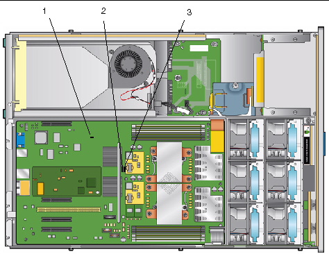
5. Install the shorting jumper across the P4 or J12 header pins.

See FIGURE 2-8 or FIGURE 2-9 for the jumper location. This jumper’s function is to clear the ILOM SP password.

6. Reinstall the main cover to the server.

7. Reconnect power cords to the server.

The server powers up to standby power mode, indicated when the Power/OK LED on the front panel is flashing.

8. Return the server to main power mode by using a nonconducting pointer or stylus to press and release the recessed Power button on the front panel.


Note - You must allow the entire server, not just the SP, to reboot to main power mode to complete the password reset. This is because the state of this jumper cannot be determined without the host CPU running. Wait until the end of POST, when you see the CMOS password cleared by jumper message, after which both the BIOS and SP passwords are reset.


9. Log in to the ILOM web GUI using root as the username and changeme as the password. Refer to the Integrated Lights Out Manager Administration Guide, 819-1160.

10. Change the default password to a password of your choice.

11. Repeat steps Shut down the server to standby power mode by using a nonconducting pointer or stylus to press and release the recessed Power button on the front panel. through Return the server to main power mode by using a nonconducting pointer or stylus to press and release the recessed Power button on the front panel. to remove the P4 or J12 jumper. (Remove the jumper in Step 5 rather than inserting it.)


Note - If you do not remove this jumper, the ILOM SP and BIOS passwords will be reset every time you power-cycle the server.


FIGURE 2-8 Location of Jumpers on the Sun Fire X4100/X4200 Motherboard


Graphic showing the locations of the jumpers on the Sun Fire X4100 M2/X4200 M2 motherboard.


Figure Legend

1

P4, Password Clear

2

P5, Force Recovery

3

TP51/TP52, CMOS Clear


FIGURE 2-9 Location of Jumpers on the Sun Fire X4100 M2/X4200 M2 Motherboard


Figure Legend

1

J9, CMOS Clear

2

J12, Password Clear

3

J13, Force Recovery


2.4.1 Resetting the SP Password

If the ILOM BIOS SP password needs to be reset, do the following to reset the SP and CMOS passwords:

1. Determine if the ILOM SP first-level booter (U-Boot) is intact. Follow documented procedures to connect to the SP serial port, apply power to the system, and observe the initial ILOM boot messages.

See Sun Fire X4500/X4540 Server Installation Guide for details.

2. Enter the ILOM SP U-Boot command interpreter with xyzzy.

When the message, Booting linux in 2 seconds... is displayed, during ILOM initial boot, type xyzzy to enter the U-Boot command interpreter.


Note - The characters typed does not echo. Cutting and pasting the characters improves the chance of success. You might try cycling power to the system and entering xyzzy several times.


3. Disable automatic reboot.

Set the uboot environment variable, bootretry, to -1 to temporarily disable automatic reboot:

    set bootretry -1

4. Configure to not save the current configuration:

    set preserve_conf no

5. Save your current environment:

    saveenv

6. Reboot:

    boot 


2.5 Using the Force-Recovery Jumper P5 or J13

The names and locations of this jumper differ between the Sun Fire X4100/X4200 and the X4100 M2/X4200 M2 servers:

You can use this jumper to force the server to flash a new BIOS in the case of a system freeze. For example, if the system freezes after an ILOM SP firmware/BIOS update, use this procedure to force the server to look for the new BIOS.

1. Shut down the server to standby power mode by using a nonconducting pointer or stylus to press and release the recessed Power button on the front panel. See Powering Off the Server.

2. Disconnect the power cords from the server.


caution icon Caution - Before handling components, attach an ESD wrist strap to the grounding post that is built into the rear of the chassis (see Sun Fire X4100/X4100 M2 Server Back Panelor Sun Fire X4200/X4200 M2 Server Back Panelfor the location). The system’s printed circuit boards and hard disk drives contain components that are extremely sensitive to static electricity.


3. If the server is in a rack, slide it far enough from the rack so that you can remove the main cover. If you cannot safely view and access the motherboard, remove the server from the rack.

4. Remove the main cover from the server. See one of the following:

5. Install the shorting jumper across the P5 or J13 header pins.

See FIGURE 2-8 or FIGURE 2-9 for the jumper location. This jumper’s function is to instruct the system to force recovery of the latest BIOS at system reboot.

6. Reinstall the main cover to the server.

7. Reconnect power cords to the server.

The server powers up to standby power mode, which is indicated when the Power/OK LED on the front panel is flashing.

8. Return the server to main power mode by using a nonconducting pointer or stylus to press and release the recessed Power button on the front panel.

You must fully power on the server to complete the reset. This is because the state of this jumper cannot be determined without the host CPU running.

9. Repeat steps Shut down the server to standby power mode by using a nonconducting pointer or stylus to press and release the recessed Power button on the front panel. See Section 2.2, “Powering Off the Server” on page 2-3. through Return the server to main power mode by using a nonconducting pointer or stylus to press and release the recessed Power button on the front panel. to remove the P5 or J13 jumper. (Remove the jumper in Step 5 rather than inserting it.)


Note - If you do not remove this jumper, the server will force a recovery of the new BIOS every time that you power cycle the server.


2.6 Using the Clear CMOS Jumper TP51/TP52 or J9

The names and locations of this jumper differ between the Sun Fire X4100/X4200 and the X4100 M2/X4200 M2 servers:

You can use this jumper to clear the server’s CMOS settings in the case of a system freeze. For example, if the server freezes because of incorrect settings and will not boot, use this jumper to invalidate the settings and reboot with defaults.

1. Shut down the server to standby power mode by using a nonconducting pointer or stylus to press and release the recessed Power button on the front panel.

See Powering Off the Server.

2. Disconnect the power cords from the server.


caution icon Caution - Before handling components, attach an ESD wrist strap to the grounding post that is built into the rear of the chassis (see Sun Fire X4100/X4100 M2 Server Back Panelor Sun Fire X4200/X4200 M2 Server Back Panelfor the location). PCBs and drivess are extremely sensitive to static electricity.


3. If the server is in a rack, slide it far enough from the rack so that you can remove the main cover. If you cannot safely view and access the motherboard, remove the server from the rack.

4. Remove the main cover from the server.

See Removing the Main Cover of the Sun Fire X4100/X4100 M2 Server or Removing the Main Cover of the Sun Fire X4200/X4200 M2 Servers.

5. Install the shorting jumper across the TP51/TP52 or J9 header pins.

See FIGURE 2-8 or FIGURE 2-9 for the jumper location.

6. Wait 10 seconds, then remove the shorting jumper.

This jumper removes battery power from the SouthBridge chipset where the CMOS settings are stored, thereby removing the CMOS settings.

7. Reinstall the main cover to the server.

8. Reconnect power cords to the server.

The server powers up to standby power mode, which is indicated when the Power/OK LED on the front panel is flashing.


2.7 Using the Reset and NMI Switches


caution icon Caution - Do not use the Reset and NMI switches unless you are instructed to do so by authorized Service personnel.


The names of these switches differ between the Sun Fire X4100/X4200 and the X4100 M2/X4200 M2 servers:

The Reset switch sends a reset order to the CPUs, resetting the main system, but not the service processor. The button for this switch can be pushed by sticking a paper clip or similar object through the hole provided on the rear of the chassis (see FIGURE 2-10).

The Non-Maskable Interrupt (NMI) switch sends an NMI order to the CPUs, which is used by Field Service for debugging activities at the request of Service personnel. The button for this switch can be pushed by sticking a paper clip or similar object through the hole provided on the rear of the chassis (see FIGURE 2-10).


FIGURE 2-10 Server Back Panels


Graphic showing Reset and NMI switch access points on the Sun Fire X4100/X4100 M2 and X4200/X4200 M2 servers.


Figure Legend

1

NMI switch

2

Reset switch


2.8 Updating the BIOS

The BIOS is updated whenever you update the ILOM Service Processor firmware. For instructions on updating the firmware, refer to the Integrated Lights-Out Manager Administration Guide, 819-1160.


2.9 Power-On Self-Test (POST)

For information about BIOS POST testing, POST codes, POST code checkpoints, and console redirection, see Appendix B, BIOS POST Codes.