Identifying Status and Fault LEDs
|
This appendix contains information about the external and internal LEDs on the Sun Fire Sun Fire X4500/X4540 Servers server.
This chapter includes the following topics:
Sections describe the controls and indicators on the front and rear panels of the Sun Fire X4540 server. These sections describe external status LEDs that you can see from the outside of the server.
Additional sections describe internal status and fault LEDs that can only be viewed with the hard disk drive cover, system controller cover, and fan cover removed.
The following figures and tables describe the features and status indicator LEDs that are visible outside of the server.
Front Panel Features
FIGURE 14-1 shows the front panel. FIGURE 14-2 shows the controls and indicator details. FIGURE 14-1 describes the controls and indicators.
FIGURE 14-1 Sun Fire X4540 Server Front Panel Features

Figure Legend
|
1
|
Locate button
|
|
2
|
Power/OK LED
|
|
3
|
USB ports (2)
|
FIGURE 14-2 Sun Fire X4540 Server Front Panel Controls and Indicators

TABLE 14-1 Front Panel Controls and Indicators
|
#
|
Name
|
Color
|
Description
|
|
1
|
Locate button/LED
|
White
|
Operators can turn this LED On remotely to help then locate the server in a crowded server room. Press to turn off.
Pressing the Locate LED/Switch for five seconds turns all indicators ON for 15 seconds.
|
|
2
|
System Fault
|
White
|
On - When service action is required.
|
|
3
|
Power/Operation
|
Green
|
Steady - Power is On.
Blink - Standby power is On but main power is Off.
Off - Power is Off.
|
|
4
|
System power button
|
Grey
|
To power on main power for all the server components.
|
|
5
|
Top failure LED
|
Amber
|
On - HDD or fan fault.
|
|
6
|
Rear failure LED
|
Amber
|
On - Power supply, or system controller fault (service is required).
|
|
7
|
Over Temperature LED
|
Amber
|
On - When system is over temperature.
|
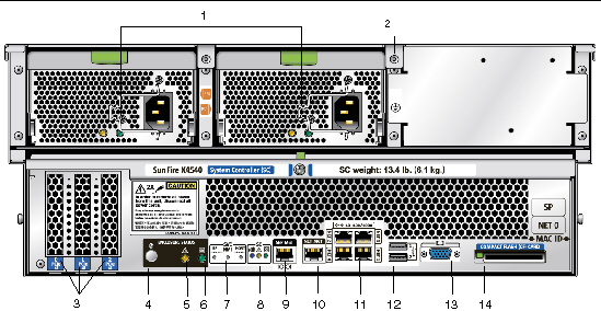
Rear Panel Features
FIGURE 14-3 shows all the features of the rear panel. TABLE 14-2 describes each rear panel feature.
FIGURE 14-3 Sun Fire X4540 Server Rear Panel
 [ D ]
[ D ]
TABLE 14-2 Rear Panel Features
|
#
|
Name
|
Description
|
|
1
|
AC power connectors
|
Verify that the PS LEDs are green. Each power supply has its own AC connector with a clip to secure its power cable.
|
|
2
|
Chassis ground
|
Connect grounding straps here.
|
|
3
|
0 PCI-e, 1 PCI-e, 2 PCI-e
|
Slots for three PCI-e cards.
|
|
4
|
Locate button/LED

|
White Operators can turn this LED On remotely to help then locate the server in a crowded server room. Press to turn off.
|
|
5
|
Fault LED

|
Amber - When on, service action required.
Steady - Power is On.
Off - Power is Off.
|
|
6
|
OK LED

|
Green - Service action allowed.
When On, service action is required.
Blink - Standby power is On but main power is Off.
|
|
7
|
SVC Service buttons
|
SP - Reset Service Processor.
NMI - Non-Maskable Interrupt dump. Sends an NMI to the CPU. Used for debugging only.
Host - Reset Host Bus Adapter.
Do not use these buttons unless instructed by Sun service personnel. To operate these buttons, insert a stylus or a straightened paper clip into the recess.
|
|
8
|
SC - System controller status LEDs
|
Blue - Ready to remove.

Amber - Fault, service action required.

Green - Operational, no action required.

|
|
9
|
SER MGT
|
Serial management port (serial connection to service processor).
|
|
10
|
NET MGT (S)
|
Net management and service processor port.
|
|
11
|
10/100/1000
|
GigabitEthernet ports connect server to Ethernet.
|
|
12
|
USB connectors
|
Connect USB devices.
|
|
13
|
Video connector
|
Connect video monitor.
|
|
14
|
Compact flash (CF) card
|
Insert compact flash card devices.
|
Internal Status Indicator LEDs
The Sun Fire X4540 server has internal status board LEDs for the CPU board, the CPU and DIMM slots on the CPU board. The system includes internal LEDs on the disk drives, the fan trays, and the PCI slots.
See the following figures and tables for information about the LEDs that you can view inside of the server.
Disk Drive and Fan Tray LEDs
FIGURE 14-4 shows the location of the disk drive and fan trays. FIGURE 14-5 shows a close-up view of the disk drive and fan trays and also shows the symbols that identify the LEDs.
FIGURE 14-4 Disk Drives and Fan Trays

FIGURE 14-5 Disk Drive and Fan Tray LEDs

CPU Board LEDs
The CPU board has three types of LEDs, DIMM fault, CPU fault, and battery fault.
The CPU LEDs are active only when the Remind button is depressed. CPU LEDs blink to indicate a failure, otherwise they stay Off.
| Note - The CPU and DIMM LEDs continue to indicate a failure until the system is powered on. The Battery LED continues to indicate a failure until the service processor is started.
|
Internal LEDs appear in FIGURE 14-6 and are listed in TABLE 14-3.
FIGURE 14-6 CPU Module LED and Button Locations

Figure Legend
|
1
|
DIMMs 0 2 1 3
|
|
2
|
CPU 1 (under heatsink)
|
|
3
|
CPU 0 (under heatsink)
|
|
4
|
DIMMs 3 1 2 0
|
|
5
|
DIMM fault LEDs
|
|
6
|
CPU 1 fault LED
|
|
7
|
Battery fault LED
|
|
8
|
CPU 1 fault LED
|
|
9
|
DIMM fault LED
|
TABLE 14-3 lists the internal LEDs.
TABLE 14-3 Internal LEDs
|
Name
|
Color
|
Function
|
- Disk Drives See FIGURE 14-5
|
|
Status
|
Green
|
Blinking, data is transfering, unit is OK.
|
|
Fault
|
Amber
|
Fault, service action is required.
|
|
Ready to Remove
|
Blue
|
Unit is ready to remove. Service action allowed.
|
- Fan Trays See FIGURE 14-5
|
|
Status
|
Green
|
Unit is OK.
|
|
Fault
|
Amber
|
Fault, service action is required.
|
- CPU See FIGURE 14-6. LEDs are active only when the Remind button is pressed.
|
|
DIMM Failure
|
Amber
|
Blinks to indicate that the system has found a fault with the DIMM. Restart system to clear fault.
|
|
CPU Failure
|
Amber
|
Blinks to indicate that the system has found a fault with a CPU. Restart system to clear fault.
|
|
Battery Failure
|
Amber
|
Blinks to indicate that the system has found a fault with the battery. Start service processor to clear fault.
|
| Sun Fire X4500/X4540 Servers Diagnostics Guide
|
819-4363-12
|
   
|
Copyright © 2009 Sun Microsystems, Inc. All rights reserved.